Tekram Technology DC-390U User manual

DC-390 Series User’s Manual 11
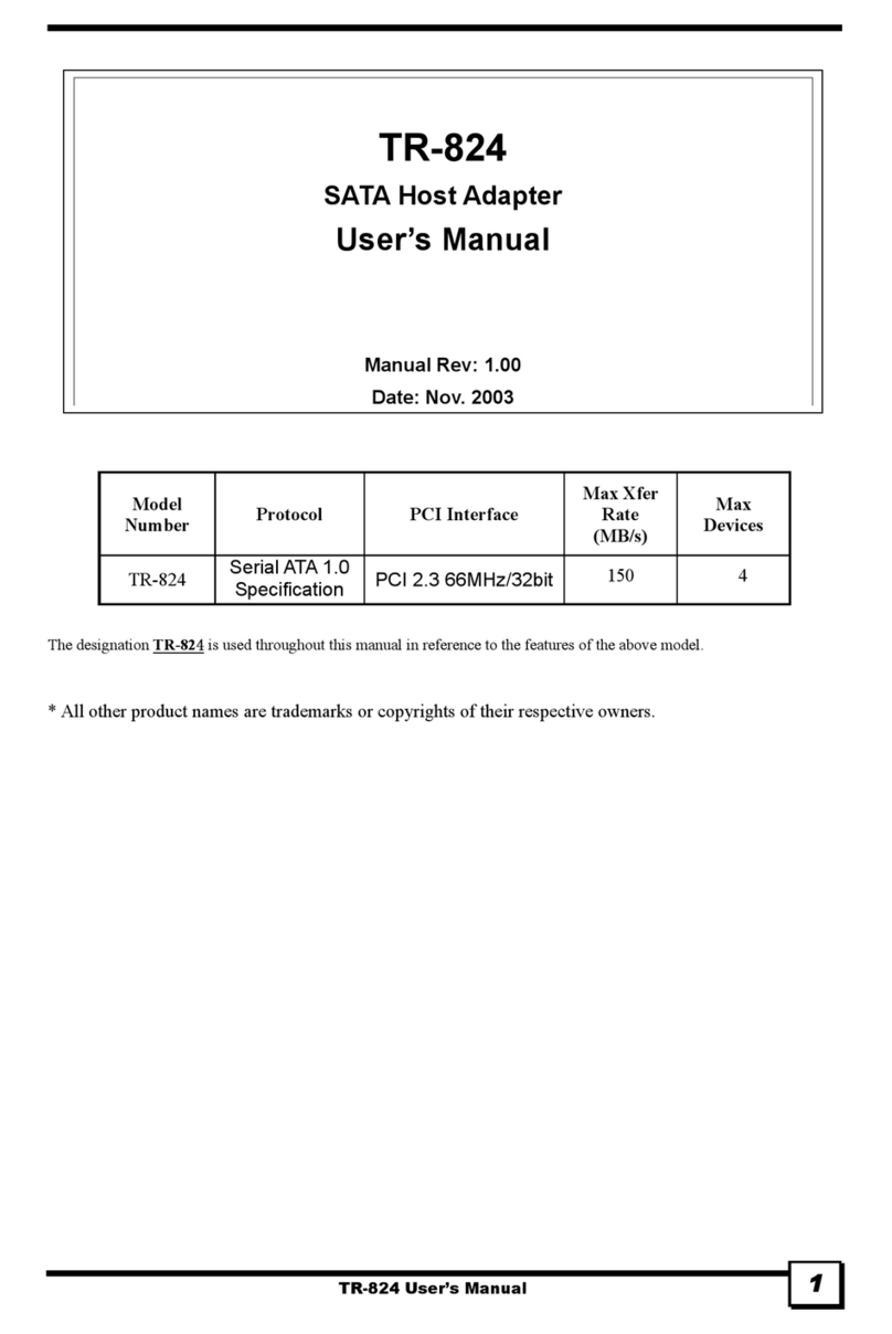
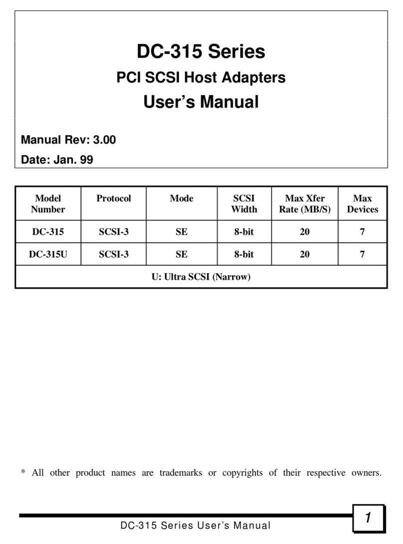
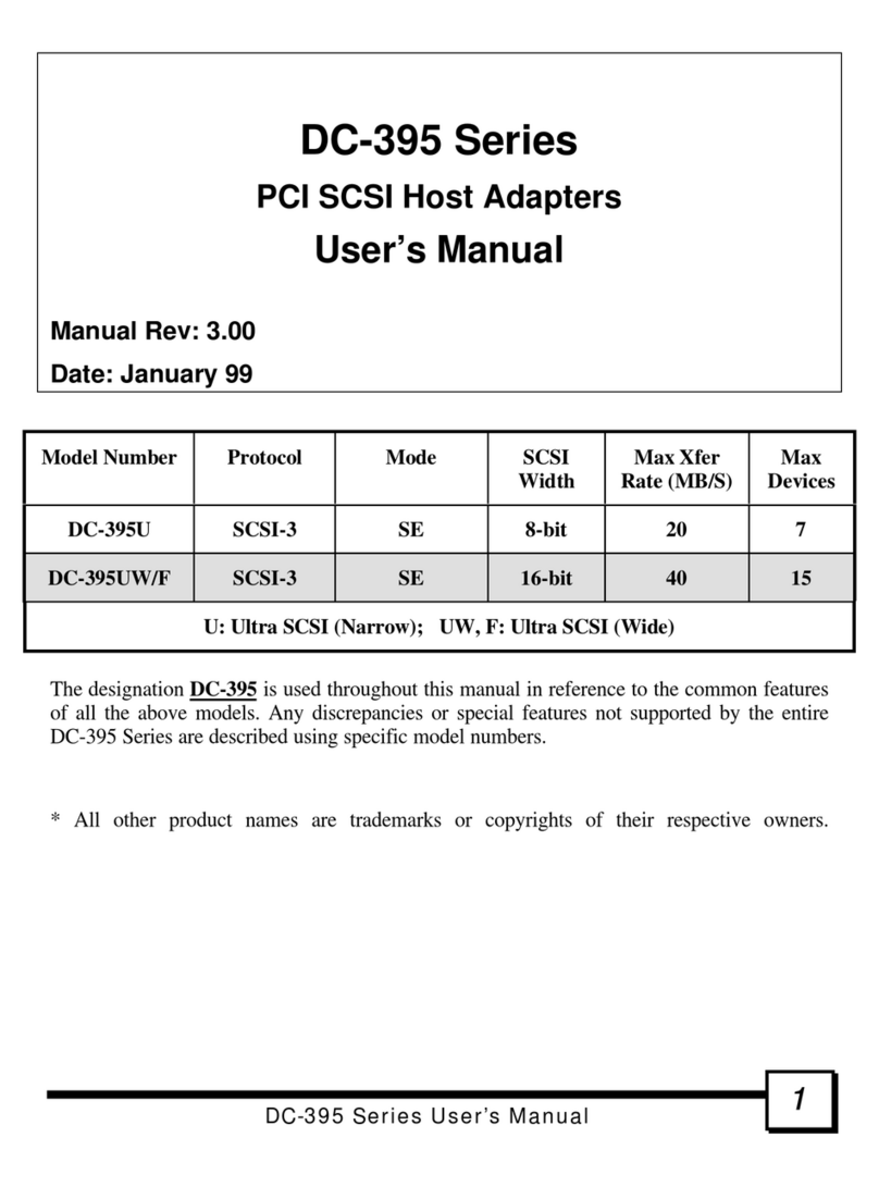
DC-390 Series
PCI SCSI Host Adapters
User’s Manual
Manual Rev: 6.00
Date: April 99
Model
Number Protocol Mode SCSI
Width Max Xfer
Rate (MB/S) Max
Devices
DC-390 SCSI-2 SE 8-bit 10 7
DC-390U SCSI-3 SE 8-bit 20 7
DC-390F SCSI-3 SE 16-bit 40 15
DC-390U2B Wide Ultra2 SE or LVD 16-bit 80 15
DC-390U2W Wide Ultra2 SE and LVD 16-bit 80 15
U: Ultra SCSI (Narrow); F: Ultra SCSI (Wide); U2: Wide Ultra2 SCSI
The designation DC-390 is used throughout this manual in reference to the common features
of all the above models. Any discrepancies or special features not supported by the entire
DC-390 Series are described using specific model numbers.
* All other product names are trademarks or copyrights of their respective owners.

DC-390 Series User’s Manual
22
FCC Compliance Statement
This equipment has been tested and found to comply with limits for a Class B digital device,
pursuant to Part 15 of the FCC rules. These limits are designed to provide reasonable
protection against harmful interference in residential installations. This equipment generates,
uses, and can radiate radio frequency energy, and if not installed and used in accordance with
the instructions, may cause harmful interface to radio communications. However, there is no
guarantee that interference will not occur in a particular installation. If this equipment does
cause interference to radio or television equipment reception, which can be determined by
turning the equipment off and on, the user is encouraged to try to correct the interference by
one or more of the following measures:
•Reorient or relocate the receiving antenna
•Move the equipment away from the receiver
•Plug the equipment into an outlet on a circuit different from that to which the
receiver is connected
•Consult the dealer or an experienced radio/television technician for additional
suggestions
Only equipment certified to comply with Class B should be attached to this equipment, and
must have shielded interface cables.
The FCC requires the user to be notified that any change or modifications to the equipment
by the user not expressly approved by the grantee or manufacturer could void the user's
authority to operate such equipment.
Each DC-390 is equipped with an FCC compliance label which shows only the FCC
Identification number: FCC ID: KHADC-390.
This device complies with Part 15 of the FCC rule. Operation is subjected to the following
two conditions: 1) This device may not cause harmful interference and 2) This device must
accept any interference received, including interference that may cause undesired operation.
DC-390 Series
Tested to Comply
with FCC Standards
For Home or Office Use

DC-390 Series User’s Manual 33
Award BIOS with built-in NCR SCSI BIOS & DC-390 Controllers
– Possible Compatibility Problem:
Why and when the problem occurs
The built-in SCSI BIOS feature incorporated into some mainboards with Award BIOS is
meant to control NCR/Symbios Logic-based SCSI adapters that have no BIOS of their own.
Since the DC-390 controllers use Symbios SCSI chips, some mainboards with built-in NCR
or Symbios Logic SCSI BIOS may detect these cards and load their own BIOS to control
them. This happens because Award BIOS checks only the Vendor ID (NCR/Symbios) and
Class Code (SCSI device) to determine if a suitable adapter exists to enable the built-in SCSI
BIOS. This situation can arise with mainboards equipped with either of the following:
•Earlier versions of Award BIOS with NCR SCSI BIOS support
•NCR (Symbios) V3.0 SCSI BIOS built-in (supports only 53C810/20 chips)
How to verify if you have this problem
This problem can be verified by observing which BIOS banner is displayed upon bootup. If
an NCR or Symbios Logic BIOS banner is displayed, the problem exists. If only the Tekram
BIOS banner is displayed, there should be no problem. If the NCR or Symbios Logic banner
is observed, take out the DC-390 and make sure that the banner goes away. This will verify
that the built-in SCSI BIOS is being loaded to control the Tekram card. If this is the case, try
the following solutions:
Solutions
1. See if there is a way to set the built-in or “on-board” SCSI BIOS to “Disabled” instead
of “Enabled” or “Auto” in the mainboard’s BIOS Setup. This is the easiest solution if
such an option is available. If not, see if a BIOS upgrade for the mainboard is available
with this option.
2. Remove the built-in SCSI BIOS from the mainboard’s Award BIOS using PROG.ZIP –
available at http://www.tekram.com or ftp://ftp.tekram.com. This file contains the
following files:
PROG.BAT Batch file used to remove built-in NCR SCSI BIOS or
restore original mainboard BIOS. This is written by
Tekram.
AWDFLASH.EXE Utility to retrieve or program mainboard BIOS.
CBROM.EXE Utility to remove built-in NCR SCSI BIOS from mainboard
BIOS’s binary file.

DC-390 Series User’s Manual
44
TABLE OF CONTENTS
1. INTRODUCTION.................................................................................7
2. HARDWARE SETUP..........................................................................8
2.1 Board Layout....................................................................................................9
2.2 Setting the Jumpers.........................................................................................12
2.3 Setting the SCSI IDs.......................................................................................12
2.4 Checking the Terminators on the SCSI Bus.....................................................13
2.5 Cable Connection ...........................................................................................14
2.6 Coexisting with Symbios 53C810/53C860-based Card ....................................15
3. CONFIGURING YOUR SCSI CARD..................................................16
3.1 Setting the System BIOS................................................................................. 16
3.2 Running the PCU (PCI Configuration Utility).................................................. 18
3.2.1 Show Adapter Information ..................................................................19
3.2.2 Set Adapter Options............................................................................19
3.2.3 Set Devices Options............................................................................24
3.2.4 Show SCSI Devices............................................................................. 27
3.2.5 Low Level Format Utility....................................................................28
3.2.6 Verify Disk Utility...............................................................................28
4. DOS ASPI DRIVERS & UTILITIES ...................................................29
4.1 Easy DOS Driver Installation Software (INSTALL.EXE) ................................ 30
4.2 Installing the ASPI Driver...............................................................................33
4.3 Installing the TRMDISK.SYS Driver..............................................................33
4.4 Disk Partition Utility....................................................................................... 35
4.5 Installing the CD-ROM Driver........................................................................ 36
4.6 Installing Tape Streamer (DAT)...................................................................... 37
5. NETWARE DRIVERS .......................................................................38
5.1 ASPI Drivers for NetWare.............................................................................. 38
5.1.1 NetWare 5.0 ....................................................................................... 38
5.1.2 NetWare 4.xx......................................................................................39
5.1.3 NetWare 3.12/SFT-III .........................................................................41

DC-390 Series User’s Manual 55
5.2 Driver Options................................................................................................43
5.3 Server-based Backup/Restore Support............................................................. 44
5.4 Removable Media Support..............................................................................44
5.5 Duplexing ......................................................................................................45
6. OS/2 DRIVERS.................................................................................46
6.1 New OS/2 Installation..................................................................................... 46
6.2 Adding the Driver to an Existing OS/2 System ................................................47
6.3 Un-installing the Driver..................................................................................48
6.4 Command-Line Switches for TMSCSIM.ADD................................................ 49
7. WINDOWS NT DRIVERS..................................................................50
7.1 New Windows NT Installation........................................................................ 50
7.2 Adding the Driver to an Existing NT System................................................... 52
7.2.1 For NT Versions 3.x and 3.5x.............................................................. 52
7.2.2 For NT Versions 4.x............................................................................52
7.3 Removing the SCSI Host Adapter from the System .........................................53
7.3.1 For NT Versions 3.x and 3.5x.............................................................. 53
7.3.2 For NT Versions 4.x............................................................................53
8. WINDOWS 3.X DRIVERS.................................................................54
8.1 Driver Installation........................................................................................... 54
8.2 Driver Un-installation.....................................................................................54
9. WINDOWS 95/98 DRIVERS..............................................................55
9.1 Installing the Windows 95 Driver....................................................................55
9.2 Installing the Windows 95 OSR2 Driver.......................................................... 56
9.3 Installing the Windows 98 Driver....................................................................57
9.4 Adding the Driver to an Existing 95/98 System ...............................................59
9.4.1 For an Existing Windows 95 System....................................................59
9.4.2 For an Existing Windows 95 OSR2 System ..........................................59
9.4.3 For an Existing Windows 98 System....................................................60
10. SCO UNIX DRIVERS........................................................................61
10.1 Preparing a Driver Diskette............................................................................. 61
10.2 New SCO UNIX Installation...........................................................................62

DC-390 Series User’s Manual
66
10.3 Adding the Driver to an Existing SCO UNIX System ......................................63
APPENDIX...............................................................................................64
A. Specifications.................................................................................................64
B. Product Support Form..................................................................................... 65
C. General Troubleshooting Tips.........................................................................66
D. Flash BIOS Programming Utility ....................................................................71

DC-390 Series User’s Manual 77
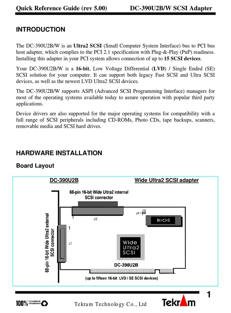
1. INTRODUCTION
The DC-390 series is a SCSI (Small Computer System Interface) bus to PCI bus host adapter,
which complies to the PCI 2.1 specification with Plug-&-Play (PnP) readiness. By using the
Disconnect/Reconnect technique, performance degradation during multitasking operations is
prevented. Other enhanced SCSI-2 features such as scatter-gather and command-tag queuing
are supported. The DC-390U2B/W is a 16-bit, Low Voltage Differential (LVD) / Single
Ended (SE) Ultra2 SCSI solution. DC-390U2W can support both the legacy Fast SCSI and
Ultra SCSI as well as the newest LVD Ultra2 SCSI without down-grading the Ultra2
performance.
The DC-390 series supports ASPI (Advanced SCSI Programming Interface) managers for the
following operating systems to assure operation with popular third party applications:
•MS-DOS •Windows 3.x/95/98/NT •OS/2 2.0/WARP 3.0/4.0 •NetWare 3.x/4.x
Device drivers are also supported for the following major operating systems for
compatibility with a full range of SCSI peripherals including CD-ROMs, Photo CDs, tape
backups, scanners, removable media and SCSI hard drives:
•MS-DOS •Windows 3.x (& WFWG 3.x)
•Windows NT 3.x/4.0 •Windows 95/98
•OS/2 2.0/WARP 3.0/4.0 •NetWare 3.x/4.x
•SCO Unix 3.2v4.x & OpenServer 5.0 •UnixWare 1.1 (SVR4.2 version1)
* UnixWare, Slackware/RedHat Linux, and FreeBSD drivers can be accessed via
www.tekram.com or ftp.tekram.com/scsi.
Most SCSI Adapters require device drivers to support more than 2 hard drives under DOS.
The DC-390 series, however, provides special support to handle up to eight devices,
including fixed disks and removable media under MS-DOS 5.0/6.x, without the need for
device drivers (More than 2 drives support).
The on-board menu-driven setup and jumperless design of the DC-390 series allow you to
configure the host adapter, SCSI devices, and BIOS-related parameters without opening your
computer. The DC-390 series also provides a utility program that supports low-level
formatting. And with the help of the DOS driver installation software (INSTALL.EXE), the
drivers are easily installed and the CONFIG.SYS and AUTOEXEC.BAT files are
automatically updated.
The fully intelligent solution provided by the DC-390 PCI to SCSI Host Kit is ideal for
multitasking environments such as OS/2, NetWare, Unix, Microsoft Windows 95 and
Windows NT, as well as next generation operating systems such as Microsoft Windows 98.
DC-390 Series User’s Manual
88
2. HARDWARE SETUP
Static Precautions
Static electricity can be a serious danger to the electronic components on this board. To avoid
damage caused by electrostatic discharge, observe the following precautions:
üDon’t remove the board from its anti-static packaging until you are ready to install it into
a computer case. Also, handle add-in cards and modules by the edges or mounting
bracket.
üBefore you handle the board in any way, touch a grounded, anti-static surface, such as an
unpainted portion of the system chassis, for a few seconds to discharge any built-up static
electricity.
Before plugging the DC-390 series adapter into your system, make sure all jumpers on the
card are correctly set according to the instructions outlined in section 2.2. Also take care that
the SCSI ID number (0-6 for DC-390/390U; 0-15 for DC-390F/390U2B/390U2W) of each
SCSI device is set properly for the host adapter (Section 2.3).
The maximum devices that can be installed on each model are show below:
Model # Max. Devices Number
DC-390 7
DC-390U 7
DC-390F 15 *
DC-390U2B 15
DC-390U2W 15 *
•For DC-390F, up to fifteen 16-bit and/or 8-bit SCSI single ended (SE) devices can be
connected. Up to seven of these can be 8-bit. And only two of the three SCSI connectors,
either Internal or External, can be used to connect SCSI devices at any given time.
•For DC-390U2B, mixing Fast/Ultra devices with Ultra2 devices brings the entire SCSI
bus to Ultra SCSI speed and cable requirements.
•For DC-390U2W, it is recommended that you keep your Ultra2 devices separate from
your non Ultra2 devices. Mixing Ultra2 devices with non Ultra2 devices will bring the
Ultra2 devices to Ultra SCSI performance level.
Correct termination and cable connections are also necessary for SCSI adapters to function
properly (Section 2.4 and 2.5).

2. HARDWARE SETUP
DC-390 Series User’s Manual 99
2.1 Board Layout
The following figures illustrate the jumper and connector locations for the DC-390 Series
PCI SCSI Host Adapters:
DC-390 Fast SCSI-2 adapter
DC-390U Ultra SCSI-3 adapter

2. HARDWARE SETUP
DC-390 Series User’s Manual
1010
DC-390F Ultra Wide SCSI-3 adapter
DC-390U2B Wide Ultra2 SCSI adapter

2. HARDWARE SETUP
DC-390 Series User’s Manual 1111
DC-390U2W Wide Ultra2 SCSI adapter
For DC-390U2B/W:
When any SE device is connected on the Ultra2 connector(s) (J1 and/or J2), all the LVD
devices on the connector(s) will be down-graded to SE performance.
Therefore, it is recommended that non-Ultra2 devices are not to be used on DC-390U2B. For
DC-390U2W, non-Ultra2 devices should be kept on connectors CN1 and CN2.
There are four connectors in DC-390U2W which can be separated into two independent SCSI
buses using 53C141 SCSI Bus Expander (http://www.lsilogic.com/products/sym53c141.htm).
One is Ultra 2 connector (s) (J1 and J2) and the other is single-ended connector(s) (CN1 and
CN2). It is not an expander and the total devices are only 15 for this card. The Max. Cable
Length is calculated by each other. The terminator is set as two SCSI cards.

2. HARDWARE SETUP
DC-390 Series User’s Manual
1212
2.2 Setting the Jumpers
DC-390: JP1 (LED); JP2 (ROM)
DC-390U/390F/390U2B/390U2W: JP1 (LED)
SCSI Device Activity LED Indicator (JP1)
JP1 is used to indicate activity of the SCSI devices controlled by the DC-390 series adapter,
and should be connected to the cable leading to the Hard Drive LED on the front panel of
your computer case.
ROM BIOS jumper (JP2/DC-390 only)
You can install a maximum of 4 DC-390s in the same system. However, early mainboard
BIOS cannot initialize adapter PCI ROM when multiple DC-390s are installed (Newer
mainboard BIOS should not have this problem). When this occurs, set JP2 to Enabled for the
first adapter, and Disabled for all additional DC-390s. The BIOS of the first DC-390 will
control all others installed.
2.3 Setting the SCSI IDs
Each SCSI device attached to the SCSI card, as well as the card itself, must be assigned a
unique SCSI ID number. SCSI ID 7 is preset to the SCSI card, giving it the highest priority
on the SCSI bus.
The SCSI IDs of your peripheral devices are usually set with jumpers or with a switch on the
peripheral. Refer to the peripheral manufacturer’s manual to determine the ID of each device
and how to change it.
Any SCSI device with SCAM (SCSI Configured AutoMatically) can assign its own SCSI ID
dynamically and resolves SCSI ID conflicts automatically. You do not need to manually
assign SCSI IDs to theses peripherals. See page 23 to enable SCAM support.

2. HARDWARE SETUP
DC-390 Series User’s Manual 1313
2.4 Checking the Terminators on the SCSI Bus
In order to stabilize the SCSI bus, only two sets of terminators can be installed - one at each
end of the SCSI bus. The DC-390 series is equipped with Active Terminators that
automatically switch from Enabled to Disabled or vice versa by scanning the devices
connected on the SCSI bus. So, manual termination adjustment is not required. The following
explains the terminator configuration of other devices on the SCSI bus:
1. When only internal devices are connected to the DC-390 series adapter: Leave the
terminator mounted on the last device only, with the SCSI card being the first SCSI
device. Remove terminators on all other devices connected in between.
2. When only external devices are connected to the DC-390 series adapter: Leave the
terminators mounted on the last device only. Since external SCSI devices are daisy
chained, this would be the device without another SCSI cable plugged into it. Remove
terminators on all other devices connected in between.
3. When both internal and external devices are connected to the DC-390 series adapter:
Leave only the terminators mounted on the last internal device and the last external
device. As in the above case, remove the terminators from all other devices connected in
between.
Note1: For DC-390F only: When both Narrow (8-bit) and Wide (16-bit) devices are
connected to the Wide SCSI connector (either Internal or External), arrange the
devices so that a Wide device with termination enabled is at the end of the bus. A
Narrow device at the end of the bus can have termination problems in this case,
since the Wide bus is 16-bit and the terminator on the Narrow device is only
effective for the lower 8-bit (not the whole 16-bit).
Note2:DC-390U2B/W only: Since the termination of internal Ultra2 devices are set to
disabled at the factory and cannot be changed, special Ultra2 internal SCSI ribbon
cables with a terminator installed at the end are specified for the operation with
Ultra2 SCSI devices.
Note3: There are two types of termination available on SCSI devices, active and passive.
Active termination is strongly recommended to ensure system integrity, particularly
when devices with high transfer rates are being used. A SCSI CD-ROM drive
usually comes with a passive terminator. For proper termination, it is recommended
that you keep this terminator disabled, i.e. avoid connect the CD-ROM drive at the
end of the SCSI bus

2. HARDWARE SETUP
DC-390 Series User’s Manual
1414
2.5 Cable Connection
Model # External Internal
DC-390 CN1: 50-pin; 8-bit (Female) CN2: 50-pin; 8-bit (Male)
DC-390U CN1: 50-pin; 8-bit (Female) CN2: 50-pin; 8-bit (Male)
DC-390F*CN1: 68-pin; 16-bit
(wide, Female) CN2: 68-pin; 16-bit (wide, Female)
CN3: 50-pin; 8-bit (Male)
DC-390U2B J1: 68-pin; 16-bit
(wide Ultra2, Female) J2: 68-pin; 16-bit
(wide Ultra2, Female)
DC-390U2W J2: 68-pin; 16-bit
(wide Ultra2, Female) CN1: 50-pin; 8-bit (Male)
CN2: 68-pin; 16-bit (wide, Female)
J1: 68-pin; 16-bit (wide Ultra2,
Female)
* Only two of the three connectors can be used to connect SCSI devices at the same
time.
External SCSI connector: This high density D-type SCSI connector is for connecting
external SCSI devices.
Internal SCSI connector: The internal flat cable should connect to the internal SCSI
connector with its colored stripe, normally red, aligned with Pin 1 of the connector.
Maximum length of the SCSI bus is determined by the number of devices and the data
transfer rate. The following table summarizes the maximum allowable cable lengths for the
DC-390 series:
Model # SCSI Type Data Xfer
Rate Max. # of
Devices Max. Cable Length
DC-390 SCSI-2 10 MB/Sec 83 meters (9.8 feet)
DC-390U/F Ultra SCSI 20/40 MB/Sec 43meters (9.8 feet)
DC-390U/F Ultra SCSI 20/40 MB/Sec 81.5 meters (4.9 feet)
DC-
390U2B/U2W Wide Ultra2
SCSI 80 MB/Sec 16 12.5 meters (41 feet)
•If there are internal devices connected, the internal cable length must be included in
the measurement of SCSI bus length.
•For DC-390U2B, mixing Fast/Ultra devices with Ultra2 devices brings the entire SCSI
bus to Ultra SCSI speed and cable requirements.
•For DC-390U2W, it is recommended that you keep your Ultra2 devices on connectors J1
and J2, non Ultra2 devices on CN1 and CN2. Mixing Ultra2 devices with non Ultra2
devices will bring the Ultra2 devices to Ultra SCSI performance level.

2. HARDWARE SETUP
DC-390 Series User’s Manual 1515
2.6 Coexisting with Symbios 53C810/53C860-based Card
[1] When you use DC-310/U or other Symbios 53C810 cards having EEPROM built on
board with DC-390U/F/U2B/U2W, please only use tekram driver.
[2] If you use DC-310/U only or with other none-Symbios chip card , you have to use
Symbios driver, not Tekram driver. (The latest Symbios driver can get from LSI’S web
site http://www.lsi.com.)
[3] Other cards with 53C810 chip (without EEPROM) can not co-exist with
DC-390U/F/U2B/U2W.

DC-390 Series User’s Manual 1616
3. CONFIGURING YOUR SCSI CARD
3.1 Setting the System BIOS
After the DC-390 is inserted in an available PCI-BUS slot and the jumpers and cables are
properly set, first turn on the power to your external SCSI devices and then power on the
system. When installing a SCSI drive as drive C: (or D:), set the CMOS HDD drive type
according to the IDE drive installed. The CMOS HDD is NOT related to SCSI HDD.
Note:With most mainboards, IDE (Intelligent Drive Electronics)/ST506 and ESDI
(Enhanced Small Device Interface) drives always take precedence over SCSI drives.
That means that if one IDE/ST506/ESDI drive has already been installed, you cannot
install the SCSI drive as drive C:. If two IDE/ST506/ESDI drives already exist, no
SCSI drives can be installed as C: or D:. However, if your mainboard BIOS has
multiple boot options, such as “boot from SCSI device”, this will allow the system to
boot from any bootable SCSI device connected to the DC-390 series controller.
Since the mainboard BIOS will automatically shadow the PCI adapter’s BIOS, there is no
need to set the shadow option between C800 and DFFF. This option is for ISA adapter ROM
only. The I/O Base Address and IRQ ROM shadow addresses are also assigned by the
mainboard BIOS automatically. You do not need to worry about it. Just Plug & Play and
enjoy it.
Right after exiting the system BIOS CMOS setup, the following message will pop up and
prompt you to enter the PCI Configuration Utility to configure the card:
TEKRAM DC-390 PCI-SCSI Controller
BIOS v3.00 Date: 1998-4-20
Installed at IOPORT = 6800h, IRQ =10 - Level triggered
BIOS ROM mapped at C800h
<< Press F2 or F6 to enter configuration Menu >>
ID-LUN:6-0 MICROP 2217-15MZ1001905HQ30 Fixed disk 1678MB ==> C: (80h)
C/H/S=214/253/63, Xfer Rate=10.0MB/Sec, Sync Offset=15Bytes
ID-LUN:3-0 SONY CD-R CDU924S 1.1d CD-ROM
Xfer Rate=4.0MB/Sec, Sync Offset=15Bytes
SCSI BIOS installed !

3. CONFIGURING YOUR SCSI CARD
DC-390 Series User’s Manual 1717
After powering up the system, the DC-390U/F/U2B/U2W BIOS will show a message with
two screen indicating its BIOS version with a date code and information about the IOPORT
address, IRQ number and address that the ROM BIOS is mapped at
TEKRAM DC-310 PCI-SCSI Controller
BIOS v3.04 Date: 1999-2-11
Installed at IOPORT = E400h, IRQ =9 - Level triggered
BIOS ROM mapped at C800h
<< Press F2 or F6 to enter configuration Menu >>
TEKRAM DC-390U PCI-SCSI Controller
BIOS v3.04 Date: 1999-2-11
Installed at IOPORT = E800h, IRQ =10 - Level triggered
BIOS ROM mapped at C800h
<< Press F2 or F6 to enter configuration Menu >>
. Upon pressing the <F2> or <F6> key, the following screen will pop up:
Select An Adapter To Setup
DC-310 >>>>
DC-390 >>>>
BUS00
BUS00
Dev0A
Dev0B
Fun0 : IO = E400h
Fun0 : IO = E800h
IRQ = 09
IRQ = 05
Note: It is normal when it appears “No BIOS Disk Found! SCSI BIOS Not Installed” or “NO
SCSI boot device found => BIOS not installed !” during system boot. It represents that there
was no bootable SCSI device such as SCSI HDD found after SCSI BIOS detected peripheral
devices. Thus, above messages are shown and they will not affect system operation.

3. CONFIGURING YOUR SCSI CARD
DC-390 Series User’s Manual
1818
3.2 Running the PCU (PCI Configuration Utility)
Since the DC-390 series is PCI compliant with Plug-&-Play (PnP) readiness, the system
should allocate the proper Interrupt Level, Adapter BIOS Address and other settings
automatically. Still, entering the PCU allows you to view more information and set additional
options for both the DC-390 series adapter and the SCSI Devices. Utilities for verifying bad
blocks and low level formatting are also included. Another alternative is to run the provided
DOS utility program UTIL.EXE, which performs the same functions as the PCU does.
Note: UTIL.EXE may be the only way to change options in the configuration of DC-390
series adapter in the event that either a) The DC-390’s BIOS is disabled OR b) The
option “F2 or F6 Function During Bootup” is disabled. It also allows you to modify
your settings without rebooting to enter the PCU. When running UTIL.EXE, it’s best
to boot clean from a DOS floppy disk.
After powering up the system, the DC-390's BIOS will show a message indicating its BIOS
version with a date code and information about the IOPORT address, IRQ number and
address that the ROM BIOS is mapped at. Upon pressing the <F2> or <F6> key, the
following screen will pop up:
Select An Adapter To Setup
DC-390 >>>> BUS#00 DEV#0C IOPORT = 9600h IRQ = 11
If two or more adapters are installed, choose the desired adapter to proceed with the
configuration. After pressing <Enter>, the SCSI bus will be reset and the SCSI IDs for all
devices installed on the SCSI bus will be scanned. A selection table for further operations
will be shown as follows:
Function Selection
Show Adapter Information
Set Adapter Options
Set Devices Options
Show SCSI Devices
Low Level Format
Verify Disk
The sections that follow contain detailed descriptions of the above options.

3. CONFIGURING YOUR SCSI CARD
DC-390 Series User’s Manual 1919
3.2.1 Show Adapter Information
This screen displays detailed information about the SCSI chip, ROM BIOS address, I/O port
address, IRQ, PCI interrupt line, etc. The information about the SCSI Chip, IRQ Trigger
Type and Data Xfer Type is provided by the DC-390 series adapter itself. The rest of the
information in this table is provided by the mainboard's BIOS, which should support the PCI
PnP specification. This information cannot be modified.
Adapter Information
SCSI Chip …………………... AM53C974A
Bus Type ……………………. PCI Bus
Bus# ………………………… 00h
Device# ……………………... 0Ch
Function# ……………………. 00h
BIOS ROM mapped at ……... CC00h
IO Address ………………….. 96000h
PCI Interrupt Line ………….. INTA#
IRQ# ………………………... 11
IRQ Trigger Type …………... Level triggered
Data Xfer Type ……………... PCI Bus Master
3.2.2 Set Adapter Options
Set Adapter Options
Adapter SCSI ID ………………………. SCSI ID 7 -- Default
Boot Device ID ………………………… SCSI ID 0 -- Default
Boot Device LUN ……………………... LUN 0 -- Default
Boot From CD-ROM ………………….. Disabled -- Default
INT13 Extension ……………………… Enabled -- Default
Greater Than 1G Support ……………... Enabled -- Default
More Than 2 Drives Support ………… Enabled -- Default
Removable Media as BIOS Device …. Boot only -- Default
Immediate Return on SEEK Command… Disabled -- Default
Scan All LUN For Devices…………… Disabled -- Default
Active Negation ……………………….. Enabled -- Default
Power on RESET SCSI Bus ………….. Enabled -- Default
Delay Before BIOS scans device ……… 3 sec -- Default
Max Number of Tagged Commands … 32 -- Default
SCAM Support ….…………………….. Enabled -- Default
F2 or F6 Function During Bootup ……. Enabled -- Default
Pressing <F8> will reset all the settings to their default values.

3. CONFIGURING YOUR SCSI CARD
DC-390 Series User’s Manual
2020
Adapter SCSI ID: 0-7. The default ID for the DC-390 series adapter is 7. It is recommended
not to change this default value of 7, as it gives the adapter the highest priority on the SCSI
bus. However, if you have two adapters on the same SCSI bus, you should give one of them a
currently unassigned ID.
Note:For DC-390F/390U2B/U2W, sixteen SCSI IDs 0-15 are available. If there is any 8-bit
device connected on the SCSI bus, avoid setting the adapter SCSI ID to the number 8
or larger otherwise you may run into difficulties.
Boot Device ID: SCSI ID 0 (default) – 7 (DC-390/DC-390U) or 15 (DC-390F/390U2B/
390U2W). This option allows you to boot from any bootable devices connected. To ensure
proper operation, see the following notes:
•If a bootable IDE drive is
installed in the system: The IDE drive will boot by default before any SCSI
devices. This is a function of the mainboard’s BIOS. To
boot from a SCSI device in this case, a setting in the
mainboard BIOS such as “Boot From SCSI” must be
available.
•Booting from a removable
SCSI device:The above applies. Also, the setting Removable media as
BIOS device (see page 22) should be set to “Boot drive
only” *
•Booting from a SCSI CD-
ROM:The setting Boot From CD-ROM (see below) must be
“Enabled” (for CD-Changer, Boot Device LUN may need
additional configuration). This setting takes precedence
over the boot device setting in the mainboard’s BIOS.
(*) Since removable media with 2048 Byte/sector is not supported by the system BIOS,
this type of media won’t be accepted as a Bootable device by the system.
Boot Device LUN: LUN 0 (default) - 7. If the SCSI device you wish to boot from has a LUN
number other than 0, this option must be set for the specific LUN number in addition to
setting the Boot Device ID for the SCSI ID number.
Boot From CD-ROM: Disabled/Enabled. When enabled, the option will be given to boot
from CD-ROMs detected by the controller as bootable. This setting takes precedence over
any settings in the mainboard BIOS such as “boot from IDE”. The Boot Device ID and Boot
Device LUN (if LUN is not 0) settings can be adjusted to ensure proper operation. If these
options are left on the default, the bootable CD-ROM with the lowest SCSI ID / LUN number
will boot if there is more than one bootable CD-ROM.
Note: Don’t confuse these settings with the “Boot From CD-ROM” option in the
mainboard’s BIOS setup, which is relevant only to ATAPI CD-ROMs.
This manual suits for next models
4
Table of contents
Other Tekram Technology Host Adapter manuals
Popular Host Adapter manuals by other brands

ATTO Technology
ATTO Technology ExpressSAS R608 RAID Installation and operation manual

ATTO Technology
ATTO Technology Celerity FC-41EL Installation and operation manual

HighPoint
HighPoint RocketRAID 231x user guide

HighPoint
HighPoint RocketRAID 4520 Quick installation guide

Tripp Lite
Tripp Lite U250-002-R owner's manual

IBM
IBM 59P5712 Installation and user guide