TEKTELIC Communications T0006086 User manual

USER GUIDE
Document Type:
User Guide
Document Number:
T0006377_UG
Document Version:
0.5
Product Name:
Meeting Room Display Tablet
Product Codes &
Revisions:
T0006086 –Battery Powered Digital Signage, NA
T0006093 –Externally Powered Digital Signage, NA
Issue Date:
Mar 2, 2020
Meeting Room Display Tablet User Guide T0006377_UG Version 0.5
TEKTELIC Communications Inc. Confidential Page 2 of 28
Revision History
Version
Date
Editor
Comments
0.1
July 17, 2019
Emma Tholl
Initial Draft.
0.2
November 7,
2019
C Karperien
General updates and template updates
0.3
November 25,
2019
A Narayanan
Updated to include Tablet specific instructions.
0.4
December 5,
2019
C Karperien
General Updates and addition of Firmware Upgrade
Feature
0.5
March 2, 2015
A. Narayanan
Updated Tcodes in Table 1 and Temperature
specification in Table 2

Meeting Room Display Tablet User Guide T0006377_UG Version 0.5
TEKTELIC Communications Inc. Confidential Page 3 of 28
Table of Contents
List of Tables ................................................................................................................................... 5
List of Figures .................................................................................................................................. 6
1Product Description................................................................................................................. 7
1.1 Overview .......................................................................................................................... 7
1.2 Specifications.................................................................................................................... 8
1.3 Physical Interfaces.......................................................................................................... 10
2Commissioning ...................................................................................................................... 12
2.1 Power Up/Down Procedure ........................................................................................... 12
3Installation ............................................................................................................................. 13
3.1 Included Product and Installation Material ................................................................... 13
3.2 Safety Precautions.......................................................................................................... 13
3.3 Unpacking and Inspection.............................................................................................. 13
3.4 Equipment Required for Installation.............................................................................. 14
3.5 Meeting Room Display Tablet mounting ....................................................................... 14
3.6 Battery Replacement...................................................................................................... 16
4Graphical User Interface........................................................................................................ 17
4.1 Available ......................................................................................................................... 17
4.2 Occupied......................................................................................................................... 19
5Operation, Alarms, and Management................................................................................... 21
5.1 Configuration.................................................................................................................. 21
5.2 Default Configuration..................................................................................................... 21
5.3 LED Behaviour ................................................................................................................ 21
6Firmware Upgrade Feature ................................................................................................... 22
6.1 Overview ........................................................................................................................ 22
6.2 Prerequisites................................................................................................................... 22
6.3 Setup .............................................................................................................................. 22
6.4 Firmware Upgrade ......................................................................................................... 24
7Compliance Statements......................................................................................................... 26


Meeting Room Display Tablet User Guide T0006377_UG Version 0.5
TEKTELIC Communications Inc. Confidential Page 5 of 28
List of Tables
Table 1: Meeting Room Display Tablet Models ............................................................................. 7
Table 2: Meeting Room Display Tablet Specifications................................................................... 9

Meeting Room Display Tablet User Guide T0006377_UG Version 0.5
TEKTELIC Communications Inc. Confidential Page 6 of 28
List of Figures
Figure 1-1: Meeting Room Display Tablet ...................................................................................... 8
Figure 1-2: The Tablet (external) interface layout. ...................................................................... 10
Figure 1-3: The Tablet (Battery) interface layout. ....................................................................... 11
Figure 2-1: Meeting Room Display Tablet’s infrastructure.......................................................... 12
Figure 3-1: Wall mount plate. ....................................................................................................... 15
Figure 3-2: Tablet back side .......................................................................................................... 16
Figure 4-1: Room Available –User interface flow ....................................................................... 18
Figure 4-2: Room Occupied state................................................................................................. 19
Figure 4-3: Room Occupied –User interface flow........................................................................ 20
Figure 6-1 USB A to Micro-B Cable ............................................................................................... 22
Figure 6-2 Digital Signage Board with power plug and USB cable connected ............................. 23
Figure 6-3 Settings loading for Tera Term .................................................................................... 23
Figure 6-4 Ports in Device Manager.............................................................................................. 24
Figure 6-5 New Serial Device in Device Manager......................................................................... 24
Figure 6-6 Connecting to Digital Signage Serial Port .................................................................... 24
Figure 6-7 Starting Firmware Upgrade ......................................................................................... 25
Figure 6-8 File transfer process and competition......................................................................... 25

Meeting Room Display Tablet User Guide T0006377_UG Version 0.5
TEKTELIC Communications Inc. Confidential Page 7 of 28
1Product Description
1.1 Overview
The Meeting Room Display Tablet is a LoRaWAN enabled interactive signboard. The Digital Sign
features 6” E Ink screen with capacitive touch, Front light, RGB LED indicators, Accelerometer
and Battery monitor. Table 1 presents the Meeting Room Display Tablet models.
Table 1: Meeting Room Display Tablet Models
The main features of the Meeting Room Display Tablet (Tablet) are the following:
6” E Ink screen: 1024(H) x 758(V) pixels with 16 levels of gray.
Touch screen: Capacitive touch screen.
Front light: Uniform front lighting for low light environment.
LED: Configurable RGB LEDs provide an indication of the room status that are visible
from a distance.
LoRa: Air interface capable of long range at low power.
Battery Powered (option): Powered by 4xAA, Up to 1-year battery life.
Externally Powered (option): 5V DC or PoE (48V) powering option.
Easy Installation: Removable wall mount plate simplifies the installation and alignment
of the Tablet.
Safety Screw: Hidden screw on the top that requires a special tool to unlock ensuring
the devices safety.
Hidden Cables: If powering the device externally there are grooves to hide the cables
leaving a clean finish.
Product Code
Description
RF Region
Tx Band (MHz)
Rx Band (MHz)
T0006086
MODULE, DIGITAL
SIGNAGE, BATTERY
POWERED, NA
US915
923-928
902-915
T0006093
MODULE, DIGITAL
SIGNAGE, EXTERNALLY
POWERED, NA
US915
923-928
902-915

Meeting Room Display Tablet User Guide T0006377_UG Version 0.5
TEKTELIC Communications Inc. Confidential Page 8 of 28
Landscape or Portrait mode
1
: The device can be mounted in horizontal or vertical
orientation.
Battery Monitor: Monitors the battery level and provides a low battery warning for
timely replacement.
Deep Sleep mode: Accelerometer allows the device to save power when the Tablet is
not in use and wake up on when a Double-tap is detected on the screen.
Figure 1-1 illustrates the Meeting Room Display Tablet.
Figure 1-1: Meeting Room Display Tablet
1.2 Specifications
The Meeting Room Display Tablet specifications are listed in Table 2.
1
Portrait mode is not supported in current version of firmware

Meeting Room Display Tablet User Guide T0006377_UG Version 0.5
TEKTELIC Communications Inc. Confidential Page 9 of 28
Table 2: Meeting Room Display Tablet Specifications
Attribute
Specification
Use Environment
Indoor only
Enclosure
Plastic, IP30
Operating Temperature
5°C to 40°C
Storage Temperature
-25°C to 70°C
Operating Relative Humidity
5% to 95%, condensing
Size
4.5 (L) x 6 (W) x 1(H) inch
Weight
340g(0.75lb) with batteries
280g(0.62lb) without batteries
Display
Size: 6-inch E Ink screen (3:4)
Resolution: 1024(H) x 758(V) pixels
Color: 16 levels of gray (monochrome)
Front light
Touch screen
Capacitive touch screen
± 5 mm accuracy
Power Source
Externally powered Option:
-DC 5V
-PoE 48VDC (IEEE 802.3af Mode A or B or 4-pair Mode)
Battery powered option:
-4x AA Lithium Batteries
-Front light and RGB LEDs not supported
Power Consumption
3 W maximum
Battery Lifetime
1-year battery life for typical use case2
Network
technology/Frequency band
LoRaWAN in several variants (Table 1):
US915,
Air Interface
LoRa
Maximum Tx Power
15 dBm
LED
4 uniformly illuminated LED bars (RGB)
Green: Available
Red: Occupied
Ethernet
TBD
2
Active 10 hour/ week day ( 280 Rx packets, 15 Tx packets at 15dBm, 15 screen updates), in Deep sleep otherwise

Meeting Room Display Tablet User Guide T0006377_UG Version 0.5
TEKTELIC Communications Inc. Confidential Page 10 of 28
USB MicroB
USB2.0 Debug port
Temperature Measurement
Accuracy
< ±5°C
1.3 Physical Interfaces
Figure 1-2 and Figure 1-3 illustrates the customer accessible interfaces of the Tablet. All models
share the same layout; however some functions are not available in some models. The
externally powered model shown in Figure 1-2 has RGB LEDs on the corners while the battery
powered version shown in Figure 1-3 cannot use the LEDs.
Figure 1-2: The Tablet (external) interface layout.
Reset Button
5V DC
USB Micro B
(Debug)
PoE RJ45
System LED

Meeting Room Display Tablet User Guide T0006377_UG Version 0.5
TEKTELIC Communications Inc. Confidential Page 11 of 28
Figure 1-3: The Tablet (Battery) interface layout.
Battery cover screws
Battery Pull tabs
+
+
+
+
-
-
-
-
Meeting Room Display Tablet User Guide T0006377_UG Version 0.5
TEKTELIC Communications Inc. Confidential Page 12 of 28
2Commissioning
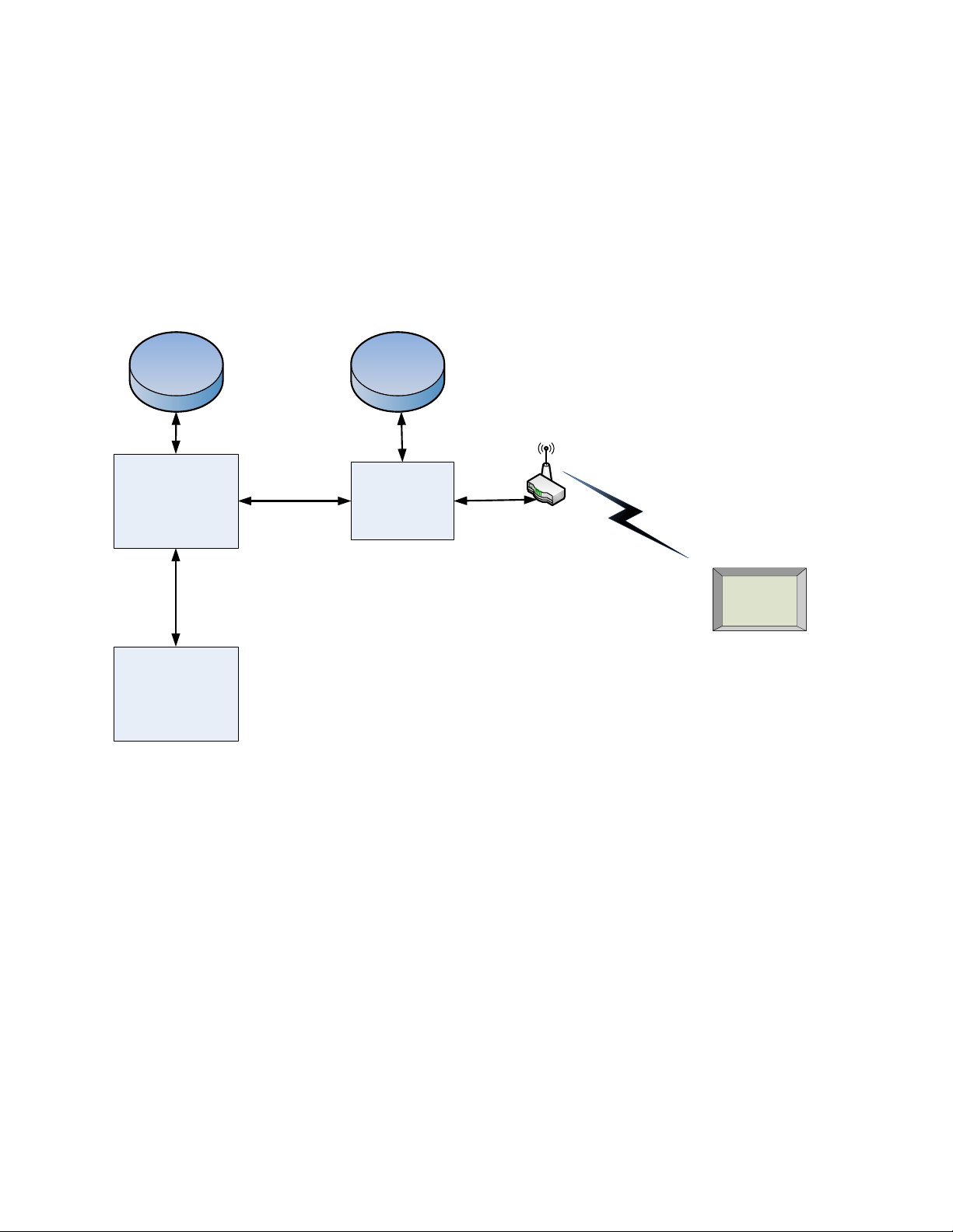
The steps for commissioning the Meeting Room Display Tablet are managed through a versatile
Book Now Application (BNA) [1]. BNA provides an interface that guides the user through the
steps to commission the Tablet and allocating it to a meeting room. BNA registers the Tablet
onto the Network server using the unique identifier (EUI) of the Tablet. A high-level diagram of
the Meeting Room Display Tablet’s infrastructure is shown in Figure 2-1. It is recommended to
refer to the BNA user guide [1] for detailed instructions on commissioning the Tablet.
Facility DB
Mail server
(Calendar)
Book Now
Application (BNA) Network Server
Device DB
Meeting Room
Tablet
Gateway
LoRa
Figure 2-1: Meeting Room Display Tablet’s infrastructure
2.1 Power Up/Down Procedure
Battery powered version of Tablet is shipped with the batteries installed along with pull
tabs that prevent the Tablet from turning on during shipment.
Once the Tablet is configured on the BNA, turn on the Tablet by removing the battery
pull tabs or providing external power depending on the model.
See section 5.3 for LED behaviour during boot-up.
To turn off the Tablet the batteries or external power must be removed. The unit must
remain un-powered for 1 minute to completely reset.
The reset switch of the Tablet is accessible through a pin hole in the bottom side of the
Tablet as shown in Figure 1-2. See section 5.3 for LED behaviour during boot-up.

Meeting Room Display Tablet User Guide T0006377_UG Version 0.5
TEKTELIC Communications Inc. Confidential Page 13 of 28
3Installation
3.1 Included Product and Installation Material
The following items are shipped with each Tablet:
Meeting Room Display Tablet
5V AC-DC power adapter (optional)
Four AA batteries (optional)
Wall mount plate
Security/Lock screw (T6)
Product Manual
3.2 Safety Precautions
The following safety precautions should be observed:
The Tablet is for indoor use only. Do not connect Tablet to any outdoor cables.
The Tablet has no internal field serviceable parts other than the batteries. Other than
installing or replacing the batteries, the Tablet must only be opened by an approved
TEKTELIC service center.
All installation practices must be in accordance with the local and national electrical codes.
Ensure that the Tablet is located to eliminate any physical hazard to people or property.
The Tablet shall be powered from the supplied AC-DC power adaptor or through Power over
Ethernet (PoE) or 4xAA batteries. Simultaneous application of power through more than
one input may result in unexpected operation and shall be avoided.
Keep batteries away from the reach of children.
Do not mix old and new batteries.
If the Tablet is not expected to be used for extended periods of time, the batteries should
be removed before storage to avoid any leak.
3.3 Unpacking and Inspection
The following should be considered during the unpacking of a new Meeting Room Display
Tablet:
Inspect the shipping carton and report any significant damage to TEKTELIC.
Unpacking should be conducted in a clean and dry location.

Meeting Room Display Tablet User Guide T0006377_UG Version 0.5
TEKTELIC Communications Inc. Confidential Page 14 of 28
Do not discard the shipping box or inserts as they will be required if a unit is returned
for repair.
3.4 Equipment Required for Installation
The following tools are required to install the Meeting Room Display Tablet:
1) Screwdriver
2) 4x M4 Screws (Choose screw type based on mounting surface)
3) Spirit level
4) T6 Torx driver for the security/lock screw
3.5 Meeting Room Display Tablet mounting
Meeting Room Display Tablet features a removable mounting plate that simplifies the
installation and leveling of the Tablet. Once the mount plate is installed the Tablet slides onto
the four hooks on the plate. Tablet can be mounted in Landscape or Portrait
3
mode.
Note: The mounting surface must be capable of holding > 15 kg [33 lbs].
Mounting the wall plate
Thread the Ethernet and/or Power cables through the rectangular opening in the wall
plate. Ensure that the lock screw feature marked as “C” in Figure 3-1 is facing away
from the mounting surface.
Secure the mount plate on the mounting surface using 4 x M4 screws in locations A or B
as shown in the Figure 3-1.
oDouble sided adhesive tape could be used when mounting on glass
The slots provided on mount plate allows for adjustment to level the mount plate.
Using a spirit level, ensure that the mounting plate is plumb before tightening all the
screws.
Connect cables
With the externally powered version, connect the necessary cables to the Tablet
(Ethernet, 5V DC and Debug USB port are accessible under the battery cover).
No cables are required on the battery powered version.
Cables can be routed through the channels on the back of the Tablet.
3
Portrait mode is not supported in current version of firmware
Meeting Room Display Tablet User Guide T0006377_UG Version 0.5
TEKTELIC Communications Inc. Confidential Page 15 of 28
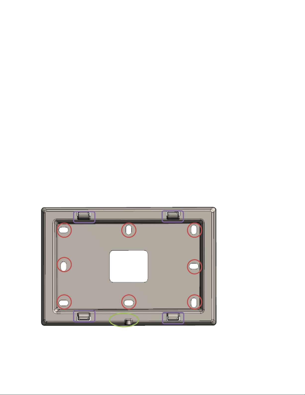
Install the Tablet
Take a note of the MAC-ID/ EUI shown on the label on the back of the Tablet.
To install the Tablet, first align the hooks on the mounting plate to the slots on the back
of the Tablet (See features marked as “D” in Figure 3-1 and Figure 3-2), then push the
Tablet onto the plate. Slide the Tablet to fix the Tablet in place.
It is recommended to proceed with the commissioning steps detailed in Commissioning
before completing the final step of securing the Tablet with the lock screw.
Secure the Tablet using the lock screw
With the battery powered version, ensure that the battery shipment tabs are pulled out
before securing the Tablet.
A T6 Torx screw is provided for the security lock. Tighten the lock screw using hand to
secure the Tablet.
Figure 3-1: Wall mount plate.
A
A
A
A
B
B
B
B
C
D
D
D
D

Meeting Room Display Tablet User Guide T0006377_UG Version 0.5
TEKTELIC Communications Inc. Confidential Page 16 of 28
Figure 3-2: Tablet back side
3.6 Battery Replacement
The following tools are required to install the Meeting Room Display Tablet:
1) A Philips Screwdriver (#2)
2) 4x AA batteries (LiFES2 –Energizer, part number: L91)
Steps for replacing the batteries are as follwos:
Removed the battery cover by removing two philips screws shown in Figure 1-3
Remove all the old batteries from the device.
To turn off the device the batteries must be uninstalled and remain un-powered for 1
minute.
Replace with all new batteries of the recommended type.
Install the battery cover and philips screws to secure the batteries.
See section 5.3 for LED behaviour during boot-up.
Recycle the used batteries when possible by dropping them off at a participating
reatiler.

Meeting Room Display Tablet User Guide T0006377_UG Version 0.5
TEKTELIC Communications Inc. Confidential Page 17 of 28
4Graphical User Interface
The Meeting Room Display Tablet is equipped with a 6-inch EPD Touch Screen that enables users to book, extend or finish a
meeting. The Tablet displays the details of current and next meeting for the room.
The graphical user interface (GUI) features are discussed next. The user interface flow can be divided into two tracks, one when the
room is available for booking and one when the room is occupied.
4.1 Available
When the room is available for booking, the GUI uses a light background as shown in Figure 4-1. The LEDs light up with green color in
the supported models. In Available state the GUI provides following options:
Displays the Next meeting information: Meeting start time and booked by
Button to book a meeting now for specified duration
oTablet makes the booking through a LoRa message to the BNA. The BNA ensures that the room is available for the
specified duration and makes a booking in the configured calendar.
oA confirmation message is displayed showing if the booking was successful or unsuccessful.

Meeting Room Display Tablet User Guide T0006377_UG Version 0.5
TEKTELIC Communications Inc. Confidential Page 18 of 28
Figure 4-1: Room Available –User interface flow

Meeting Room Display Tablet User Guide T0006377_UG Version 0.5
TEKTELIC Communications Inc. Confidential Page 19 of 28
4.2 Occupied
When the room is occupied, the GUI uses a dark background as shown in Figure 4-3. The LEDs light up with red color in the
supported models.
In Occupied state the GUI provides following options:
Displays the current meeting information: Meeting ‘end time’and ‘booked by ‘
Displays the Next meeting information: Meeting ‘start time’and ‘booked by ‘
Button to finish the current meeting.
Button to extend the current meeting for a specified duration.
oThere must be at least 10 minutes in between bookings to be allowed to extend the current meeting.
Button to book a meeting for next available time.
oTablet makes the booking through a LoRa message to the BNA. The BNA ensures that the room is available for the
specified duration and makes a booking in the configured calendar.
oA confirmation message is displayed showing if the booking was successful or unsuccessful.
Figure 4-2: Room Occupied state

Meeting Room Display Tablet User Guide T0006377_UG Version 0.5
TEKTELIC Communications Inc. Confidential Page 20 of 28
Figure 4-3: Room Occupied –User interface flow
Other manuals for T0006086
1
This manual suits for next models
1
Table of contents
Other TEKTELIC Communications Tablet manuals


