tekton 46845 User manual

OPERATOR’S MANUAL
WARNING: BEFORE USE, READ AND UNDERSTAND OPERATOR'S MANUAL. Wear impact-resistant
protective eyewear in work area at all times. This reel must only be mounted to a load bearing structural object
such as a stud, rafter, or floor which can support the combined weight of reel and hose and can withstand pulling
forces on hose when in use. Air hose is designed for use on regulated air compressor systems. DO NOT
EXCEED MAXIMUM WORKING PRESSURE. Be sure to restrain hose as it rewinds—do not allow hose to
rewind at full speed. Never exceed air pressure rating for any air tool. Read and follow all air tool owner’s manuals
and instructions. Certain air tools, such as paint spray guns, sanders, grinders, and sandblasting equipment,
present specific dangers and hazards. Consult applicable material safety data sheet for precautions and possible
respirator recommendation.
CALIFORNIA WARNING: This product contains chemicals known to the State of California to cause birth defects
or other reproductive harm. Please wash hands thoroughly after handling.
STORE THIS MANUAL IN A SAFE
PLACE FOR FUTURE REFERENCE
®
Model #s
46845, 46848
Save time, contact us first.
888-648-8665
NEED HELP?
!
?
AUTO REWIND AIR HOSE REEL
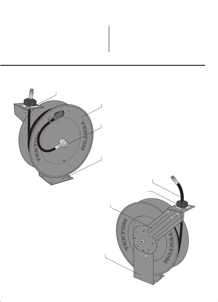
Air Hose
Hose Stopper
page 2
For complete parts diagram, see
page 6-7, centerfold of book
Guide Arm
Support Leg
Air Inlet Valve
Guide Roller
Collar
Drum
Base
Model # 46848
• Air Hose Size: 1/2" x 50'
•Reel Air Inlet (F): 1/2" NPT
•Air Hose Outlet (M): 1/2" NPT
•Max Working Pressure: 250 PSI
•Maximum Air Flow: 35 CFM
Model # 46845
• Air Hose Size: 3/8" x 50'
•Reel Air Inlet (F): 1/4" NPT
•Air Hose Outlet (M): 1/4" NPT
•Max Working Pressure: 250 PSI
•Maximum Air Flow: 25 CFM

OPERATING AIR HOSE REEL
BEFORE MOUNTING AIR HOSE REEL, please take a few minutes to understand how the reel works. Practice operating
the hose reel a few times, pulling hose out and retracting it back onto reel. This will familiarize you with basic functions
and can help you understand where best to mount the air hose reel.
This air hose reel automatically retracts air hose using an internal spring motor. When hose is pulled from reel, it is pulled against
the tension of the spring motor. The more hose is pulled out, the greater the tension built up in spring motor. NEVER LET GO OF
HOSE WHILE PULLING FROM REEL. Letting go will allow hose to rewind at uncontrolled speed, possibly damaging the internal
spring or guide collar.
1. Grasp air hose and pull slowly from reel. As hose is pulled from reel, the entire reel drum rotates. To prevent extra wear on air
hose, periodically check to be sure guide rollers inside collar are rolling smoothly.
2. As reel drum rotates, the locking gear and pawl make a short series of four clicking sounds each 1/2 revolution. In one
revolution, there are a total of eight locking positions.
3. TO LOCK REEL IN POSITION, slow down pulling motion as desired length of hose is reached. While slowly pulling, listen for
each short series of clicking sounds. As the reel is clicking, stop pulling hose and decrease tension. Reel should lock in
position.
TO RETRACT HOSE ONTO REEL, slowly pull hose out until the first series of clicks stops. This means the locking pawl has
cleared the locking gear. DO NOT LET GO OF HOSE! Slowly allow hose to rewind onto reel until hose stopper rests against
guide collar.
page 3
Locking pawl
Locking gear
PULL
DO NOT PULL HOSE OUT BY
GRASPING ATTACHED TOOL.
This will damage air hose. Pull
only by grasping air hose itself.
1 2
3
R
O
T
A
T
E
page 4
MOUNTING HOSE REEL
Choosing a Location
DO NOT MOUNT HOSE REEL OUTDOORS OR ON VEHICLE. This hose reel is not designed to resist constant
exposure to weather or continuous vibration. Mount under cover in an area not directly exposed to weather.
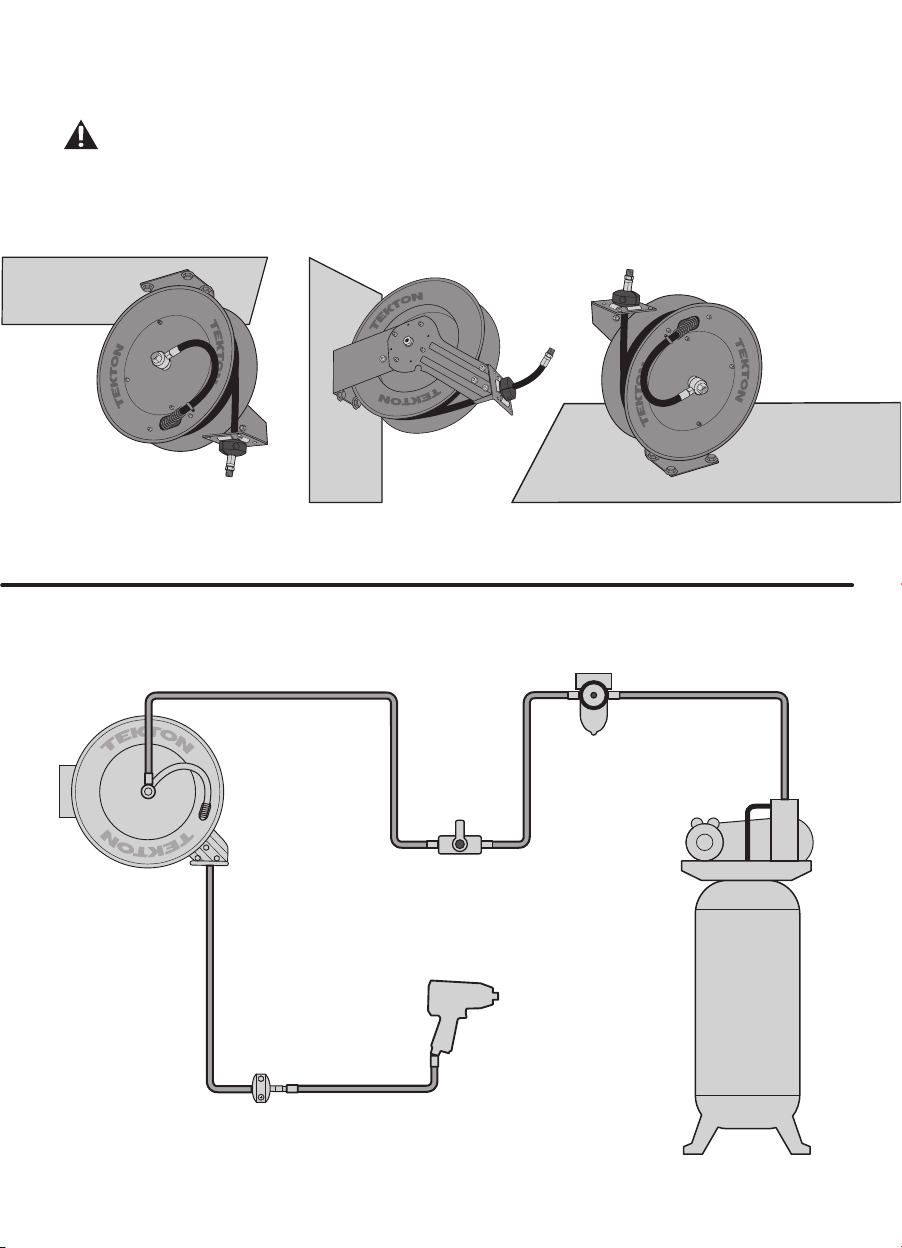
Reel can be mounted on the floor, ceiling, or wall, wherever it is convenient. When choosing a location, remember that you
can only mount reel to a load-bearing structural member capable of supporting combined weight of reel, hose, and
forces caused by pulling or manuevering hose. Mounting reel near air compressor may be desirable since you can connect
the two with a shorter, less expensive length of hose. Also, air compressor controls will be conveniently nearby.
FLOOR
CEILING
WALL
COMPRESSOR
WHIP HOSE
TOOL
SHUTOFF VALVE
REGULATOR
MOISTURE TRAP
LUBRICATOR
AIR
HOSE
REEL
Typical Compressed Air System

1. Use included mounting template to mark hole locations.
Use a level to position template. Tape securely in position
before marking. Remove template when finished.
3. Pre-install lower pair of hardware and tighten down leaving
just enough space to snugly fit base.
4. Hang hose reel by sliding slotted base onto pre-installed
hardware. Carefully let go of hose reel, making sure its
weight is being supported. Hose reel should support itself
in this position long enough to install remaining hardware.
5. Immediately install second set of hardware. Tighten all
hardware until snug. Do not overtighten.
CAUTION: CEILING MOUNTING REQUIRES TWO PEOPLE. DO NOT
ATTEMPT TO MOUNT HOSE REEL TO CEILING BY YOURSELF. USING
A LADDER CAN BE DANGEROUS AND IS NOT RECOMMENDED.
1. Use included mounting template to mark hole locations. Tape securely in position
before marking. Remove template when finished.
2. Drill holes for bolts. Keep drill steady and in line with hole to prevent wobbling and
enlarging of hole.
3. Pre-install one pair of hardware and tighten leaving just enough space to fit base.
4. Hang hose reel by sliding slotted base onto pre-installed hardware. DO NOT LET
GO OF HOSE REEL!
5. While continuing to support reel, install second pair of hardware. Tighten all
hardware until snug. Do not overtighten.
1. Use included mounting template to mark hole locations. Tape securely in
position before marking. Remove template when finished.
2. Drill holes for bolts. Keep drill steady and in line with hole to prevent
wobbling and enlarging of hole.
3. Set reel in position, aligning base with holes. Install all hardware,
tightening until snug. Do not overtighten.
CEILING
WALL
FLOOR
MOUNTING TEMPLATE
2. Drill holes for bolts. Keep drill steady and in line with hole to
prevent wobbling and enlarging of hole.
WOOD - Lag bolt,
lock washer, and
washer
4X 4X 4X
METAL - Bolt, two
washers, lock washer,
and nut
MASONRY - Bolt, lock
washer, washer, and
anchor
page 5
ATTENTION - Mounting bolts
can loosen with heavy use or over
time. Check condition of mounting
bolts every 6 months.

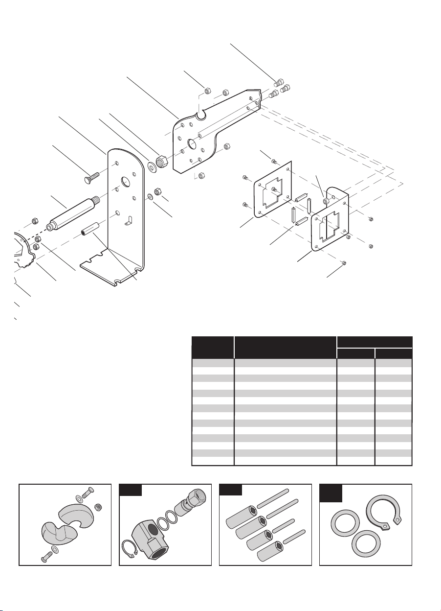
1. Main Spring Cover - Outside
2. Main Spring
3. Main Spring Cover - Inside
4. Drum - Outside
5. Drum - Inside
6. Support Leg and Base
7. Guide Arm
8. Hose Guide Collar
9. Back Plate
10. Rollers (4) & Pins (4)
11. Air Inlet Valve
12. Swivel Connector
13. Retaining Ring
14. Washer
15. Nut (4)
16. Bolt (4)
17. Nut (4)
18. Hose Clamp
19. Bolt
20. Nut
21. Carriage Bolt (3)
22. Nut (3)
23. Axle
24. Washer
25. Nut
26. Locking Gear Hub
27. Locking Gear
28. Locking Pawl
29. Locking Pawl Axle
30. Locking Pawl Spring
31. Spacer
32. Washer
33. Nut
34. Carriage Bolt (4)
35. Nut (4)
36. Bolt (3)
37. Nut (3)
38. Bolt (4)
39. Nut (4)
40. Hose Stopper
41. Bolt (2)
42. Washer (2)
43. Nut (2)
44. Air Hose
45. Bend Restrictor
P
ARTS
L
IST
page 6
1
16
11
23
4
5
17
12
13 14
20
19
18
21
26
2928
30
15
99001 99002
99040
45
43
40
41
44
42
99006 99018 99041
99042
page 7
23
34
25
24
35
36
6
7
26
29
22
28
30
27 31
32
33
38
37
8
10
9
39
ASSEMBLY DESCRIPTION
99001 3/8" Air Inlet Assembly
99002 Locking Pawl Assembly
99003 Guide Collar and Roller Assembly
99004 3/8" Hose Stopper Assembly
99005 Main Spring Canister Assembly
99006 1/2" Air Inlet Assembly
99007 1/2" Hose Stopper Assembly
99008 3/8" x 25' Air Hose
99009 3/8" x 50' Air Hose
99010 1/2" x 50' Air Hose
99018 Guide Rollers and Pins
99040 Locking Pawl Assembly
99041 3/8" O-Ring Kit
99042 1/2" O-Ring Kit
FITS THIS HOSE REEL
46845
•
•
•
•
•
•
•
•
46848
•
•
•
•
•
•
•
•

page 8
MAKING ADJUSTMENTS
Adjusting the Guide Arm
1. Pull out 3-4 feet of hose and
lock reel in position.
3. Rotate guide arm to one of five positions desired. Replace four bolts and tighten.
2. Remove the four bolts connecting
guide arm to base.
12
34
Assemble bolts
as shown
BASE
GUIDE ARM
OUTSIDEINSIDE
1
4 5
2 3
page 9
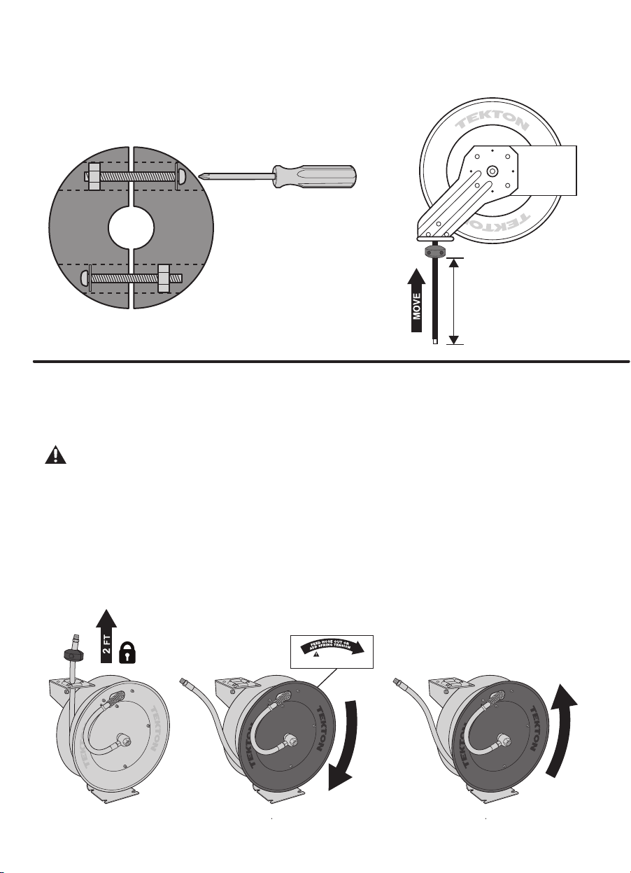
Adjusting Recoil Tension
Hose reel is shipped with spring tension properly set. Be aware that spring tension is calibrated to retract entire length of air
hose. If you are working with only part of the air hose length, recoil action may seem slower than expected. However, if you feel
hose rewinds too quickly or too slowly, you can easily adjust the tension of the main recoil spring by simply turning the reel drum
to a new "home" position.
DO NOT SET TOO MUCH TENSION IN SPRING. Damage to spring could result.
1. Disconnect incoming air supply.
2. Pull out about two feet of hose and lock reel in position.
3. Remove hose stopper. Pull hose backward through hose guide.
4. While firmly gripping edge of reel drum, turn reel clockwise (as viewed from air inlet side) just enough to release locking pawl.
DO NOT LET GO OF REEL DRUM, or it will spin uncontrolled until all spring tension is lost.
To Increase Tension: Turn reel drum clockwise until desired tension has been added. Lock reel in nearest locking position.
To Decrease Tension: Allow reel drum to slowly turn counterclockwise until extra tension has been released. Lock reel in
nearest locking position.
5. Feed hose through hose guide. Re-attach hose stopper.
6. Connect incoming air supply.
Adjusting Hose Stopper Position
The hose stopper determines the length of hose that remains outside of reel. To adjust stopper position, first pull
hose out past the desired position of hose stopper. Lock reel in position. Loosen (but do not remove) both stopper
bolts just enough so stopper can slide along hose. Move stopper to desired position. Tighten stopper bolts until
hose stopper cannot slide. Do not overtighten bolts.
Loosen but do not
remove bolts
D
E
C
R
E
A
S
E
I
N
C
R
E
A
S
E
See label
DO NOT OPEN THIS COVER!
Spring motor inside is under tension.
CAUTION
Desired length
of hose

DO NOT
TURN
page 10
ATTACHING INCOMING AIR
For maximum leak-free performance, air inlet valve is made of solid brass. Brass is a soft metal and overtightening or rough
handling can cause damage or breakage. Use care when working with air inlet valve. For a tight, leak-free connection, follow all
instructions carefully.
Option 1
Wrap incoming hose end with thread sealing tape. AIR INLET VALVE CANNOT ROTATE, do not attempt to turn. To prevent
rotation, hold air inlet valve with wrench to stabilize it while connecting air hose. Thread air hose into air inlet valve. Using second
opposing wrench, tighten connection just until snug.
Option 2
Locate included 90˚ connector. Wrap threaded end with thread sealing tape. AIR INLET VALVE CANNOT ROTATE, do not
attempt to turn. To prevent rotation, hold air inlet valve with wrench to stabilize it while connecting air hose. Thread 90˚ connector
into air inlet valve. Using second opposing wrench, tighten connection just until snug. Next, wrap incoming hose end with thread
sealing tape. Thread into swivel end of 90˚ connector. Using two opposing wrenches, tighten connection just until snug.
To ensure optimum performance and efficiency, check all connections for leaks. With air system pressurized, brush
each connection with soapy water. Inspect closely. Air bubbles indicate leaking air. Tighten any leaking fittings.
OPTION 1
Incoming
Air
0º
OPTION 2
Incoming
Air
90º
46848
air inlet design
DO NOT
TURN
page 11
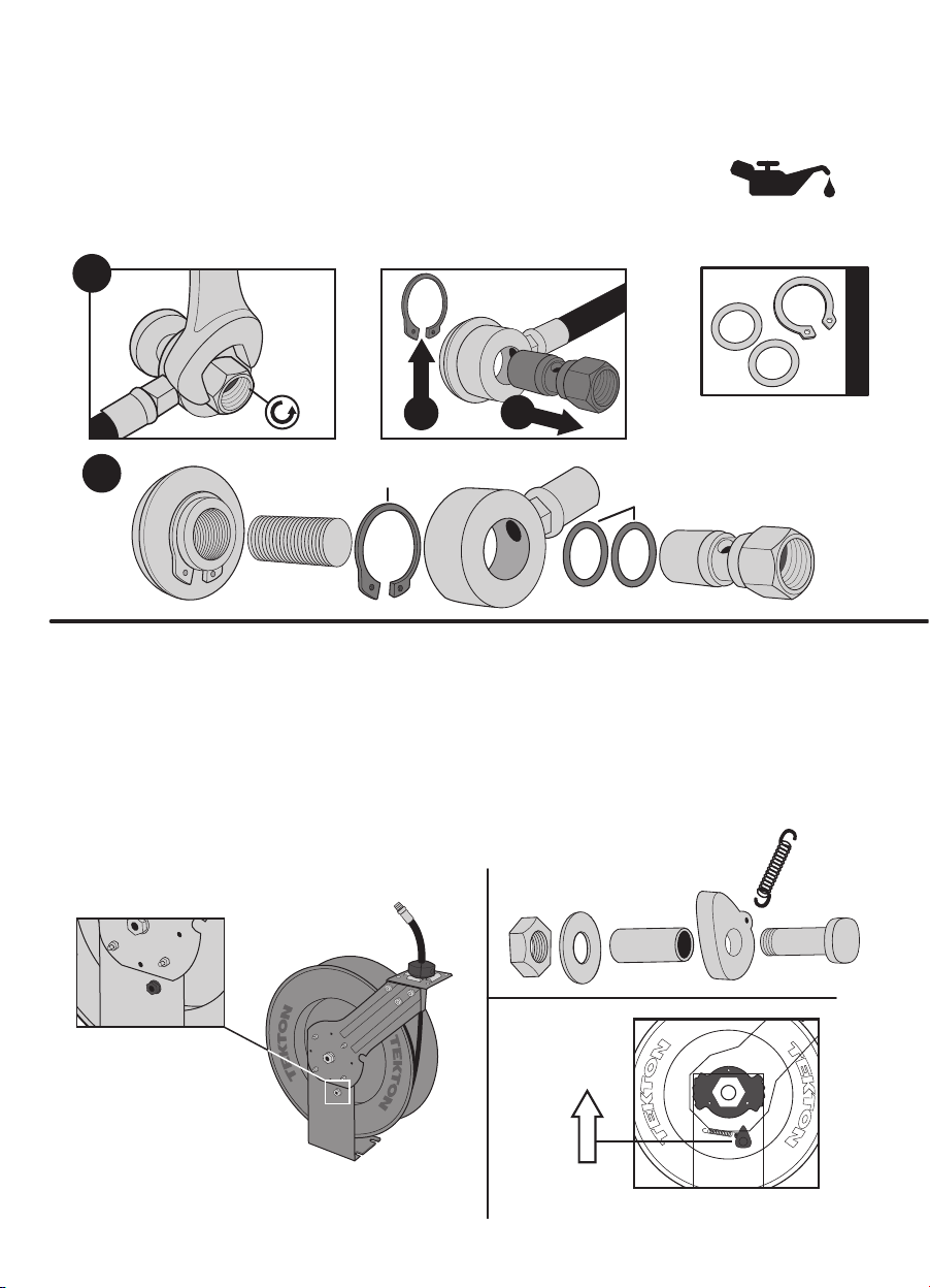
Replacing Air Inlet Valve O-rings
The O-ring seals inside the air inlet valve assembly wear over time. If leaking around air inlet valve
is observed, O-rings should be replaced. An O-ring replacement kit is shipped with this hose reel.
Store in a safe place for future use.
1. Disconnect incoming air supply. Unscrew air inlet valve assembly (part 11) from axle
(part 23) by fitting wrench onto hex portion of valve and turning counterclockwise.
2. Remove retaining ring (part 13) and slide air inlet valve swivel connector (part 12) off
from swivel connector.
3. Remove worn O-rings from air inlet valve and replace with new parts.
Reverse above procedure to re-assemble.
INCLUDED KIT
For easy installation and
best seal, thinly coat
O-rings with petroleum jelly.
Replacing Locking Pawl
Sometimes with heavy use, the locking pawl can begin to wear causing poor engagement with ratchet teeth. This can result in
slipping or difficulty locking. It is easy to replace and can be done while hose reel is mounted.
1. Reel should be in fully retracted position ("home"), with hose stopper resting against guide roller collar. Be sure locking pawl
is not engaged with ratchet teeth, and that there is enough clearance between pawl and teeth to allow free and easy removal
and installation of locking pawl assembly.
2. Unhook return spring from anchor point. Loosen and remove lock nut. Remove old locking pawl assembly from support leg.
3. Insert new locking pawl assembly through support leg. Thread on lock nut and tighten until snug. Hook end of return spring
through anchor point.
4. Verify function of locking pawl by pulling hose out and locking reel in position.
Stop pawl nut
Install stop pawl
pointed toward
center of reel
Retaining Ring
O-Rings
3
1
2a 2b

This manual is the sole property of Michigan Industrial Tools. No part
of this manual, may be reproduced in any form, without the express
written consent of Michigan Industrial Tools.
© Copyright 2015
Michigan Industrial Tools
WWW.TEKTON.COM
Michigan Industrial Tools
3707 Roger B Chaffee SE
Grand Rapids, MI 49548
Printed in China
Replacing Hose
If hose becomes damaged, it may be necessary to replace it. In most cases, air hose can be replaced while reel is
still mounted. Replace air hose with same diameter and length of original hose. Installing a longer or shorter
hose will require Adjusting Recoil Tension (page 9).
1. Disconnect incoming air supply. Pull out about 1 foot of hose and lock reel in position. DO NOT UNLOCK HOSE
REEL during this installation process. If reel becomes unlocked, it will spin at uncontrolled speed, possibly
resulting in damage to internal spring.
2. Remove hose stopper. Pull hose backward through guide roller collar. Unwrap (counterclockwise, when viewed
from air inlet side) until reel is empty.
3. Remove hose clamp. Save for re-installation. Disconnect hose end from air inlet assembly. Pull hose end back
through slot in reel drum. Remove spring guard from old hose.
4. Place spring guard on new hose. Feed hose end through slot in reel drum. Wrap end of new hose with thread
sealing tape. Connect to air inlet assembly. Re-install hose clamp. Make sure spring guard is aligned correctly in
slot to protect hose from sharp metal edges.
5. Wrap hose around reel (clockwise) until 1-2 feet of hose remains.
6. Feed hose end through guide roller collar. Re-attach hose stopper in desired position. Unlock hose reel
and rewind until hose stopper rests against guide roller collar. Connect incoming air supply.
1 YEAR REPLACEMENT GUARANTEE
This product is guaranteed for 1 YEAR. If it does not meet your expectations, we will replace
it or provide replacement parts free of charge. To arrange for shipping of your replacement
us at 1-888-648-8665. Please have receipt or other proof of purchase available.
1
4
DO NOT OPEN THIS COVER!
Spring motor inside is under tension.
CAUTION
See label
W
R
A
P
5 6
U
N
W
R
A
P
2 3
This manual suits for next models
1
Table of contents
Other tekton Tools manuals


