manuals.online logo
Brands
  1. Home
  2. •
  3. Brands
  4. •
  5. Giovenzana
  6. •
  7. Tools
  8. •
  9. Giovenzana TR85H7P User manual

Giovenzana TR85H7P User manual

…come non perdere la garanzia
...how to keep your warranty
…
условия
гарантии
MI07PYRU –rev.00/2017
TR85H7P
Mounting instructions
TR85H7P continuous conductors
Инструкции по монтажу и Паспорт
TR85H5P с медной шиной на протяжку
Istruzioni montaggio
TR85H7P conduttori continui
ENG
RUS
ITA
-
-
-
GIOVENZANA INTERNATIONAL
nella continua ricerca di miglioramento dei propri prodotti si riserva il
diritto di apportare, senza obbligo di preavviso, tutte le modifiche tecniche
e funzionali contenute nel presente manuale.
MI07PYRU- rev.00/2017
GIOVENZANA INTERNATIONAL
in its continuous quest for product improvement, reserves the right to change
any of the technical and functional information in this manual without prior
notice.
MI07PYRU- rev.00/2017
GIOVENZANA INTERNATIONAL
находится впостоянном поиске
усовершенствования своей продукции, оставляет
за собой право вносить любые технические и
функциональные изменения внастоящую
инструкцию, без обязательства опредварительном
уведомлении.
MI07PYRU- rev.00/2017
Revisione
Revision
Ревизия
Data
Date
Дата
Descrizione
Description
Описание
00
12/07/2017
Emissione
First issue
Выпуск
MI07PYRU –rev.00/2017 2
MI07PYRU –rev.00/2017 3
Indice
Contents
Оглавление
1
Premessa
Introduction
Вступление
4
2
Dati identificazione prodotto
Product identification data
Идентификационные данные продукции
5
3
Descrizione prodotto
Product description
Описание продукции
6
4
Legenda simboli usati
Symbols legend
Легенда используемых символов
7
5
Disposizione conduttori rame
Arrangement of the copper conductors
Расположение медных проводников
8
6
Caratteristiche tecniche
Technical specifications
Технические характеристики
9
7
Sicurezza
Safety
Безопасность
10
8
Garanzia
Warranty
Гарантия
11
9
Installazione linea:
Line Installation:
Установка линии
12
9.1
Fissaggio mensole
Bracket fixing
Крепление кронштейнов
13
9.2
Fissaggio sospensioni
Hanger installation
Крепление подвесных скоб
15
9.3
Punto fisso
Fixed point
Точка фиксации
16
9.4
Montaggio barre
Rail mounting
Монтаж секций шинопровода
17
9.5
Giunzioni
Joints
Соединительные муфты
19
9.6
Inserimento conduttori
Conductor insertion
Протяжка медной шины
21
9.7
Alimentazione di testa
Head feed
Концевой подвод питания
24
9.8
Montaggio ultima barra
Installation of last rail
Монтаж последней секции шинопровода
27
9.9
Carrelli
Trolleys
Токосъемники
28
9.10
Collegamento parallelo carelli
Trolley’s parallel connection
Параллельное соединение токосъемников
30
9.11
Inserimento guarnizione e chiusura linea
Sealing strip insertion and line termination
Вставка уплотнительной ленты изакрытие линии
33
10
Braccio di traino
Towing arm
Буксирная опора
34
11
Alimentazione intermedia
In-line feed
Линейный подвод питания
36
12
Giunto sezionamento
Isolator joint
Изолирующая секция
38
13
Giunto ispezione
Inspection joint
Секция контроля
40
14
Giunto espansione
Expansion joint
Секция расширения
42
15
Prolungamento linea
Line extension
Продление линии
46
16
Montaggio cavo scaldante
Installation of heating cable
Монтаж подогревающего кабеля
48
17
Manutenzione
Maintenance
Техническое обслуживание
49
18
Risoluzione dei problemi
Troubleshooting
Решение проблем
50
1
PREMESSA
Questo manuale contiene tutte le istruzioni necessarie per una corretta posa e messa in servizio della
linea di alimentazione serie TR85H7P (profilo “H” scatolato).
Le operazioni contenute in questo manuale devono essere eseguite da personale specializzato e
qualificato.
Necessaria:
conoscenza di norme generali circa la sicurezza
conoscenza di norme circa prevenzione infortuni
conoscenza di norme circa installazioni elettriche
competenza nell’ usare attrezzature elettriche
L’ installatore ha l’ obbligo di seguire queste istruzioni in modo da assicurare un funzionamento
duraturo e costante nel tempo come pure garantire sicurezza nell’ utilizzare questo prodotto.
La non osservazione di queste istruzioni può comportare seri danni sia all’ apparecchiatura stessa, sia
all’ operatore.
In caso di installazioni straordinarie e/o che richiedono una diversa configurazione non presente in
questo manuale si prega di rivolgersi immediatamente al supporto tecnico GIOVENZANA
INTERNATIONL B.V.
Qualsiasi disegno o documento addizionale specifico contenuto nel componente fornito prende
priorità su questo manuale.
ВСТУПЛЕНИЕ
Данное пособие включает всебя все необходимые инструкции по
установке иподключению линии питания серии TR85H7P.
(шинопровод сдвойным корпусом).
Все действия, описанные вданном пособии, должны быть
выполнены специализированным иквалифицированным
персоналом.
Требуются:
общие знания норм безопасности
общие знания по предотвращению травмоопасных ситуаций
знание норм по установке электрического оборудования
компетентность виспользовании электрического оборудования
Монтажник обязан следовать инструкциям для обеспечения
долговечной истабильной работы линии игарантии безопасности в
использовании данного изделия.
Невнимательное изучение инструкций может привести ксерьезным
повреждениям оборудования итравмам обслуживающего
персонала.
Вслучае необходимости дополнительных установок и/или
изменения конфигурации, не присутствующих вданном пособии,
следует незамедлительно обратиться кслужбе Технической
Поддержки GIOVENZANA INTERNATIONAL B.V.
Любой чертеж или дополнительный уточненный документ,
предоставленный вместе сизделием, имеет приоритет над данным
пособием.
INTRODUCTION
This manual contains all the necessary instructions for the correct installation and commissioning of the
TR85H7P series busbar system.
(“H” honeycomb profile)
The operations described in this manual must be performed by fully qualified and specialized personnel.
Requisites:
knowledge of general safety regulations
knowledge of accident prevention regulations
knowledge of electrical installation standards
skilled in the use of electrical tools and equipment
The installer is required to follow these instructions in order to ensure both long-term reliable
functioning and safety in using this product.
Non-observance of these instructions may result in both operator injury and/ severe damage to the
equipment.
In the event case of special installations and/or those that require a different configuration not present
in this manual, please contact GIOVENZANA INTERNATIONAL B.V. technical support.
Any additional drawing or document provided with the supplied component takes priority over this
manual.
MI07PYRU –rev.00/2017 4
2
DATI DI IDENTIFICAZIONE
DEL PRODOTTO
Il profilo esterno è marchiato in maniera indelebile e fornisce le seguenti informazioni:
Certificazione:
Posizionamento conduttore di terra:
(la linea continua nera abbinata al simbolo di terra indica chiaramente la posizione del conduttore di terra)
Provenienza: MADE IN ITALY
Produttore: GIOVENZANA Int.
Data di produzione: giorno/mese/anno
Serie: TR85H7P
Colore esterno barra: standard giallo
(su richiesta colori personalizzati)
1
2
3
4
5
6
ИДЕНТИФИКАЦИОННЫЕ ДАННЫЕ
ПРОДУКЦИИ
Внешний профиль помечен несмываемыми надписями и
предоставляет следующую информацию:
Сертификат:
Заземление:
(Черная линия совместно ссимволом заземления указывает на расположения
заземляющего проводника)
Страна-изготовитель: СДЕЛАНО ВИТАЛИИ
Производитель: GIOVENZANA Int.
Дата изготовления: день/ месяц/ год
Серия: TR85H7P
Цвет корпуса шинопровода: стандарт- желтый
(другие цвета на заказ)
1
2
3
4
5
6
PRODUCT IDENTIFICATION
DATA
The busbar rail is indelibly marked on the outside and provides the following information:
Certification:
Positioning of earth conductor:
(the continuous black line combined with the earth symbol clearly indicates the position of the earth conductor)
Place of origin: MADE IN ITALY
Manufacturer: GIOVENZANA Int.
Date of manufacture: day/month/year
Series: TR85H7P
External rail colour: standard yellow
(personalized colours upon request)
1
2
3
4
5
6
MI07PYRU –rev.00/2017 5
1 2 3 4 5 6
3
DESCRIZIONE PRODOTTO
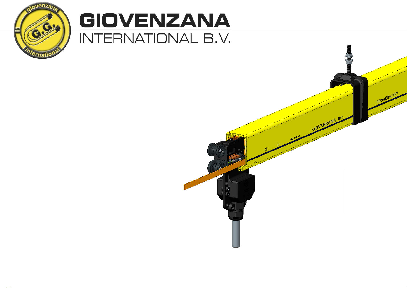
La linea di alimentazione isolata TR85H7P è un sistema moderno e antinfortunistico per la
trasmissione di energia per vari tipi di utenze mobili: gru, carriponte, paranchi, sistemi a nastro..
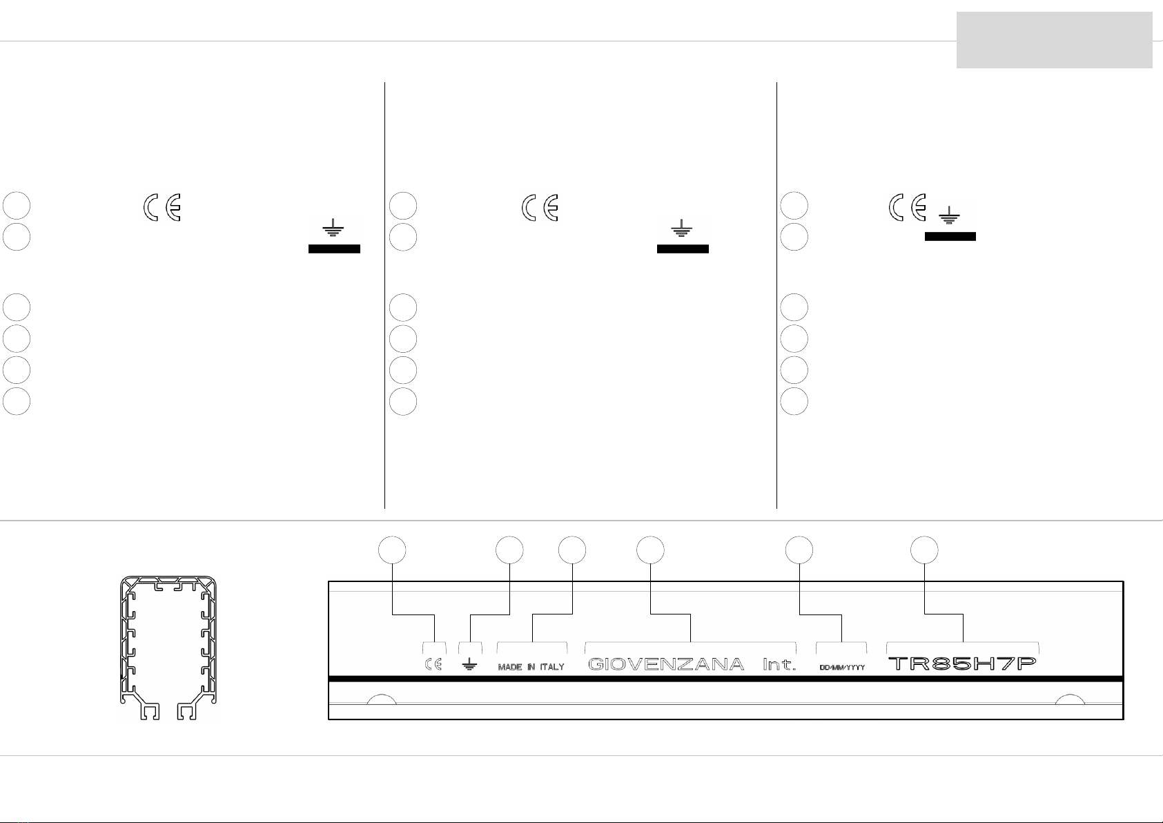
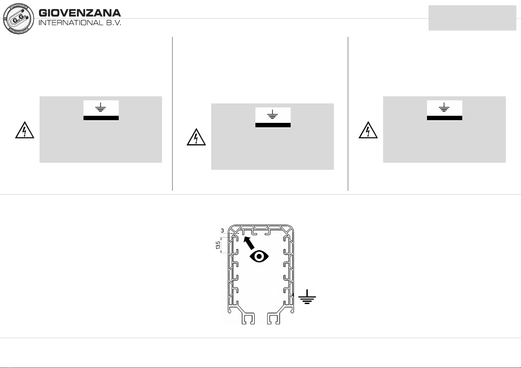
La linea è costituita da un involucro in PVC scatolato “H” ossia realizzato con doppia camera che ne
conferisce una maggiore rigidezza rispetto un profilo estruso pieno.
La misura standard delle barre è di 3 e 4 metri.
Ogni conduttore di ciascuna barra viene giuntato al suo corrispettivo della barra adiacente tramite
appositi morsetti in modo da garantire una connessione elettrica sicura ed affidabile.
Ogni barra è collegabile l’ una all’ altra mediante placche di congiunzione e sostenuta mediante
supporti e a seconda della tipologia di linea, sarà composta da una alimentazione di testa oppure un’
alimentazione intermedia sulla linea e infine da un tappo (due se tipologia con alimentazione
intermedia) di chiusura linea.
La trasmissione elettrica è affidata ad uno o più carrelli completamente isolati che scorrendo all’
interno della barra non lasciano esposte parti elettriche in tensione. La conducibilità elettrica è
garantita da spazzole in metal-grafite che assicurano prestazioni, minime cadute di tensione e
affidabilità di servizio nel tempo. Inoltre i carrelli sono provvisti di ruote per cui scorrono senza
attrito all’ interno del profilo e predisposti per accogliere un supporto/staffa di traino che collegato all’
utenza mobile permette di trascinare il carrello parallelamente ad essa.
Per l’installazione all’ aperto o in zone particolarmente polverose, la barra è predisposta per l’
applicazione di una guarnizione in gomma che ne aumenta il grado di protezione.
Giovenzana Int. realizza perfino la versione TR85H7P può accogliere fino a n° 7 conduttori
combinando anche diverse connessioni in parallelo per aumentarne la portata.
ОПИСАНИЕ ПРОДУКЦИИ
Линия троллейных шинопроводов TR85H7P –это современная и
безопасная система передачи электроэнергии для различных типов
оборудования, таких как: тали, мостовые краны, ленточные и
цепные конвейеры ит.д.
Линия представляет собой двойной корпус из ПВХ, что придает ей
большую жесткость всравнении скорпусом обычного
шинопровода. Стандартная длина секций 3 и4 метра.
Проводники на каждой секции соответственно подсоединяются
друг кдругу спомощью специальных стыковочных зажимов, чтобы
обеспечить безопасное инадежное электрическое соединение.
Секции шинопровода подсоединяются друг кдруг спомощью
соединительных муфт иподдерживаются на кронштейнах, В
зависимости от типа линии, шинопровод состоит еще из концевого
или линейного подвода питания изаглушки, замыкающей линию
(две заглушки слинейным подводом питания).
Передача электроэнергии осуществляется посредством одного или
более полностью изолированных токосъемников, которые
передвигаются внутри шинопровода, не оставляя оголенными
токопроводящие части.
Электропроводность обеспечивается металлографитными
щетками, которые гарантируют производительность, минимальные
перепады напряжения инадежность работы на протяжении
длительного времени. Кроме того токосъемники снабжены
роликами, благодаря чему передвигаются внутри шинопровода без
трения. Они предназначены для подсоединения буксирной опоры,
всвою очередь прикрепленной на передвижном механизме, которая
позволяет перемещать токосъемник параллельно самому
механизму.
Для установки линии на открытом воздухе или вособо пыльных
помещениях, шинопровод оснащен выемками для резиновой
уплотнительной ленты, которая повышает степень защиты.
Giovenzana International также реализует версию TR85H7P, вкоторой можно
провести до 7 проводников, комбинируя разные виды подключения
для увеличения мощности.
PRODUCT DESCRIPTION
The TR85H7P insulated busbar line is a modern and safe system for energy transmission on various
types of mobile equipment: cranes, gantries, hoists, conveyor belt systems, etc.
The line consists of a PVC casing made with an “H” honeycomb profile, i.e. made with a double wall
that gives greater stiffness with respect to a solid extruded profile.
The standard rail lengths are 3 and 4 metres.
Every conductor of each rail is joined to its equivalent on the adjacent rail via specially provided
terminal clips to ensure a secure and reliable electrical connection.
Each rail can be connected to another using joint plates and is supported by hangers, while the line,
according to type, will have a head feed or an in-line feed along the line and an end cap (two for the
in-line feed type) for line termination.
The transmission of electricity is provided by one or more fully insulated trolleys that run inside the
bar and without leaving any live parts exposed. Electrical conductivity is guaranteed by metal-graphite
shoes, which ensure good performance, minimal voltage drops and long service life reliability. In
addition, the trolleys are equipped with wheels, allowing them to run friction-free inside the rail, and
designed to engage a tow support/bracket, which, connected to the mobile load, allows towing the
trolley parallel to it.
For installation outdoors or in particularly dusty areas, the rail is designed to accept a rubber sealing
strip that increases the level of protection.
Giovenzana Int. even produces the TR85H7P version, which can accept up to seven conductors, also
combining several connections in parallel to increase capacity.
MI07PYRU –rev.00/2017 6
4
LEGENDA SIMBOLI UTILIZZATI
Qui rappresentati i vari simboli che troverete in questo manuale usati per indicare un’ operazione di
estrema importanza ai fini di sicurezza dell’ operatore e dei componenti stessi della linea.
Pericolo di folgorazione
Leggere attentamente
! Pericolo generale
Messa a terra
Ricontrollo e conferma
SYMBOLS LEGEND
The various symbols used in this manual to indicate operations of major importance regarding the
safety of the operator and line components are listed here.
ЛЕГЕНДА ИСПОЛЬЗУЕМЫХ СИМВОЛОВ
Ниже представлены различные символы, используемые вданном
пособии, для указания на очень важные операции, необходимые для
безопасности сотрудников икомпонентов линии.
Voltage hazard
Read carefully
! General hazard
Protective earth
Check and confirm
Опасность поражения
электрическим током
Читать внимательно
! Опасность
Заземление
Проверка иподтверждение
MI07PYRU –rev.00/2017 7
DISPOSIZIONE
CONDUTTORI DI RAME
Le immagini mostrano la disposizione dei conduttori.
ATTENZIONE:
A titolo preferenziale si attribuisce la posizione del conduttore di neutro nel vano alto della barra
Il conduttore di terra è contrassegnato dalla linea
continua nera e dal simbolo di terra.
5
ARRANGEMENT OF THE
COPPER CONDUCTORS
The pictures shows the position of the
conductors
WARNING:
The position of the neutral conductor is preferably assigned to the upper slot of the rail.
РАСПОЛОЖЕНИЕ МЕДНЫХ
ПРОВОДНИКОВ
На изображениях указано расположение медных
проводников
ВНИМАНИЕ:
Нейтральный проводник преимущественно располагается в
верхнем проеме корпуса шинопровода.
The earth conductor is marked by a continuous
black line and the earth symbol.
Заземляющий проводник
отмечен черной линией и
символом заземления
MI07PYRU –rev.00/2017 8
4
3
2
1
5
6
PE
(N)
6
CARATTERISTICHE TECNICHE: TECHNICAL SPECIFICATIONS: ТЕХНИЧЕСКИЕ ХАРАКТЕРИСТИКИ:
Tabella peso (barra completa di conduttori)
Busbar rail weight table (complete with conductors)
Таблица определения веса шинопровода (с проводником)
50 A
100 A
200 A (*)
160 A
320 A (*)
N° CONDUTTORI
CONDUCTORS NO.
№ ПРОВОДНИКОВ
7
1.60 kg/m
2.20 kg/m
2.95 kg/m
Temperatura ambiente
Ambient temperature
Температура окружающей среды
Esercizio
Operating
Pабочая
Stoccaggio
Storage
Xранения
-30°C … +55°C
-30°C … +70°C
min MAX
(*) The 200 A and the 320 A are obtained by parallel configuration, so only for 4 poles.
MI07PYRU –rev.00/2017 9
(± 50g)
SICUREZZA
Durante le operazioni di installazione o di manutenzione della linea occorre assicurarsi di:
staff composto da almeno due persone.
attenersi al piano di sicurezza sul lavoro.
indossare o utilizzare i dispositivi individuali di protezione previsti dalle norme vigenti.
utilizzare attrezzature di sollevamento (scale, ponteggi, piattaforme elevatrici..) omologate e
rispondenti alle norme vigenti prevenendo situazioni di pericolo durante la movimentazione.
prevedere tutti gli equipaggiamenti di sicurezza in caso di installazione ad altezze elevate.
allontanare le persone estranee all’ installazione della linea.
Operare in assenza di
tensione sulla linea e assicurarsi che in nessun caso
possa essere, anche accidentalmente, messa in
tensione.
7
БЕЗОПАСНОСТЬ
Во время установки или технического обслуживания линии
необходимо убедиться вследующем:
наличие бригады из минимум двух человек.
придерживаться правил безопасности во время работы.
использовать форму исредства индивидуальной защиты,
предусмотренные действующими нормами.
использовать утвержденное исоответствующее действующим
нормам оборудование для подъема (лестницы, леса, подъемные
платформы..), во избежание опасных ситуаций во время
передвижения.
подготовить все необходимое для страховки, вслучае проведения
работ на значительной высоте.
Увести посторонних из зоны установки линии.
SAFETY
Ensure the following during line installation or maintenance operations:
team composed of at least two people.
keep to the safety at work regulations.
wear/use the personal protective equipment provided for by current regulations.
use type-approved lifting equipment (ladders, scaffolding, lifting platforms, etc.) in conformity with
current regulations, and avoid hazardous situations when handling.
provide safety equipment in the case of installation at large heights.
keep persons not involved in line installation away from work area.
Work with power disconnected
from the line and ensure that under no
circumstances can the line be powered up, even
accidentally.
Работа допускается только в
условиях отключенного питания
Убедиться, что напряжение
отключено ине может быть
случайно включено.
MI07PYRU –rev.00/2017 10
CONDIZIONI DI GARANZIA
La durata standard del periodo di garanzia per i prodotti Giovenzana International B.V. è di due anni. La condizione
di garanzia è di tipo carry-in, cioè presso Giovenzana International B.V.
Durante il periodo di garanzia, il Controllo Qualità della Giovenzana International B.V. riparerà eventuali guasti che
risultino da difetti di fabbricazione o di materiali. Se il Controllo Qualità della Giovenzana International B.V. ritiene
impossibile porre rimedio alle suddette mancanze, sostituirà i componenti che, a suo giudizio, hanno la medesima
funzione delle apparecchiature da sostituire, in tal caso la proprietà dei componenti sostituiti sarà di Giovenzana
International B.V.
La garanzia è limitata alla riparazione o alla sostituzione delle parti. Il Controllo Qualità della Giovenzana
International B.V. non è in alcun caso responsabile per ulteriori mancanze o difetti.
Le spese di riparazione e/o sostituzione dei prodotti in garanzia sono a carico della società Giovenzana International
B.V. mentre le spese di trasporto sono a carico del cliente.
Il Cliente deve far pervenire al Controllo Qualità della Giovenzana International B.V. il prodotto con allegato una
spiegazione dettagliata del problema.
L’obbligo di garanzia decade se:
1) il Cliente modifica o ripara il prodotto oppure lo fa modificare o riparare da persone non
autorizzate.
2) il Cliente utilizza il prodotto per scopi diversi da quelli normalmente previsti e/o lo espone a
condizioni diverse da quelle di normale utilizzo.
3) Il Cliente utilizza o mantiene quanto fornito in modo sbagliato, negligente o improprio.
4) L’etichetta Guarantee seal è stata rimossa, danneggiata o manomessa.
L’obbligo di garanzia di Giovenzana International B.V. non è applicabile:
1) ai materiali non forniti da Giovenzana International B.V.
2) se i difetti sono il risultato della normale usura.
3) se i difetti risultano da cause esterne, quali fuoco o acqua, fulmini, sinistri, azioni moleste,
terremoti o guerra.
4) se risulta chiaro che non esiste alcun diritto di garanzia, tutte le eventuali spese di analisi
tecnica, riparazione o sostituzione saranno a carico del cliente.
8
WARRANTY CONDITIONS
The standard duration of the warranty period for Giovenzana International B.V. products is two years. The warranty is
of the carry-in type, i.e. provided at Giovenzana International B.V. premises.
During the warranty period, Giovenzana International B.V. Quality Control shall repair all faults arising from
manufacturing or material defects. If Giovenzana International B.V. Quality Control deems that the aforementioned faults
cannot be repaired, it will replace components with those it considers to have the same function as the equipment to be
replaced; in this case, the replaced components will be the property of Giovenzana International B.V.
Warranty is limited to the repair or substitution of parts. Giovenzana International B.V. Quality Control is not in any
way responsible for further faults or defects.
The costs of repair and/or replacement of products under warranty are borne by Giovenzana International B.V. while
shipping costs are at the customer’s expense.
The Customer must deliver the product to Giovenzana International B.V. Quality Control, together with a detailed
description of the problem.
The warranty is no longer valid if:
1) the Customer modifies or repairs the product or has it modified or repaired by unauthorized
persons.
2) the Customer uses the product for purposes other than those normally envisaged and/or
exposes it to conditions other than those of normal use.
3) the Customer uses or keeps what has been supplied in a wrong, negligent or improper manner.
4) the Guarantee seal has been removed, damaged or tampered with.
The Giovenzana International B.V. warranty is not applicable:
1) to materials not supplied by Giovenzana International B.V.
2) if the defects derive from normal wear.
3) if the defects derive from external causes, such as fire or water, lightning, accidents, vandalism,
earthquakes or war.
4) if it is clear that of no warranty rights exist, all expenses for technical analysis, repair or
replacement shall be at the customer’s expense.
УСЛОВИЯ ГАРАНТИИ
Стандартная продолжительность гарантийного срока для продукции
Giovenzana International B.V. составляет два года. Гарантия типа “carry-in”, т.е. на заводе
Giovenzana International B.V.
Втечение гарантийного срока, отдел “Контроль Качества”Giovenzana International
B.V. выполнит ремонт любых неисправностей, которые являются результатом
дефекта фабрики или материала. Вслучае если отдел “Контроль Качества”
решит, что неисправности не могут быть устранены, неисправные
компоненты будут заменены на подобное им. Втаком случае замененные
компоненты будут собственностью Giovenzana International B.V.
Гарантия ограничивается ремонтом и/или заменой деталей. Отдел
“Контроль Качества”Giovenzana International B.V. ни вкоем случае не несет
ответственность за последующие недостачи или дефекты.
Расходы на ремонт и/или замену изделий по гарантии берет на себя
Giovenzana International B.V., вто время как транспортные расходы будут за счет
клиента.
Клиенту необходимо доставить изделие вотдел “Контроль Качества”
Giovenzana International B.V. сподробным описанием проблемы.
Гарантия больше не действует вслучае если:
1) Клиент модифицировал или ремонтировал изделие или это было
сделано неуполномоченными лицами.
2) Клиент использует изделие не по назначению и/или эксплуатирует его
вусловиях, отличающихся от нормы.
3) Клиент использует или хранит приобретенные изделия неправильным,
небрежным или неподходящим образом.
4) Гарантийный знак был удален, поврежден или подделан.
Гарантия Giovenzana International B.V. не распространяется:
1) на материалы не принадлежащие Giovenzana International B.V.
2) если дефект вызван естественным износом.
3) если дефект вызван внешними факторами, такими как: огонь, вода,
молнии, несчастные случаи, вандализм, землетрясения или война.
4) если определенно ясно, что права на гарантию нет. Втаком случае все
расходы на технические анализы, ремонт изамену берет на себя
клиент.
MI07PYRU –rev.00/2017 11
9
INSTALLAZIONE
Linea esempio con distanza tra i supporti di
1.00 metri ( n° 4 supporti per barra)
УСТАНОВКА ЛИНИИ
Пример установки линии сдистанцией между креплениями в
1.00 метр ( 4 крепления на секцию)
INSTALLATION
Line example with distance between supports of
1.00 metres (No. 4 supports per busbar rail)
1.00
m
0.50
m
1.00
m 1.00
m
0.50
m
1.00
m 1.00
m 1.00
m
0.50
m 0.50
m
MI07PYRU –rev.00/2017 12
9.1
1
2
3
Ø9 mm
!
!
FISSAGGIO MENSOLE
Dis. 1: Preparare le staffe supporti della linea ad intervalli regolari
come esposto nel disegno.
Dis.2 : Forare, se non già previsto, il supporto con punta Ø9 mm.
Dis.3 : Sebbene il supporto di traino del carrello ammette
eventuali dislivelli della linea in senso verticale ma anche in senso
laterale (imperfetto parallelismo) entro qualche centimetro, è bene
comunque curare e verificare l’ allineamento dei supporti.
Volutamente in disegno il terzo supporto da sinistra è stato indicato
errato per far meglio intendere come rispettare l’ allineamento.
L’ allineamento verticale può essere perfezionato grazie alle
sospensioni che permettono di correggere eventuali dislivelli fino ad
un massimo di qualche centimetro semplicemente regolando il
controdado.
Vedi pag. 15.
BRACKET FIXING
Dwg. 1: Prepare the line support brackets at regular intervals as
indicated in the drawing.
Dwg. 2 : If not already provided, drill a hole in the bracket with
a
Ø9 mm drill.
Dwg. 3 : Although the trolley towing arm allows possible vertical
as well as sideways (imperfect parallelism) variations in the line of a
few centimetres, it is still recommended to pay attention to and
check the alignment of supports.
The third from left bracket has be purposely offset to better
understand how to respect alignment.
Vertical alignment can be improved via the hangers, which allow
correcting possible differences in height of up to a few centimetres
by simply adjusting the check nut.
See page 15.
КРЕПЛЕНИЕ КРОНШТЕЙНОВ
Рис.1: Расположить опорные кронштейны
линии на равном расстоянии, как указано на
рисунке.
Рис.2: Если не предусмотрено, просверлить
опорные кронштейны сверлом диаметром
9мм.
Рис.3: Несмотря на то, что вслучае с
буксирной опорой допустимы возможные
неровности линии по вертикали и
горизонтали впределах нескольких
сантиметров (несовершенный параллелизм), в
любом случае необходимо сделать и
проверить выравнивание кронштейнов.
На рисунке третий кронштейн слева был
умышленно расположен неправильно, чтобы
лучше понять как работает выравнивание.
Вертикальное выравнивание можно подогнать
благодаря подвесным скобам, которые
позволяют корректировать отклонения в
пределах нескольких сантиметров, всего лишь
регулируя контргайку.
Смотри на стр. 15
Si raccomanda di montare la staffa iniziale a 50
cm dall’ estremità della linea per supporti passo
1.00 m in modo che le sospensioni poi si trovino
sempre sufficientemente vicino alle giunzioni per
un adeguato sostegno.
Vedi illustrativo pag. 12
It is recommended to install the first bracket 50
cm from the line end for supports spaced every
1.00 m so that the hangers are always located
sufficiently close to the joints to provide adequate
support.
See illustration on page 12
Рекомендуется закрепить
крайние кронштейны на
расстоянии 50 см от конца линии
(для кронштейнов сшагом в1.00
м), чтобы подвесные скобы
находились близко к
соединительным муфтам для
соответствующей поддержки.
Смотрите рисунок на стр.12
MI07PYRU –rev.00/2017 13
9.1
FISSAGGIO MENSOLE
Se l’ impianto non è dotato di supporti già predisposti, sono
disponibili come accessori due tipologie staffe sostegno di diverse
lunghezze.
Dis. 4: mostra le staffe sostegno fissaggio su trave.
Dis. 5: mostra il montaggio delle staffe sostegno fissaggio su
trave.
Dis. 6: mostra le staffe sostegno fissaggio a muro
(viti e fischer non forniti).
4
5
6
TR8550
L = 350 mm
TR8551
L = 500 mm
TR8552
L = 700mm
TR8555
L = 350 mm
TR8556
L = 500 mm
Si raccomanda scegliere la corretta lunghezza dei
supporti in modo tale che il braccio o forca fissato
al dispositivo mobile possa intercettare la staffa di
traino del carrello.
Vedi pag. 31
Spessore trave:
5 / 15 mm (min/MAX)
17mm
Fare attenzione al corretto senso di posizionamento
delle piastrine.
BRACKET FIXING
If the plant is not equipped with suitable supports, two types of
support beam are available in various lengths as accessories.
Dwg. 4: shows the support clips for beam mounting.
Dwg. 5: shows the installation of beam-mounted support clips.
Dwg. 6: shows the support brackets for wall mounting
(screws and wall plugs not provided).
It is advised to choose the correct length for the
supports so that the arm or fork fixed to the
mobile device can reach the trolley’s towing
bracket.
See page 31
Take care to ensure positioning the clips the right
way round.
Beam thickness:
5 / 15 mm (min/MAX)
КРЕПЛЕНИЕ КРОНШТЕЙНОВ
Вслучае если объект установки не оснащен
соответствующими кронштейнами, то
используются два вида опорных кронштейнов
различной длины.
Рис. 4: изображение опорных кронштейнов
для крепления на двутавр.
Рис. 5: монтаж опорных кронштейнов на
двутавр.
Рис. 6: изображение опорного кронштейна
для крепления на стену.
Рекомендуется подобрать
правильную длину
кронштейнов, чтобы буксирная
опора, закрепленная на
движущемся устройстве, могла
захватить буксирную опору
токосъемника.
Смотреть стр. 31
Обратите особое внимание на
правильное размещение
зажимов.
Толщина двутавра:
5 / 15 мм (мин/МАКС)
MI07PYRU –rev.00/2017 14
9.2
FISSAGGIO SOSPENSIONI
Dis. 7: mostra i due tipi di sospensioni disponibili ed entrambe
fornite con due dadi flangiati M8.
TR8502 in materiale plastico
TR8525 in acciaio
Si raccomanda di utilizzare la sospensione opportuna verificando la
compatibilità del materiale plastica o acciaio con l’ atmosfera di posa
della linea.
Dis. 8: montare le sospensioni senza serrare entrambi i dadi.
Dis. 9: regolare il controdado in modo tale che tutte le
sospensioni siano alla stessa altezza e completare il fissaggio serrando
dado e controdado.
7
8
9
TR8502
(plastica)
(plastic)
(пластмасса)
TR8525
(acciaio)
(steel)
(сталь)
13mm
HANGER
INSTALLATION
Dwg. 7: shows the two types of hangers available, both supplied
with two M8 flanged nuts.
TR8502 in plastic
TR8525 in steel
It is recommended to use the appropriate hanger, checking
compatibility of the plastic or steel with the line installation
environment.
Dwg. 8: mount the hangers without tightening both nuts.
Dwg. 9: adjust the check nut so that all the hangers are at the
same height and complete installation by tightening the nut and
check nut.
КРЕПЛЕНИЕ
ПОДВЕСНЫХ СКОБ
Рис.7: изображено два вида подвесных скоб,
вкомплекте сдвумя фланцевыми гайками М8.
TR8502 из пластмассы
TR8525 из стали
Рекомендуется использовать подходящие
подвесные скобы, заранее проверив на
совместимость пластмассу или сталь со
средой вкоторой устанавливается линия.
Рис.8: установить подвесные скобы, не
затягивая гайки.
Рис.9: отрегулировать контргайки таким
образом, чтобы все скобы были на одном
уровне изавершить крепление, затянув гайки
иконтргайки.
MI07PYRU –rev.00/2017 15
9.3
10
11
12
PUNTO FISSO
Dis. 10: mostra il punto fisso che, montato al posto di una
sospensione, ha la funzione di ripartire correttamente la dilatazione
termica della linea.
Mentre le sospensioni consento il normale scorrimento della barra al
loro interno, il punto fisso va completamente a bloccare la barra
evitando il movimento.
A corredo del punto fisso viene fornita una striscia di gomma
adesiva isolante per evitare lo slittamento della barra.
Per il montaggio fare riferimento al montaggio della giunzione a
pag.19, praticando due asole sul profilo barra per consentirne il
corretto bloccaggio.
Si raccomanda di creare il punto fisso in prossimità
dell’ alimentazione:
Dis. 11: tipologia linea con ALIMENTAZIONE di
TESTA: un solo punto fisso posizionato subito nel
primo troncone linea.
Dis. 12: tipologia linea con ALIMENTAZIONE di
INTERMEDIA: due punti fissi posizionato subito nel
troncone linea di destra e di sinistra dell’
alimentazione intermedia.
Se presenti due alimentazioni intermedie il punto fisso
(uno solo) andrà a collocarsi a metà tra le due
alimentazioni.
ТОЧКА ФИКСАЦИИ
Рис.10: изображена муфта для точки
фиксации сфункцией подвесной скобы, а
также служит механизмом для правильного
распределения термического расширения
линии.
Вто время как скобы дают возможность
шинопроводу свободно скользить вдоль,
точка фиксации полностью блокирует
движение шинопровода.
Для предотвращения проскальзывания
сборной шины неподвижная точка снабжена
прилагаемой клейкой резиновой лентой.
Для монтажа брать за пример установку
соединительных муфт на стр.19, Делая два
выступа на профиле бар для обеспечения
надлежащего блокировки.
Рекомендуется установить точку
фиксации вблизи сподводом
питания.
Рис.11: тип линии сКОНЦЕВЫМ
ПОДВОДОМ ПИТАНИЯ: одна точка
фиксации, расположенная на муфте.
Рис.12: тип линии сЛИНЕЙНЫМ
ПОДВОДОМ ПИТАНИЯ: две точки
фиксации, расположенные на
муфтах (одна справа, другая слева от
подвода питания).
При наличии двух линейных
подводов питания, точку фиксации
(одну) надо расположить посередине
между двумя подводами питания.
TR8527.1
(acciaio)
(steel)
(сталь)
FIXED POINT
Dwg. 10: shows the fixed point, which mounted in place of a
hanger, has the function of correctly distributing the thermal
expansion of the line.
While the hangers allow normal slippage of the busbar within them,
the fixed point completely locks the bar, preventing any movement.
The fixed point is supplied with an accompanying adhesive rubber
strip to avoid the slippage of the busbar.
For installation, please refer to joint installation on page 19,
making two lugs on the bar profile to allow for proper locking.
It is recommended to install the fixed point close to
the power supply feed:
Dwg. 11: line with HEAD FEED: only one fixed
point positioned near the joint, on the second line
segment.
Dwg. 12: line with IN-LINE FEED: two fixed
points positioned near the joint, one to the left and
one to the right of the power feed.
If there are two in-line feeds, the fixed point (only
one) should be located halfway between the two
feeds.
Dilatazione
Expansion
Расширение
Dilatazione
Expansion
Расширение
MI07PYRU –rev.00/2017 16
Dilatazione
Expansion
Расширение
MONTAGGIO BARRE
Agganciare le barre alle sospensioni. L’ inserimento avviene a
pressione in maniera semplice e veloce in quanto le sospensioni
sono abbastanza elastiche da permettere l’ inserzione della barra fino
alla posizione di aggancio.
9.4
Verificare il corretto aggancio della barra
controllando la stabilità.
Dis. 15: mostra le installazioni corrette ed errate
delle barre.
RAIL MOUNTING
Clip the busbar rails onto the hangers. The press-fit engagement is
quick and simple, as the hangers are sufficiently elastic to allow
insertion of the rail into the coupling position.
Control that rail is correctly coupled and check its
stability.
Dwg. 15: shows correct and incorrect rail
installations.
МОНТАЖ СЕКЦИЙ
ШИНОПРОВОДА
Вставьте секции шинопровода вподвесные
скобы. Для сцепления необходимо лишь
надавить,. Подвесные скобы достаточно
эластичные для полной стыковки секций.
Проконтролировать правильность
стыковки шинопровода, проверить
устойчивость линии.
Рис.15: здесь изображены правильная
инеправильная установка
шинопровода.
MI07PYRU –rev.00/2017 17
13
14
15
I. III.II.
Click!
9.4
MI07PYRU –rev.00/2017 18
16
17
18
lato tappo finale
end cap side
xx xxxxxxx
lato alimentazione
feed side
xxx xxxxxxxx
50 mm 50 mm
RAIL MOUNTING МОНТАЖ СЕКЦИЙ
ШИНОПРОВОДА
Dis. 18: Per il momento NON montare l’ ultimo
spezzone di barra dal lato tappo chiusura linea.
(servirà poi per riuscire a far arretrare i conduttori
di rame una volta inseriti)
Dis. 18: la distanza tra la sospensione e la
giunzione non deve essere inferiore a 50 mm
Рис. 16: Обратить особое
внимание на то, чтобы установка
всех секций была выполнена с
одной стороны. Берем за
ориентир черную сплошную
линию свнешней стороны
шинопровода.
Рис. 17: Еще раз
проконтролировать
выравнивание шинопровода
(вертикальное и
горизонтальное). При
необходимости, повторно
отрегулировать подвесные
скобы по вертикали, как указано
на стр.15.
Dwg. 17: Control rail alignment again, both
vertically and sideways, and if necessary proceed
with further height adjustment of the hangers as
shown on page 15.
Dwg. 16: Take care to mount all busbar rails in
the same direction, using the external continuous
black line as a reference
Dwg. 18: For the moment, DO NOT install the
last length of rail on the end-cap side.
(serves later for withdrawing the copper conductors
once inserted)
Dwg. 18: the distance between hanger and joint
must not be less than
50 mm
Рис. 18: на данный момент НЕ
устанавливать последнюю
секцию со стороны заглушки.
(она понадобится позже для
отвода протянутых медных
проводников)
Рис. 18 расстояние между
подвесной скобой и
соединительной муфтой должно
быть больше 50мм
Dis. 16: Prestare attenzione a montare tutte le
barre nello stesso lato tenendo come riferimento la
linea continua esterna nera
Dis. 17: Verificare nuovamente allineamento
barre sia in senso verticale sia laterale e se
necessario procedere ancora alla regolazione delle
sospensioni in altezza come mostrato a pag.15.
MONTAGGIO BARRE
9.5
MI07PYRU –rev.00/2017 19
19
20
21
GIUNZIONI
Dis. 19: mostra la giunzione tra due barre.
Ha la particolarità di avere due naselli (Dis. 20) per ogni semiguscio
che si inseriscono nelle apposite sedi su ciascun spezzone di barra.
Con questo sistema si impedisce lo sfilamento delle barre.
Dis. 20-21: mostra la sequenza di montaggio della giunzione in
plastica.
TR8501
(plastica)
(plastic)
(пластмасса)
TR8524
(acciaio)
(steel)
(сталь)
10mm
СОЕДИНИТЕЛЬНЫЕ МУФТЫ
Рис. 19: изображение соединительной муфты
между двумя секциями.
На каждой половинке муфты имеются два
зубца (Рис. 20) которые вставляются в
специальные отверстия на каждом фрагменте
секции. Благодаря этой системе,
предотвращается скольжение шинопровода.
Рис. 20-21: показывают последовательность
монтажа пластиковых соединительных муфт.
JOINTS
Dwg. 19: shows the joint between two rails.
It features two coupling lugs (Dwg. 20) for each half-shell that
engage with specially provided seats on each rail section. This
system prevents rails from slipping out.
Dwg. 20-21: shows the plastic joint mounting sequence.
MI07PYRU –rev.00/2017 20
9.5
22
23
24
GIUNZIONI
Dis. 22-23-24: mostra la sequenza di montaggio della giunzione in
acciaio.
A corredo della giunzione in acciaio viene fornita una striscia di
gomma adesiva per isolare la giunzione in acciaio dai conduttori che
rimangono scoperti nel punto di congiunzione tra le due barre.
10mm
СОЕДИНИТЕЛЬНЫЕ МУФТЫ
Рис. 22-23-24: последовательность монтажа
стальных соединительных муфт.
Вкомплекте со стальной муфтой есть полоска
клейкой изоляционной резиновой ленты, для
изоляции стальной муфты от открытых
проводников вточке соединения между
секциями.
JOINTS
Dwg. 22-23-24: shows the steel joint mounting sequence.
The steel joint is supplied with an accompanying adhesive rubber
strip to insulate the steel joint from the conductors that remain
uncovered at the point of junction between the two rails.

Popular Tools manuals by other brands

Danuser G20/40 owner's manual

Danuser

Danuser G20/40 owner's manual

Stihl ms 192t manual

Stihl

Stihl ms 192t manual

Chauvin Arnoux MiniFlex MA193 user manual

Chauvin Arnoux

Chauvin Arnoux MiniFlex MA193 user manual

Fresmak arnold Service manual

Fresmak

Fresmak arnold Service manual

Technics AirPRO Operator's manual

Technics

Technics AirPRO Operator's manual

FILCAR AR Operation and Maintenance Handbook

FILCAR

FILCAR AR Operation and Maintenance Handbook

AMES NEVERLEAK METAL HOSE CABINET-100 FT instructions

AMES

AMES NEVERLEAK METAL HOSE CABINET-100 FT instructions

TASKMASTER TR-CUT65CUS instruction manual

TASKMASTER

TASKMASTER TR-CUT65CUS instruction manual

Grainger 55GU71B Operating instructions and parts manual

Grainger

Grainger 55GU71B Operating instructions and parts manual

Neilsen CT0527 instruction manual

Neilsen

Neilsen CT0527 instruction manual

Sumake ST-2559 quick start guide

Sumake

Sumake ST-2559 quick start guide

Tramontina 78594/000 Assembling Procedure

Tramontina

Tramontina 78594/000 Assembling Procedure

Sioux Tools 5564A Operator instructions

Sioux Tools

Sioux Tools 5564A Operator instructions

Cembre HP4-R Operation and maintenance manual

Cembre

Cembre HP4-R Operation and maintenance manual

Niigata seiki SR-104 instruction manual

Niigata seiki

Niigata seiki SR-104 instruction manual

Legacy Flexzilla L1388LFZ Owner's instructions

Legacy

Legacy Flexzilla L1388LFZ Owner's instructions

BERG METOSWR Technical handbook

BERG

BERG METOSWR Technical handbook

Metabo Cutter Knife Setting Device 091 101 6397 owner's manual

Metabo

Metabo Cutter Knife Setting Device 091 101 6397 owner's manual

manuals.online logo
manuals.online logoBrands
  • About & Mission
  • Contact us
  • Privacy Policy
  • Terms and Conditions

Copyright 2025 Manuals.Online. All Rights Reserved.