TEL-TRU 512 User manual
Model 512
RTD Calibrator
Operating Instructions
408 St. Paul Street, Rochester, NY 14605 Tel: 585.232.1440 • Fax: 585.232.3857 info@teltru.com • www.teltru.com
Tel-Tru Manufacturing Co. Copyright 2004. All rights reserved. 512INS904 11/22/04 1-6
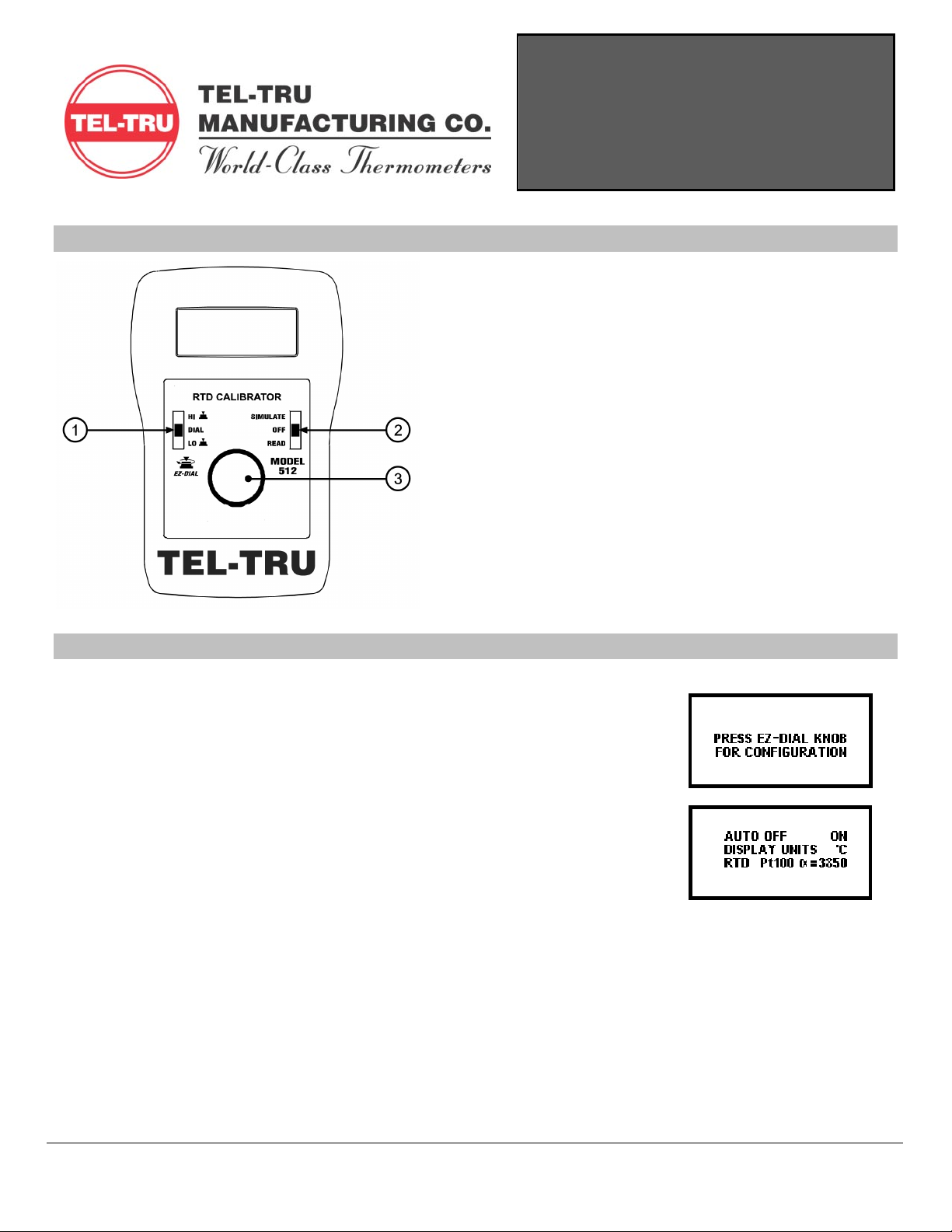
Basic Keypad Operations
1
11
1
EZ-Check™ Switch
Slide the switch to select from three user stored
values for the desired calibration points. The
user can select HI, DIAL, and LO positions.
These values can easily be changed to suit the
calibration requirements.
2
22
2
SIMULATE/OFF/READ Switch
Turn the Model 512 on to SIMULATE to output a
resistance corresponding to temperature. Turn
the unit to READ to read RTD resistance directly
in temperature.
3
33
3
EZ-Dial™ Knob
Turn the knob to change temperature in 0.1º
increments. Push and turn for faster dialing.
Push without turning to store new EZ-Check
HI/LO points in SIMULATE mode, or to clear EZ-
Check HI/LO points in READ mode.
Model 512 Configuration
Instructions for Enabling and Disabling the Configuration Options
1. Turn the Model 512 on to SIMULATE or READ.
2. Press the EZ-Dial Knob while the “PRESS EZ-DIAL KNOB FOR CONFIGURATION”
message is displayed.
3. Select options by turning the EZ-Dial Knob until the arrow points to the desired
option.
4. The option can be enabled or disabled by tapping the EZ-Dial Knob.
The Model 512 configuration menu will exit automatically after 5 seconds of inactivity and go
to normal operation with the options selected. These options are recalled at turn on until they
are changed again.
Model 512 Configuration Menu
AutoOff ON/OFF
If Auto Off is ON, the unit will turn off after 30 minutes to save battery life, if there is no user activity. If Auto Off is OFF the unit will
stay on until it is turned off from the keypad. This is typically useful for manual loading or continuous use.
Display Units °C/°F
Pressing the EZ-Dial Knob to toggles between °C or °F
RTD Pt100/Pt1000Ω=3850, Pt100 Ω=3902, Pt100 Ω=3916, Pt100 Ω=3926,
Cu10 Ω=427, Ni110 ΩBristol=5801, Ni120 Ω=672
To change RTD type, press the EZ-Dial Knob. Turn the EZ-Dial Knob to scroll through the list of available types. Press again to save
and return to the configuration menu.

Model 512 Operating Instructions
408 St. Paul Street, Rochester, NY 14605 Tel: 585.232.1440 • Fax: 585.232.3857 info@teltru.com • www.teltru.com
Tel-Tru Manufacturing Co. Copyright 2004. All rights reserved. 512INS904 11/22/04 2-6
Read Mode
Slide the SIMULATE/OFF/READ switch to READ for direct RTD input. The Model 512 displays temperature corresponding to resistance
input for the selected RTD type.
Automatic 2, 3, or 4 wire detect: Connect 2, 3, or 4 wires to the RTD sensor. Follow the connection diagrams. The Model 512
indicates “2W”, “3W”, or “4W” in the lower left corner of the display. Use this feature for troubleshooting broken leads or sensors.
Slide the EZ-Check Switch to HI and LO to recall maximum and minimum saved readings. Press and hold the EZ-Dial Knob to clear
saved readings. The display flashes “CLEARED” as a confirmation.
Be sure the switch is in the DIAL position to monitor input. Observe the “HI” and “LO” switch position indicators in the display.
Double-click the EZ-Dial Knob to return to the configuration menu.
Turning the EZ-Dial Knob has no effect in read mode.
Display Indications:
OVERRANGE or UNDERRANGE The resistance input exceeds the range of the selected RTD type.
OPEN RTD No RTD is connected.
MISCONNECT The Model 512 is incorrectly connected for a 3-wire reading. Both black leads are required.
Source Mode
Slide the SIMULATE/OFF/READ switch to SIMULATE for direct RTD output. The Model 512 outputs resistance corresponding to
temperature for the selected RTD type.
Turn the EZ-Dial Knob to change temperature, push and turn for faster dialing.
Slide the EZ-Check Switch to HI or LO to recall stored settings. While in the HI or LO position, dial a new setting and press the EZ-
Dial Knob to store. The DIAL position always holds the last setting dialed there.
Double-click the EZ-Dial Knob to return to the configuration menu.
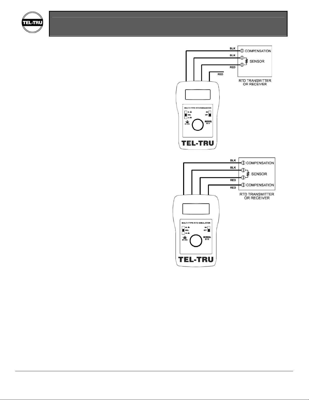
Connection Diagrams
Two Wire Connection to Transmitter
Model 512 Operating Instructions
408 St. Paul Street, Rochester, NY 14605 Tel: 585.232.1440 • Fax: 585.232.3857 info@teltru.com • www.teltru.com
Tel-Tru Manufacturing Co. Copyright 2004. All rights reserved. 512INS904 11/22/04 3-6
Three Wire Connection to Transmitter
Four Wire Connection to Transmitter

Model 512 Operating Instructions
408 St. Paul Street, Rochester, NY 14605 Tel: 585.232.1440 • Fax: 585.232.3857 info@teltru.com • www.teltru.com
Tel-Tru Manufacturing Co. Copyright 2004. All rights reserved. 512INS904 11/22/04 4-6
Specifications
General Specifications:
(Unless otherwise indicated all specifications are rated from a nominal 23°C, 70% RH for 1 year from calibration)
Temperature Range -25 to 60°C (-10 to 140°F)
Relative Humidity Range 10% ≤RH ≤90% (0 to 35°C), Non-condensing
10% ≤RH≤70% (35 to 60°C), Non-condensing
Size 4.9 X 3.15 X 1.82 inches (125.5 X 80 X 46.2 mm)
Weight 9.1 oz (258 grams)
Battery 9V Alkaline provides 45 hours of continuous use
Miscellaneous Low battery indication with nominal 1 hour of operation left
Protection to 60V for up to 30 seconds in duration
High contrast graphic liquid crystal display with 0.357” (9.07 mm) high digits
Resolution °C or °F / 0.01 Ω
Span 0.00-410.00 Ω
Accuracy ±(0.015% of Ω+ 0.05) Ω(see accuracy tables for temperature error)
Temperature Coefficient ±0.01% of span in Ω/°C ambient
RTD Simulation Specifications:
Allowable Excitation Current 100 µA to 10.2 mA, steady or pulsed/intermittent/smart
for accuracies below 100µA add ±10 µV/Excitation Current (units are in Ω)
Pulsed Excitation Current Compatibility DC to 0.01 second pulse widths
RTD Read Specifications:
Excitation Current 1.0 mA nominal
Available Options:
Carrying Case Part Number: 020-0201

Model 512 Operating Instructions
408 St. Paul Street, Rochester, NY 14605 Tel: 585.232.1440 • Fax: 585.232.3857 info@teltru.com • www.teltru.com
Tel-Tru Manufacturing Co. Copyright 2004. All rights reserved. 512INS904 11/22/04 5-6
Temperature Accuracy
The following charts give worst-case temperature accuracy based on stated resistance accuracy of ±(0.015 % + 0.05) Ω.
Pt100 TCR=0.003902
-200 to 850 °C
0.1
0.2
0.3
0.4
-200 0 200 400 600 800
Temperature °C
Error °C
Pt100 TCR=0.003916
-200 to 850 °C
0.1
0.2
0.3
0.4
-200 0 200 400 600 800
Temperature °C
Error °C
Pt100 TCR=0.003926
-200 to 850 °C
0.1
0.2
0.3
0.4
-200 0 200 400 600 800
Temperature °C
Error °C
Cu10 TCR=0.00427
-200 to 260 °C
1.2
1.25
1.3
1.35
1.4
-200 -100 0 100 200 300
Temperature °C
Error °C
Ni110 TCR=0.00530
-100 to 300 °C
0.08
0.1
0.12
0.14
0.16
-100 0 100 200 300 400
Temperature °C
Error °C
Ni120 TCR=0.00672
-80 to 260 °C
0.07
0.08
0.09
0.1
-100 -50 0 50 100 150 200 250 300
Temperature °C
Error °C

Model 512 Operating Instructions
408 St. Paul Street, Rochester, NY 14605 Tel: 585.232.1440 • Fax: 585.232.3857 info@teltru.com • www.teltru.com
Tel-Tru Manufacturing Co. Copyright 2004. All rights reserved. 512INS904 11/22/04 6-6
EZ-Dial and EZ-Check are trademarks of Practical Instrument Electronics, Inc.
Warranty
Our equipment is guaranteed against defective material and workmanship (excluding batteries) for a period of three years from the
date of shipment. Claims under guarantee can be made by returning the equipment prepaid to our factory. The equipment will be
repaired, replaced or adjusted at our option. The liability of Tel-Tru Manufacturing Co. is restricted to that given under our
guarantee. No responsibility is accepted for damage, loss or other expense incurred through sale or use of our equipment. Under no
condition shall Tel-Tru Manufacturing Co. be liable for any special, incidental or consequential damage.
Table of contents
Other TEL-TRU Test Equipment manuals


