TEL-TRU Check-Set Series User manual

Tel-Tru®Check-Set®Series of Thermometer Calibrators
QUICK START GUIDE
STEP 1 STEP 2
STEP 3
STEP 4
STEP 5
Register your new Check-Set at
www.teltru.com/checksetwarranty.aspx
Insert the power
cord into a standard
grounded outlet and
turn the unit on.
After a brief warm up period your Check-Set is ready for use. The unit is ready when you see the green
light turn on. Insert your thermometer and allow it to stabilize.
You’re ready!
Verify or calibrate your thermometer per the
manufacturer’s instructions (see reverse).
SCAN ME
for quick registration
on our website!!!
STEP 6
Keep your original
packaging for
calibration returns
and warranty
service. Visit us at
www.teltru.com/
calibrator.asp
for an extended
user’s manual,
FAQ and
accessories for
your Check-Set.
FACTORY RECALIBRATION/
RECERTIFICATION SERVICE
Tel-Tru Manufacturing Co. oers annual
maintenance, inspection, cleaning, and
accuracy recertication of each Check-Set
thermometer calibrator. Recertication
automatically extends the product warranty
for one year. Visit us at www.teltru.com/
calibrator.asp or contact Tel-Tru Customer
Service at 800-232-5335 for details.
Registering your Check-Set:
• Ensures warranty coverage for one year.
• Provides valuable information on how to have
your Check-Set recalibrated every year and
extend your warranty.
• Oers suggestions on how to keep your
Check-Set running trouble free for years to
come.
Tel-Tru Manufacturing Company
408 St. Paul Street, Rochester, NY 14605
Phone: 800.232.5335 • 585.232.1440
Fax: 585.232.3857
www.teltru.com
Check-Set Accuracy ±0.2ºF(0.1°C)
Important Things To Know...
CALIBRATION VERIFICATION PROCEDURE:
1. Insert thermometer probe into the appropriate opening in the front panel of calibrator.
2. Allow thermometer to remain in the opening until temperature indicator pointer or digital readout stabilizes.
3. Compare thermometer reading to the "Set" point of the Check-Set calibrator.
4. Make any calibration adjustments to the thermometer per the manufacturer's calibration instructions.
CSQ15rev1
© 2016
Drawing A
(CS1-HOT)
4.0" Insulated Zone 4.0" Te mp. Control Zone
PROBE SENSING AREA
PROBE SENSING AREA
3.0" Insulated 3.0" Temp.
Zone Control Zone
Drawing B
(All other models)
Drawing A
(CS1-HOT)
4.0" Insulated Zone 4.0" Te mp. Control Zone
PROBE SENSING AREA
PROBE SENSING AREA
3.0" Insulated 3.0" Temp.
Zone Control Zone
Drawing B
(All other models)
PROBE IMMERSION REQUIREMENTS
For best results, the sensing area of the probe must be
inserted completely into the Temperature Control Zone.
The minimum immersion depth is dependent on the
thermometer type. Check the manufacturer’s user
manual of your thermometer for the correct immersion
length.
TEL-TRU THERMOMETER CALIBRATOR CARE AND USE INSTRUCTIONS
Your Tel-Tru Thermometer Calibrator has been designed to provide many years of trouble-free service. You can help
ensure that your calibrator will provide you with this trouble-free service through careful use and basic maintenance
tasks. Set-up of all Tel-Tru Thermometer Calibrators should be done on a at, clean, dry surface, in a well ventilated
area. Set-up of the “cold” and “multi-temperature” Tel-Tru Thermometer Calibrators should be done in a manner that
provides maximum air circulation around the unit.
• Ideal ambient operating temperature should range
between 65°F and 85°F.
• Avoid setting the unit on surfaces that may restrict
air ow, such as carpet and towels.
• Allow clearance around the unit. It is better if the
unit is not “stacked” with other equipment.
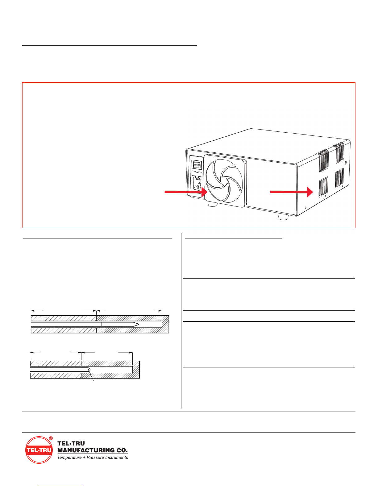
• The fan vent at the rear, and the exhaust vent
on the side of the unit must be kept clear.
• The air lter for the fan vent should be cleaned
regularly (DO NOT remove lter screws, the lter
guard can be “popped out” with your ngers).
• The tilt stand may be used to improve air circulation.
“READY-TO-USE” TIMES
Users often keep the Check-Set units on all day so they are
ready for use “on demand.” Typical ready-to-use times from
ambient:
Model Calibration
Temperature
Ready to
Use Time
Stability
Check-Set I HOT 140°F 10 min. ±0.06°F
160°F 14 min. ±0.06°F
212°F 20 min. ±0.06°F
Check-Set I COLD 40°F 5 min. ±0.03°F
Check-Set II 40°F 5 min. ±0.03°F
160°F 7 min. ±0.03°F
5°C 5 min. ±0.02°C
90°C 12 min. ±0.02°C
Check-Set IV 40°F 6 min. ±0.03°F
150°F 6 min. ±0.03°F
161°F 7 min. ±0.03°F
175°F 9 min. ±0.03°F
Table of contents
Other TEL-TRU Test Equipment manuals


Popular Test Equipment manuals by other brands


Tektronix
Tektronix TDS 540 user manual

Sealey
Sealey TA131 quick start guide

Jarvis
Jarvis AST-100 Series Installation, operation and maintenance instructions

HoldPeak
HoldPeak HP-6688BR Operation manual

Agilent Technologies
Agilent Technologies 54810A User's quick start guide

Velleman
Velleman Personal Scope HPS5 manual