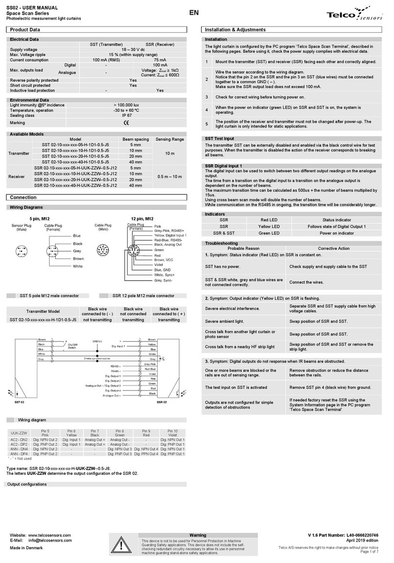
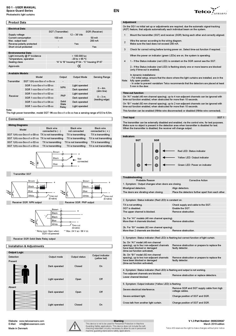
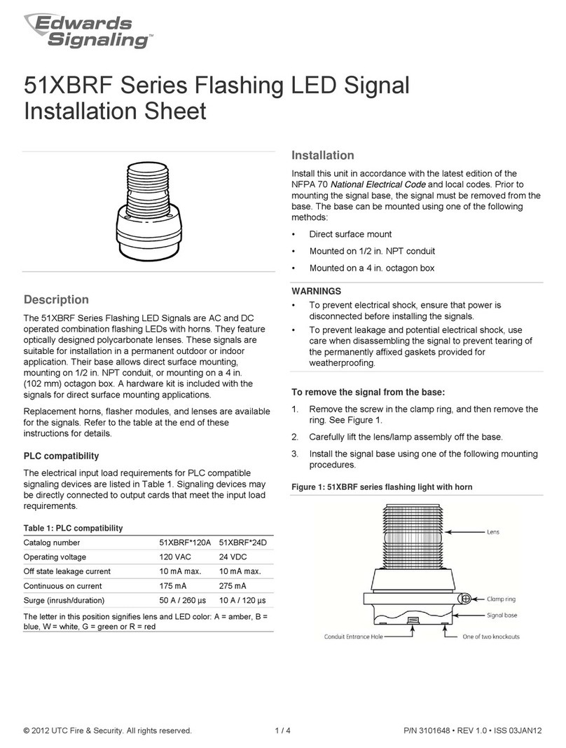
Telco Sensors Space Guard Series User manual

SG 15 – USER MANUAL
Space Guard Series
Photoelectric light curtains for automatic doors
Website: www.telcosensors.com
V 1.6Partnumber 0666220730
E-Mail: info@telcosensors.com
March 2019 edition
Made in Denmark
Telco A/S reserves the right to make changes without prior notice
tel
EN
Important Information
General
THIS LIGHT CURTAIN SG15 SHOULD ONLY BE INSTALLED BY AUTHORIZED AND FULLY
TRAINED PERSONNEL!
THE LIGHT CURTAIN IS ONLY A SAFETY PROTECTION DEVICE IF ALL INSTRUCTIONS
IN THIS MANUAL, ARE CAREFULLY FOLLOWED AND FULLY COMPLIED WITH. IN
ADDITION, THE INSTALLER IS REQUIRED TO COMPLY WITH ALL LOCAL LAWS AND
STANDARDS.
ANY ALTERATIONS TO THE DEVICE BY THE BUYER, INSTALLER OR USER MAY
RESULT IN UNSAFE OPERATING CONDITIONS.
Compliance to Directives and Standards
This device complies with the European directive 2006/42/EC for machinery and with the
European directive 2004/108/EC for electromagnetic compatibility, when used in accordance
with the instructions in this manual.
The compliance to the directive of machinery is declared according to EN 12978, with
normative reference to:
EN 13849-1, category 2, PL d
IEC 61496-2, type 2 ESPE
EC type examination:
TUV NORD CERT GmbH, Langemarckstr. 20, 45141 Essen (NB 0044)
EC-type certificate No. 44 205 13 413372-001
Product Data
Technical Data
SGT (Transmitter)
SGR (Receiver)
Supply voltage
12-30 Vdc
Max. Voltage ripple
15% (within supply range)
Reverse polarity protected
Yes
Max. current consumption
70 mA (RMS)
30 mA
Max. output load
-
100 mA
Max. output ON resistance
-
20Ω~ 2V@100mA
Max. leakage current
-
80uA
Short circuit protected
-
Yes
Inductive load protection
-
Yes
Output type
-
Opto coupled solid state relay
Sensing range
1 m - 12 m
Response time (max.)
50 ms
Environmental Data
Light immunity @ 5º incidence
> 100.000 lux
Temperature, operation
-20 to + 65 ºC
Temperature, storage
-40 to + 80 ºC
Sealing class
IP67
Marking
Output Mode
Models
Output Mode
SGR 15-xxx-0xx-x1-x-x9-xx
NC
Connection
Wiring Diagrams
Transmitter SGT 15
Receiver SGR 15 with solid state
relay used as NPN output
Receiver SGR 15 with solid state relay
used as PNP output
Receiver SGR 15 with solid state relay output.
Installation & Adjustments
General Instructions and Precautions
This light curtain can be used in industrial, commercial and garage doors and gates, as
described in EN 12453, when it is used as device type E according to clause 5.5.1. The light
curtain is intended to be mounted in the door plane of vertically sliding doors. It is important
that the lowest part of the door leaf will efficiently obstruct the light beams over a height of 50
mm.
Even though the light curtain has a high degree of immunity to ambient light sources, it is
recommended to avoid direct exposure to sunlight, and interference from flashlights or other
infrared light sources, such as other photo sensors.
If the front cover of the light curtain becomes contaminated, they have to be cleaned with a
slightly damp cloth. Do not use organic solvents or detergents. If the light curtain is very
contaminated, the output may go into safe state and de-energize even after the cleaning, due
to safety reasons. The light curtain will automatically make the necessary internal adjustments,
and within less than a few minutes, the light curtain will be fully adjusted and resume normal
operation. Immediate adjustment can be forced by switching the light curtain off and then on
again.
Ensure that the light curtain is mounted, so that it is mechanically stable during operation.
The light curtain must not be placed on moving doors.
Severe rain and snow may be detected due to the high sensitivity of the light curtain.
Indicators
Installation and Adjustment
No initial set up or adjustments are required, due to the automatic signal-tracking (AST)
feature, which automatically adjust each individual channel on the system.
1
Use the brackets supplied with the light curtain (at least 2 pcs, with max distance of
135 cm) to mount the transmitter (SGT) and receiver (SGR) facing each other and
correctly aligned.
2
Correct alignment is achieved when the front cover of the light curtains are parallel
and when a virtual line connecting top of the transmitter and receiver are
perpendicular to both transmitter and receiver front cover. (Within 2 deg.)
3 The light curtain has to stand on the pin in the bottom, in order to ensure that the
protective field is correctly positioned and in compliance with EN 12445
4 Wire the sensor according to the wiring diagram.
Make sure the load does not exceed 100 mA.
5 Check for correct wiring.
6 Turn power on.
7 The status indicator (red LED) on the SGR will flash quickly when the AST is active.
8 When the power on indicators (green LEDs) is on, the system is operating.
9 Notice that the rails must not be moved after the power to the SGR is turned on.
Safety Test - SGT/R Test Input
The function of the light curtain has to be tested before any door closing cycle (EN 12978
2009, 4.4.3), by activating the test input of the transmitter and the receiver. The SGR and the
SGT test input wires must be connected together. The test is enabled and disabled via the
black (SGT) and white (SGR) control wire. (See “Wiring Diagrams” and table below).
Activation of the test input will initiate an extensive internal safety test in both the transmitter
and the receiver. A faulty receiver or a faulty transmitter will turn on red led and go into safe
mode; the transmitter will stop transmitting and the receiver will de-energise the output until
test is repeated again with success.
An external controller ensures that the receiver de-energizes the output when the test inputs
are activated and that the receiver energizes the output when the test inputs are de-activated
again.
The test input on SGT/R has to be activated a certain minimum time Trin order to ensure that
the test request is registered and a test sequence is initiated.
On activation of the SGT/R test input, the output of the receiver will switch within a certain
maximum time TON .
When the test input of SGT/R is deactivated the output will be switched back within a certain
maximum time TOFF.
By only activating the test input on the SGT, a switch in output of the SGR should be observed.
If only the SGR test input is activated, no change in its output should be observed.
There must be at least 500ms from the start of one test pulse to the start of the next test pulse.
Note:Refer to “SGT/R Test Input Response Time “.
Red LED: Status indicator
SGT SGR
Yellow LED: Output indicator
Green LED: Power on indicator

SG 15 – USER MANUAL
Space Guard Series
Photoelectric light curtains for automatic doors
Website: www.telcosensors.com
V 1.6Partnumber 0666220730
E-Mail: info@telcosensors.com
March 2019 edition
Made in Denmark
Telco A/S reserves the right to make changes without prior notice
tel
EN
How the test inputs are to be operated depends on digit 0X on transmitter (SGT) and X9 on
receiver (SGR) in the model code;
SGT 15-xxx-0xx-x1-x-0X-xx
SGR 15-xxx-0xx-x1-x-X9-xx
Make sure no object is present in the detection area when test is done.
Model
Test input
connected to
0V - GND
Test input not
connected
Test input
connected to
+ supply
Transmitter
SGT
Receiver
SGR
00 09 Testing activated No testing No testing
03 39 No testing No testing Testing activated
04 49 Testing activated Testing activated No testing
SGT/R Test Input Response Time
Ton (max./min.) Toff (max./min.) Tr (min.)
120 ms / 9 ms 120 ms / 5 ms 200 ms
SGT test input response time graph
Output Logic
Detection Output mode Output status Output indicator
(yellow led)
Present
Light operated
(N.C.) Open Off
Absent
Light operated
(N.C.)
Closed On
Housing Length, Number of Channels and Door closing speed
Housing Length, Number of Channels and Door closing speed
Housing
length
Beam
Placement
Active Height
Number of
channels
Maximum door
closing speed
1948 mm
C1
1800 mm
40
1,2 m/s
D1
1800 mm
28
1,7 m/s
E1
1800 mm
16
1,9 m/s
2308 mm
C1
2160 mm
48
1,0 m/s
D1
2160 mm
30
1,6 m/s
E1
2160 mm
18
1,9 m/s
2668 mm
C1
2520 mm
56
0,9 m/s
D1
2520 mm
32
1,5 m/s
E1
2520 mm
20
1,9 m/s
Dynamic Blanking Function
Dynamic Blanking Function
All the infrared light beams can be blanked out (made inactive) without changing state of the
output of the receiver by moving a non-transparent object, as the door leaf, between the SGR
and SGT from top of the rails (wire end) and downwards to the lowest beam.
In order for the blanking process to function correctly, it is recommended that the blanking
object has a minimum vertical height of 50 mm and enough width to ensure that the front
window of the light curtain is fully covered during the closing process. Beams are blanked in
(activated) when the door motion is reversed.
The light curtain supports partial opening of the door, for energy saving or ventilation.
However, notice that the stop either has to be in the zone with 45 mm beam spacing or then
the bottom part of the door leaf has to obstruct the beams over 200 mm, keeping the lowest
beam obstructed when stopped. This limitation exists for safety reasons; the light curtain shall
not respond with permanent blanking of beams for objects just passing through the beams and
thereafter taken out of the active zone. Notice also that the door has to be outside the
detection zone when the safety test is done.
All beams will stay blanked, as long as the lowest beam, at the bottom of the rails is
obstructed. Make sure that the lowest beam is kept well obstructed, when door has finished
closing. The blanked beams are ignored by the output logic.
Maximum door closing speed See table other place on this page.
There is no restriction on maximum speed when the door is opening.
When a blanking object of 50 mm vertical height is passing areas with 180 mm beam spacing
the minimum speed of the blanking object is 0.18 m/s. If the blanking object has a size so at
least one beam is always obstructed there are no minimum blanking speed.
If the door leaf is stopped in the bottom of the rails just above the second lowest beam the door
cannot proceed downwards to the lowest beam after some time without de-energizing the
output. This is done for security reasons. To proceed downwards the door must in this case
first be reversed to above the third lowest beam.
If the door leaf is stopped between the rails before the bottom (lowest) IR beam is reached and
3 or more IR beams above the door edge are not obstructed, the output will switch to a safe
state after 2 seconds for SG15 C1 systems and 4 seconds for SG15 D1 and E1 systems.
Notice that the actual speed of the bottom door edge can fluctuate for a non-rigid door construction
and it is advised that the door speed therefore has to be set lower than listed in the table other place
on this page, in order not to exceed the maximum speed limit of the light curtain while the door is
closing.
Be aware that side to side movements of a round bottom door edge will also contribute to the
fluctuation of the obstruction speed. It is therefore best to have a horizontal straight edge for
obstruction of the light beams.
Troubleshooting
Troubleshooting
Probable Reason Corrective Action
1. Symptom: Red LED on SGT/R is constant on. All other LEDs are off.
Error found during test process Check supply and cable to the SGT/R.
Or replace the rail(s).
2. Symptom: Red and green LEDs on SGT is constant on.
Error found during test process Replace the SGT rail.
3. Symptom: Red and green LEDs on SGR is constant on.
Error found during test process Replace the SGR rail.
4. Symptom: Yellow LED on SGR is flashing
Cross talk from another light curtain, or
other powerful light sources. Change position of the SGT and SGR rails.
5. Symptom: Yellow LED on SGR is constant off. Red LED is off.
Rails are out of sensing range Check the sensing range and power to the SGT.
6. Symptom: After start up, red LED on SGR continues to flash quickly. Green LED is on.
Rails are out of sensing range or
SGT is not turned ON or an object is
obstructing one or more beams.
Check the sensing range and for objects
between the SGT and the SGR.
Check SGT is powered or replace rails.
7. Symptom: After start up, green LED on SGT/R is on. Yellow LED on SGR is off.
Test input is constant activated under and
after start up. Deactivate the test input on SGT/R.
Disposal
Disposal
The light curtain should only be replaced if a similar protection device is installed. Disposal
should be done using the most up-to-date recycling technology according to local rules and
laws.
Manufacturer
Manufacturer
Telco A/S, Nørregade 10 C, 4600 Køge, Denmark
Lars Krarup, Managing Director
This manual suits for next models
1
Other Telco Sensors Lighting Equipment manuals
Popular Lighting Equipment manuals by other brands
Sonoff
Sonoff LBS B02-F user manual

Laserworld
Laserworld Club Series Speed Edition manual
Bardic
Bardic Fast LG1LF Installation - Maintenance Testing Instructions and Warranty
Piscines Magiline
Piscines Magiline FX30 installation manual
LED Group
LED Group ROBUS SPENCER RSN0640-24 quick start guide
X4-Life
X4-Life 701593 instruction manual
