Hytronik SensorDIM HEC9025 User manual

Subject to change without notice. Edition: 26 Feb. 2020 Ver. A0 Page 1/7
0s ~ 1h, +∞(selectable)
Easy-on-the-eye operation which makes the light turning on/off less uncomfortable
DIP switch offers multiple current selections for different luminaire requirements
Tri-level dimming control based upon occupancy (also known as corridor function)
TM
5-Year Warranty
Input current
Input power
0.15
31W (Max.)
20s
Warming-up
10% / 20% / 30% / 50%
Stand-by period
Stand-by dimming level
Sensor OFF / 50% / 75% / 100%
Daylight threshold
Hold time
Sensitivity
Setting adjustments:
5s ~ 30min (selectable)
2 ~ 50 lux, disabled
HEC9025 HEC9025/I
Detached Version with Tri-level Control / Photocell AdvanceTM
SensorDIMTM - Integrated HF Sensor and LED Driver
Applications
Occupancy sensor and constant current LED driver, 2-in-1.
Suitable for building into the xture for:
Ofce / Commercial Lighting
Classroom
Meeting Room
Use for retrot and new luminaire designs/installations
Features
IP20RED
EMC standard (EMC)
Safety standard (LVD)
Abnormal protection
Certication
Dielectric strength
Output short-circuit protection
Semko, CB, CE , EMC, RED, RCM
Input→output: 3750VAC / 5mA /1min
Technical Data
Input Characteristics
Safety and EMC
Off load voltage
Power factor
Efciency
Output current 350/500/550/700/750/900mA
55V
85% (Max.)
Driver Data
Tc: +80
O
C
Operation temperature
Case temperature (Max.)
Ta: -20
O
C~ +50
O
C
Environment
IP20
IP rating
Sensor Data
Model No.
30O~ 150O
<0.2mW
5.8GHz +/- 75MHz
High Frequency (microwave)
Sensor principle
Operation frequency
Transmission power
Detection range
Detection angle
Max. ( Ox H) 12m x 6m
Model No.
220~240VAC 50/60Hz
Mains voltage
HEC9025 HEC9025/I HEC9025 HEC9025/I
>0.9
Special photocell to measure and differentiate natural light from LED light from behind the xture cover (HEC9025/I)
Photocell Advance
EN55015, EN61547, EN6100-2/3
EN61347-1, EN61347-2-13
, SELV

Subject to change without notice. Edition: 26 Feb. 2020 Ver. A0 Page 2/7
Model SAM4
Use with HEC9025,
optional cable entry
(side entry and back
entry)
With the detached sensor antenna, it requires very little space on the LED panel. Only the antenna is installed on the PCB surface, while
the main body can be hidden behind the panel. Completely shadow free.
Model SAM5/I
Use with HEC9025/I,
with photocell advanceTM
function.
Main Body
LED current
selection
LED
-
LED + N
L
Antenna module
connector
Detection area
Hold-time
Stand-by dimming level
Stand-by period
Daylight threshold
26
104
53
4.2
110.7
119.5
Number of Drivers Based upon 16A Circuit Breaker
Loading and In-rush Current
Model
In-rush Current (Imax.)
Pulse Time
HEC9025
48A
40μs
HEC9025/I
48A
40μs
Conversion table for max. quantities of drivers on other types of Miniature Circuit Breaker
manufactures datasheet for loading and derating factors.
B
B
B
B
B
16A
10A
13A
20A
25A
100% (see table above)
63%
81%
125%
156%
C
C
C
C
C
10A
13A
16A
20A
25A
104%
135%
170%
208%
260%
MCB TypeRatingRelative number of driversMCB Type RatingRelative number of drivers
HEC9025
42
HEC9025/I
42
Cct Breaker Type
Type B
25
2.5
11.2
6.8
8.8
34.7
35.9
40.4
2.5
25.2
6.6
φ4.5
25
1.5
24.3
15.5
13
φ4
Drill hole 9mm x 3mm
Drill hole for cable entry is 10mm x 10mm in
square shape or φ12mm in round shape
25.2
2.5
30.7
35.9
40.4
1.5
12
20.8
25
2.5
11.2
6.8
8.8
φ4
25
φ3.5
Drill hole 9mm x 3mm
Drill hole for cable entry is 10mm x 10mm in
square shape or φ12mm in round shape

Subject to change without notice. Edition: 26 Feb. 2020 Ver. A0 Page 3/7
6
0
6
Detection Pattern
2 in 1 and cost effective! This is a smart integration of microwave motion sensor and multiple current selection LED driver, which gives
pre-selected constant current to drive the LEDs to work based upon movement detection.
Hold-time
5s~30min 2~50Lux
Functions and Features
Photocell AdvanceTM Function (for HEC9025/I)
1
It’s well known that LED lights have a totally different spectrum to natural light. Hytronik uses this principle and comes up with special
photocell and sophisticated software algorithm to measure and differentiate natural light from LED light from behind the xture cover,
so that this photocell can ignore internal LED light and only respond to the natural light outside.
Our technology has no infringement to the existing patents in the market.
Tri-level Control (Corridor Function)
2
Hytronik builds this function inside the motion sensor to achieve tri-level control, for some areas which require a light change notice
before switch-off. The sensor offers 3 levels of light: 100%-->dimmed light -->off; and 2 periods of selectable waiting time: motion
hold-time and stand-by period; Selectable daylight threshold and freedom of detection area.
With sufcient natural light, the
light does not switch on when
presence is detected.
With insufcient natural light,
the sensor switches on the light
automatically when presence is
detected.
After hold-time, the light dims to
stand-by level preset.
Light switches off automatically
after the stand-by period
elapses.
Photocell Advance
TM
2
8:30
With insufcient natural light, the light
switches on at 100% when there is
motion detected.
1
18:00
The light automatically turns on at dim
level when natural light lux level drops
below pre-set daylight threshold.
Settings on this demonstration:
Hold-time: 10min Daylight threshold: 50lux Stand-by dimming level: 10% Stand-by period: +∞
The light turns off completely whenever
natural light reaches above pre-set
daylight threshold, even with presence.
3
11:30
Note:We recommend the mounting distance between sensor to sensor should be more than 2m to prevent sensors from
false-triggering.

Subject to change without notice. Edition: 26 Feb. 2020 Ver. A0 Page 4/7
Detection Pattern
Wall mounted height (m)
Ceiling mounted detection pattern (m) Wall mounted detection pattern (m)
Ceiling mounted height(m)
6
9
0
6
4
0
10%
10%
30%
30%
75%
75%
50%
50%
Settings (Remote Control HRC-11, for HEC9025/I)
Press button “RESET”, all settings go back to DIP switch settings.
Reset Settings
Permanent ON/OFF function
Press button “ON/OFF” to select permanent ON or permanent OFF mode.
* Press button “AUTO”, “RESET” or “Ambient” to quit this mode.
The mode will change to AUTO Mode after power failure.
AUTO mode
Press button “AUTO” to initiate automatic mode. The sensor starts working and all
settings remain as before the light is switched ON/OFF.
Note: the function of SEMI-AUTO is disabled.
ON/
OFF
Press button “Shift”, the LED on the top left corner is on to indicate mode selection.
All values / settings in RED are valid for 20 seconds.
Shift Button
Press the buttons to select light output at 80% (at initial 10,000 hours) or 100%.
Power output
1. Press button “Shift”, the red LED is on for indication.
2. Press button “Sensor off”, the function of movement detection and daylight sensor
both are disabled.
Sensor off function
1. Press button “Shift”, the red LED is on for indication.
2. Press button “Twilight”, the function of movement detection is disabled. This unit is
now a LED driver plus daylight sensor with daylight harvest function.
Twilight mode
Press the buttons under below modes:
AUTO mode: to adjust hold-time light brightness.
Sensor off mode: to adjust light brightness.
Twilight mode: to adjust light brightness and reset the output lux value in line with natural light for daylight harvest function. The
higher natural lux level, the lower output brightness, and vice-versa.
Brightness +/-
&
A
4
4 hhh
HRC-11
Load Indication:
The light will ash ONCE rapidly after
receiving the commamd from the
remote control successfully.

Subject to change without notice. Edition: 26 Feb. 2020 Ver. A0 Page 5/7
1Detection Range
Sensor sensitivity can be adjusted by selecting the combination on the DIP
switches to t precisely for each specic application.
DIP Switch Settings
Note: by choosing “Sensor OFF”, it becomes an ordinary driver without
both occupancy detection and daylight sensor.
I – 100%
II – 75%
III – 50%
IV – Sensor OFF
100%
75%
50%
Sensor OFF
1 2
1. Press button “Shift”, the red LED is on for indication.
2. Press button “Ambient”, the surrounding lux level is sampled and set as the new daylight threshold.
Ambient daylight threshold
Press buttons in zone “ Daylight threshold” to set daylight sensor at 2Lux/ 10Lux / 50Lux / 100Lux / 300Lux / 500Lux / Disable.
Note: To set daylight sensor at 100Lux / 300Lux / 500Lux, press “Shift” button rst.
Detection range
Daylight threshold
Scene program - 1-key commissioning
1. Press button “Start” to program.
2. Select the buttons in “Detection range”, “Daylight threshold”, “Hold-time”, “Stand-by time”, “Stand-by dimming level” to set all
parameters.
3. Press button “Memory” to save all the settings programmed in the remote control.
4. Press button “Apply” to set the settings to each sensor unit(s).
For example, to set detection range 100%, daylight threshold Disable, hold-time 5min, stand-by time +∞, stand-by dimming level 30%, the steps should be:
Press button “Start”, button ”100%”, “Disable”, “Shift”, “5min”, “Shift”, “+∞”, “30%”, “Memory”. By pointing to the sensor unit(s) and pressing “Apply”, all
settings are passed on the sensor(s).
Press buttons in zone “Detection range” to set detection range at 100% / 75% / 50% / 10%.
1. Press button “Shift”, the red LED starts to ash.
2. Press button “Ambient”, the surrounding lux level is sampled and set as the new daylight threshold.
Ambient daylight threshold
Hold-time
Stand-by dimming level
Stand-by time (corridor function)
Press buttons in zone “hold-time” to set the hold-time at 2s / 30s / 1min / 5min / 10min / 15min / 20min / 30min.
Note: 1. To set hold-time at 30s / 5min / 15min / 30min, press “Shift” button rst.
2. 2s is for testing purpose only, stand-by period and daylight sensor settings are disabled in this mode.
*To exit from Test mode, press button “RESET” or any button in “Hold-time”.
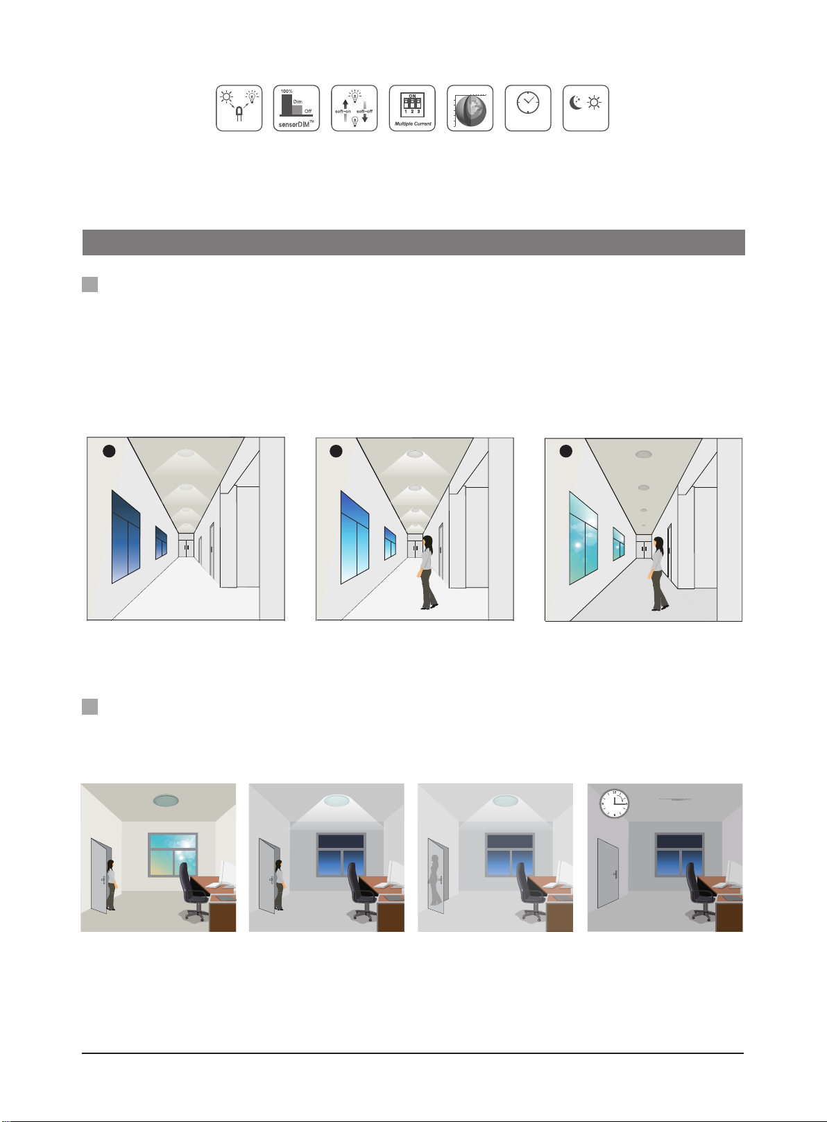
Press buttons in zone “stand-by time” to set the stand-by period at 0s / 10s / 1min / 5min / 10min / 30min / 1h / +∞.
Note: “0s” means on/off control; “+∞” means the stand-by time is innite and the light is effectively controlled by the daylight sensor, off when natural light is
sufcient and automatically on at dimming level when insufcient.
Press the button in zone “stand-by dimming level” to set the stand-by dimming level at 10% / 20% / 30% / 50%.
Dual tech & RF mode
Auto-conguration function
All buttons in this zone are disabled.

Subject to change without notice. Edition: 26 Feb. 2020 Ver. A0 Page 6/7
Current
350mA
500mA
550mA
700mA
750mA
900mA
1 2 3
3.5~15W (350mA) 5~21W (500mA) 5.5~22W (550mA)
7~25W (700mA) 7~25W (750mA) 9~25W (900mA)
10~43V (350mA) 10~42V (500mA) 10~40V (550mA)
10~36V (700mA) 10~34V (750mA) 10~28V (900mA)
This multiple current LED driver has a wide range of loading capacity:
Maximum load @ different currents:
Maximum voltage @ different currents:
LED Driver Specication
LED Current Selections
1
The current can be easily congured by
choosing the correct combination of the
DIP switches (see table on the left).
LED Maximum Load and Voltage
2
2Hold Time
4Stand-by period (corridor function)
Select the DIP switch conguration for the light on-time after presence detection.
This function is disabled when natural light is sufcient.
This is the time period you would like to keep at the low light output level
before it is completely switched off in the long absence of people.
3Daylight Threshold
Set the level according to the xture and environment. The light will not turn on if
ambient lux level exceeds the daylight threshold preset.
Please note that the ambient lux level refers to internal light reaching the sensor.
Disabling the daylight sensor will put the sensor into occupancy detection only mode.
I – Disable
II – 50Lux
III – 10Lux
IV – 2Lux
21
50Lux
10Lux
2Lux
Disable
I
II
III
IV
I – 5s
II – 30s
III – 1min
IV – 5min
V – 10min
VI – 20min
VII – 30min
3
21
30min
5s
30s
1min
5min
10min
20min
I
II
III
IV
V
VI
VII
0s
10s
1min
5min
10min
30min
1H
∞
+
2 31
I – 0s
II – 10s
III – 1min
IV – 5min
V – 10min
VI – 30min
VII – 1H
VIII – ∞
+
5Stand-by dimming level
The setting is used to select the desired dimmed light level used in
periods of absence for enhanced comfort and safety. 30%
20%
10%
50%
21
I
II
III
IV
I – 10%
II – 20%
III – 30%
IV – 50%
Note: “0s” means on/off control; “+∞”means the stand-by period is innite and
the light never switches off but stays at dimming level (HEC9025);
For HEC9025/I, “+∞”means the stand-by period is innite and the light is
effectively controlled by the daylight sensor, off when natural light is
sufcient and automatically on at dimming level when insufcient.

Subject to change without notice. Edition: 26 Feb. 2020 Ver. A0 Page 7/7
Additional Information / Documents
1. For full explanation of Hytronik Photocell AdvanceTM technology, please kindly refer to
www.hytronik.com/download ->knowledge ->Introduction of Photocell Advance
2. Regarding precautions for microwave sensor installation and operation, please kindly refer to
www.hytronik.com/download ->knowledge ->Microwave Sensors - Precautions for Product Installation and Operation
3. Regarding Hytronik standard guarantee policy, please refer to
www.hytronik.com/download ->knowledge ->Hytronik Standard Guarantee Policy
This manual suits for next models
1
Table of contents
Other Hytronik Lighting Equipment manuals
Popular Lighting Equipment manuals by other brands

S&P
S&P PCRL80 manual

Laserworld
Laserworld LED-36MH user manual

Photon Systems Instruments
Photon Systems Instruments SL 3500 Instruction guide

Lectranator Systems
Lectranator Systems DIG60 Installation and operation manual

Bosch
Bosch MIC7000 Quick installation guide

Somogyi
Somogyi home KD 90 T quick start guide

CSL
CSL Eco-Downlight EDL-NC quick start guide

Beghelli
Beghelli Sicura Unit instructions

EuroLite
EuroLite EL Wire 2m user manual

Public Safety Equipment
Public Safety Equipment Code 3 DuoBeam II DB2-2LMCNFPA1 Installation & operation manual

DTS
DTS DELTA 12 HEAD user manual

Heitronic
Heitronic 27794 Installation and operating instructions