Telco Sensors Space Guard Series User manual

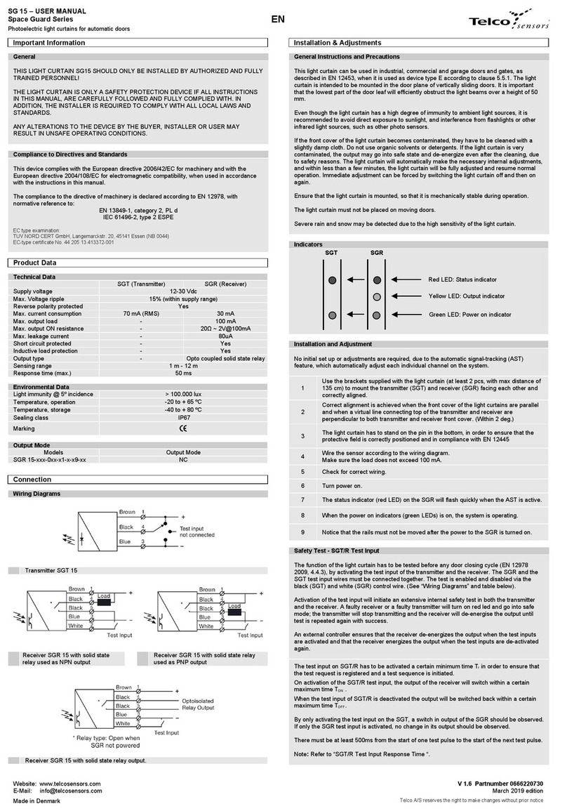
SG 1 - USER MANUAL
Space Guard Series
Photoelectric light curtains
Website: www.telcosensors.com
Warning
V 1.3 Part Number: 0666220647
E-Mail: info@telcosensors.com
This device is not to be used for Personnel Protection in Machine
Guarding Safety applications. This device does not include the self-
checking redundant circuitry necessary to allow its use in personnel
machine guarding stand-alone safety applications.
March 2019 edition
Made in Denmark
Telco A/S reserves the right to make changes without prior notice
tel
EN
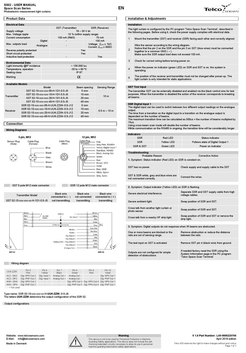
Product Data
Electrical Data
SGT (Transmitter)
SGR (Receiver)
Supply voltage
12 – 36 Vdc
Current consumption
100 mA
50 mA
Max. output load
-
200 mA
Reverse polarity protected
Yes
Short circuit protected
-
Yes
Environmental Data
Light immunity @ 5º incidence
> 100.000 lux
Temperature, operation
-20 to + 65 ºC
Sealing class
“A” & “B” housing IP 54 - “C” housing IP 67
Approvals
Available Models
Model Output Output Mode Sensing Range
Transmitter SGT 1(H)-xxx-0xx-x1-x-0x-xx - -
0 – 4m.
(slim line)
0 – 3 m.
(leading edge)
Receiver
SGR 1-xxx-0xx-x1-x-00-xx NPN Light operated
SGR 1-xxx-0xx-x1-x-01-xx Dark operated
SGR 1-xxx-0xx-x1-x-02-xx
PNP
Light operated
SGR 1-xxx-0xx-x1-x-03-xx Dark operated
SGR 1-xxx-0xx-x1-x-04-xx
Solid
State
Relay
Dark operated
SGR 1-xxx-0xx-x1-x-05-xx Light operated
Note:
The high power transmitter, model SGT 1H-xxx-0xx-x1-x-0x-xx has a sensing range of 0,5 to 6,5m.
Connection
Wiring Diagrams
Model
Black wire
connected to ( - )
Black wire
not connected
Black wire
connected to ( + )
SGT 1(H)-xxx-0xx-x1-x-00-xx
TX is not transmitting
TX is transmitting
TX is transmitting
SGT 1(H)-xxx-0xx-x1-x-01-xx
TX is not transmitting
TX is transmitting
TX is not transmitting
SGT 1(H)-xxx-0xx-x1-x-02-xx
TX is transmitting
TX is not transmitting
TX is transmitting
SGT 1(H)-xxx-0xx-x1-x-03-xx
TX is transmitting
TX is transmitting
TX is not transmitting
Transmitter SGT
Receiver SGR NPN output
Receiver SGR PNP output
Receiver SGR Solid State Relay output
Installation & Adjustments
Output Logic
Detection Output mode Output status
Output indicator
(yellow led)
Present
Dark operated Closed On
Light operated Open Off
Absent
Dark operated Open Off
Light operated Closed On
Adjustment
On the SG1 no initial set up or adjustments are required, due the automatic signal-tracking
(AST) feature, that adjusts automatically each individual beam on the system.
1 Mount the transmitter (SGT) and receiver (SGR) facing each other and correctly aligned.
2 Wire the sensor according to the wiring diagram.
Make sure the load does not exceed 200 mA.
3 Check for correct wiring before turning power on. Select time-out function if required.
4
When the power on indicator (green LEDs) are on, the system is operating.
1.- If the Status indicator (red LED) is constant on the SGR cannot see the SGT.
2.- If the Status indicator (red LED) is flashing slowly one or more beams are blocked
(only if time-out is enabled).
Note:
In dynamic installations:
- For initial setup, ensure that the doors where the light curtains are installed, are in the
fully open position.
- In order to prevent vandalism Telco recommends that the detectors are placed at least
5 mm in the door.
Time-out function
On “A1” model (46 mm channel spacing), up to 4 non-adjacent channels can be ignored with
time-out function enabled, when obstructed for more than 10 seconds.
On “B1” model (92 mm channel spacing), up to 2 non-adjacent channels can be ignored with
time-out function enabled, when obstructed for more than 10 seconds.
This function can be enabled (White wire disconnected) or disabled (White wire connected).
Test Input SGT 1
The transmitter can be externally disabled and enabled, via the control wire, for test purposes.
Make sure no object is present in the detection area when transmitter is disabled for test.
When the transmitter is disabled, the receiver will change output.
Indicators
Troubleshooting
Probable Reason
Corrective Action
1. Symptom: Output changes when doors are closing.
Misaligned detectors.
Align detectors.
The doors are vibrating when closing. Place the detectors further apart from each other.
2. Symptom: Status indicator (Red LED) is constant on.
TX is not emitting.
Check supply and cable to the SGT.
SGT is disabled.
Enable the SGT.
The upper channel is blocked.
Remove obstruction.
2a. For “A1” models (46 mm channel spacing).
More than 4 channels blocked.
Remove obstruction.
2b. For “B1” models (92 mm channel spacing).
More than 2 channels are blocked.
Remove obstruction.
3. Symptom: Status indicator (Red LED) is flashing but correct function of light curtain.
3a. On “A1” model (46 mm channel
spacing), up to four non-adjacent channels
have been blocked or damaged
(time-out function activated).
Remove obstruction or prepare to replace the
faulty detector.
3b. On “B1” model (92 mm channel
spacing), up to two non-adjacent channels
have been blocked or damaged
(time-out function activated).
Remove obstruction or prepare to replace the
faulty detector.
4. Symptom: Status indicator (Red LED) is flashing and output is not working.
Two adjacent channels are blocked.
Remove obstruction or replace detectors.
Lower channel blocked
5. Symptom: Output indicator (Yellow LED) is flashing
Severe electrical interference. Remove SGR and SGT supply cable from high
voltage cables.
Severe ambient light. Change position of SGT and SGR.
Cross talk from another light curtain. Change position of SGT and SGR.
Red LED: Status indicator
SGT SGR
Yellow LED: Output indicator
Green LED: Power on indicator
!

SG 1 - USER MANUAL
Space Guard Series
Photoelectric light curtains
Website: www.telcosensors.com
Warning
V 1.3 Part Number: 0666220647
E-Mail: info@telcosensors.com
This device is not to be used for Personnel Protection in Machine
Guarding Safety applications. This device does not include the self-
checking redundant circuitry necessary to allow its use in personnel
machine guarding stand-alone safety applications.
March 2019 edition
Made in Denmark
Telco A/S reserves the right to make changes without prior notice
tel
Dimensions and Descriptions
Slim Line “A“ Housing – IP 54
Leading Edge “B” Housing – IP 54
SGT/SGR
Side View
SGT/SGR
Side View
SG 1 085/125/160
SGT/SGR
Side View
SGT/SGR
Side View
SG 1 200
SGR
Rear View
SGT
Rear View
!

SG 1 - USER MANUAL
Space Guard Series
Photoelectric light curtains
Website: www.telcosensors.com
Warning
V 1.3 Part Number: 0666220647
E-Mail: info@telcosensors.com
This device is not to be used for Personnel Protection in Machine
Guarding Safety applications. This device does not include the self-
checking redundant circuitry necessary to allow its use in personnel
machine guarding stand-alone safety applications.
March 2019 edition
Made in Denmark
Telco A/S reserves the right to make changes without prior notice
tel
Dimensions and Descriptions
Slim Line “C” Housing – IP 67
Recommendations for elevator installations Fig. 1
Fasten the cables with cable clips.
In dynamic applications, please make sure
that the cables can move freely
In order to prevent vandalism Telco recommends that the detectors are placed at least 5 mm in the door.
Position of Channels & Channel spacing
46 mm channel spacing
(Drawing of 2000 mm housing length, 40 channels model)
Housing Length & Number of Channels
92 mm channel spacing
(Drawing of 2000 mm housing length, 20 channels mode)
Fig. 2
Housing
Length Active height Number of
Channels
Channel
Spacing
Fig. 3
850 mm
669 mm 8 92 mm
715 mm 16 46 mm
1250 mm
1037 mm 12 92 mm
1083 mm 24 46 mm
1600 mm
1405 mm 16 92 mm
1451 mm 32 46 mm
2000 mm
1773 mm 20 92 mm
1819 mm 40 46 mm
To determine the position of channels on each different model,
use this table and refer to fig. 2 & 3. Channel nº 1 at the bottom.
Um die Position der Kanäle auf jedem der unterschiedlichen
Modelle festzustellen, benutzen Sie diese Tabelle und beziehen
Sie sich auf Bild 2 u.3.
Kanal Nº1 befindet sich unten.
Pour déterminer la position des canaux sur chaque modèle
différent, utilisez cette table est référez-vous à fig. 2 et 3.
Canal n° 1 au fond.
Para determinar la posición de los canales en cada modelo,
utilice esta tabla y véase fig. 2 y 3.
El canal nº 1 está situado en la parte inferior.
Min 10 mm.
Min 10 mm.
!
This manual suits for next models
5
Other Telco Sensors Lighting Equipment manuals
