SGB0416BX SGB0400AX
2
3
2
ENGLISH
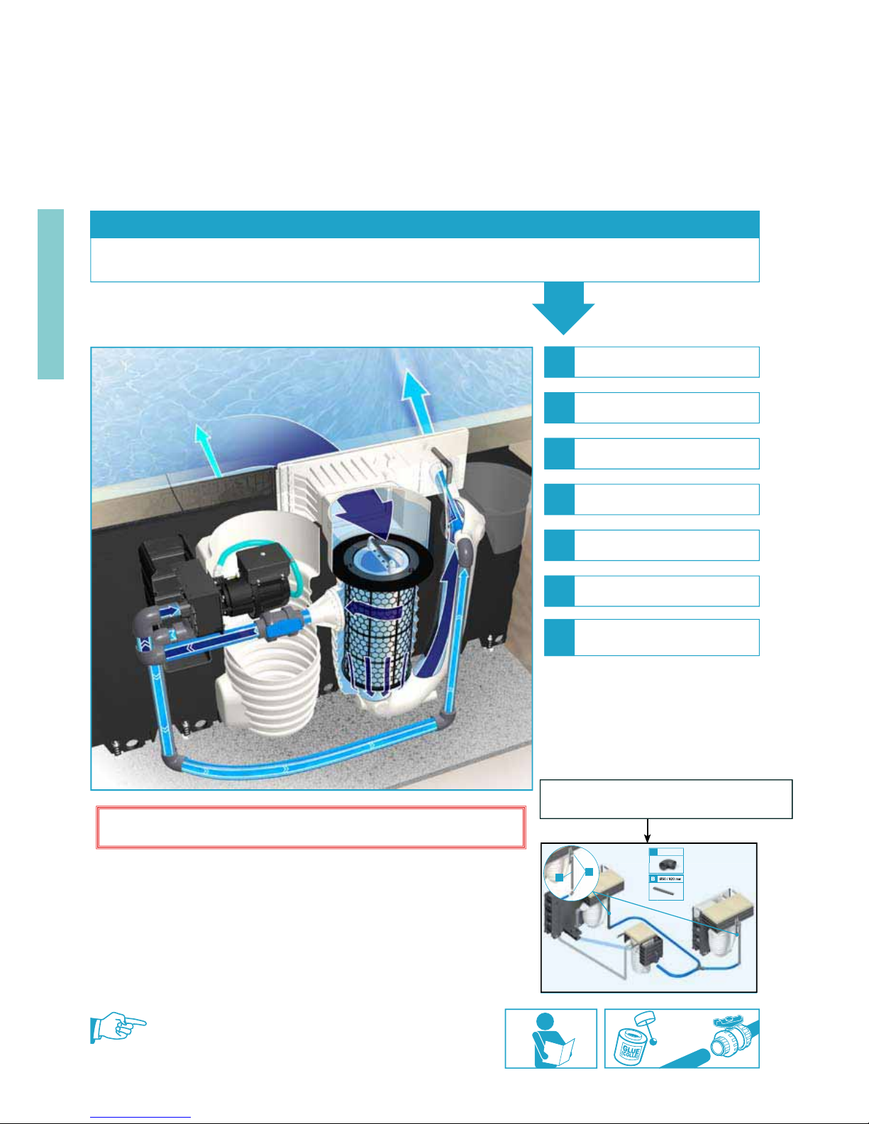
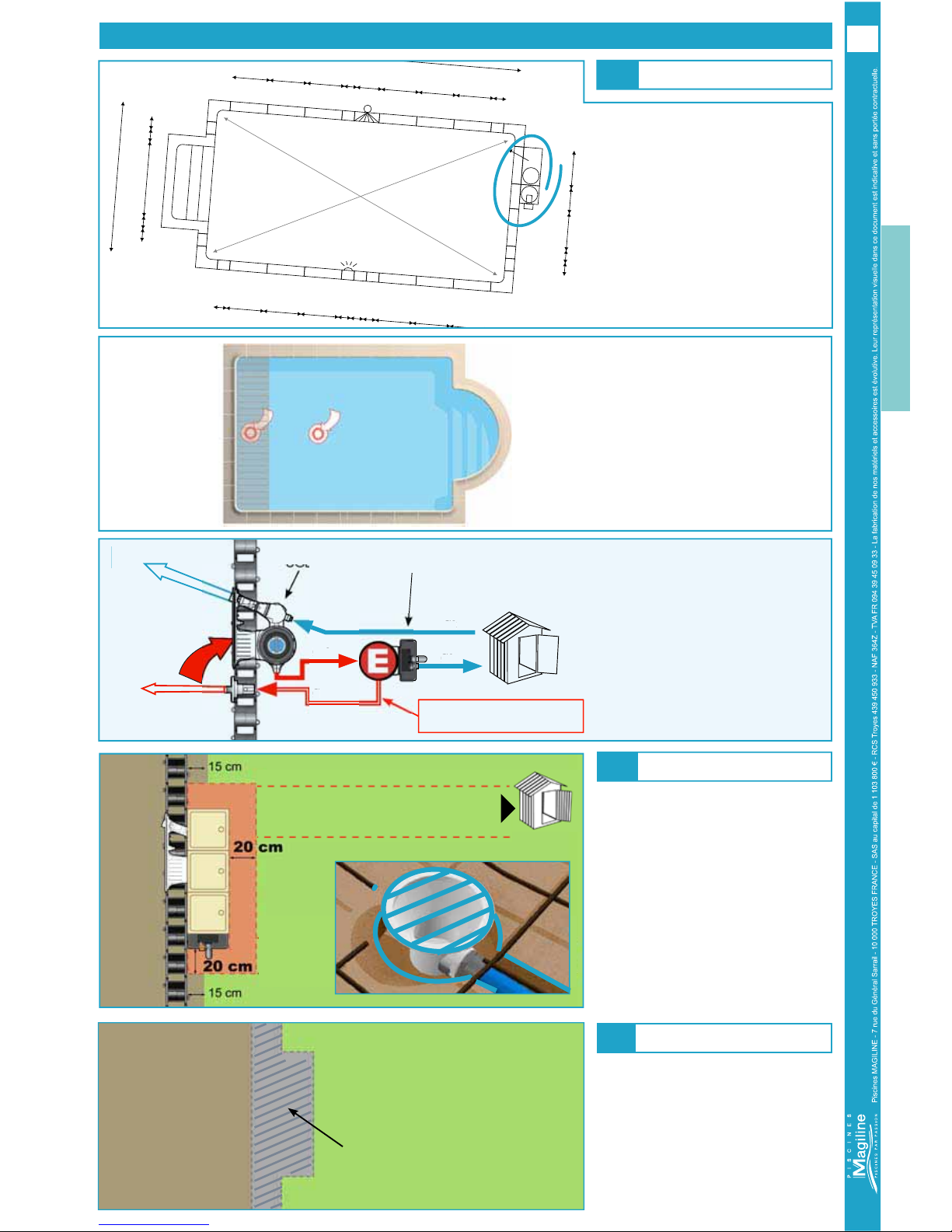
Positioning
EARTHWORKS
A) Classic FX 30 :
)RUWKHSRVLWLRQLQJRIWKH¿OWHULWLV
imperative to refer to the drawing.Any
PRGL¿FDWLRQZLOOYRLGWKHZDUUDQW\RID
JRRGIXQFWLRQLQJRIWKH¿OWUDWLRQH[FHSW
in case of validation by our technical
service).
B) FX 30 with Additional discharge / FX
30 with shutter Box :
Use the drawing to correctly position
hte Additional Discharge Module.
C) FX 30 with Main Drain :
The main drain(s) are preferably
located in the deepest part of the pool
or in the shutter box.
D) FX 30 with separation of the electric
pump :
The electric pump must be placed
between the swimming pool and the
equipment room, at a distance of
not more than 10 m (for the booster
function).
The electric pump is designed to
operate with a positive discharge
pressure, and so must be below the
level of the water in the swimming pool.
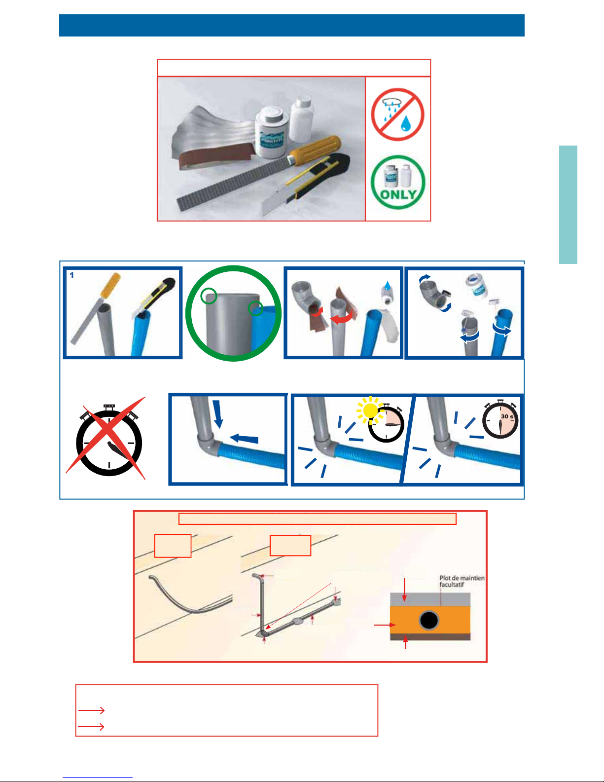
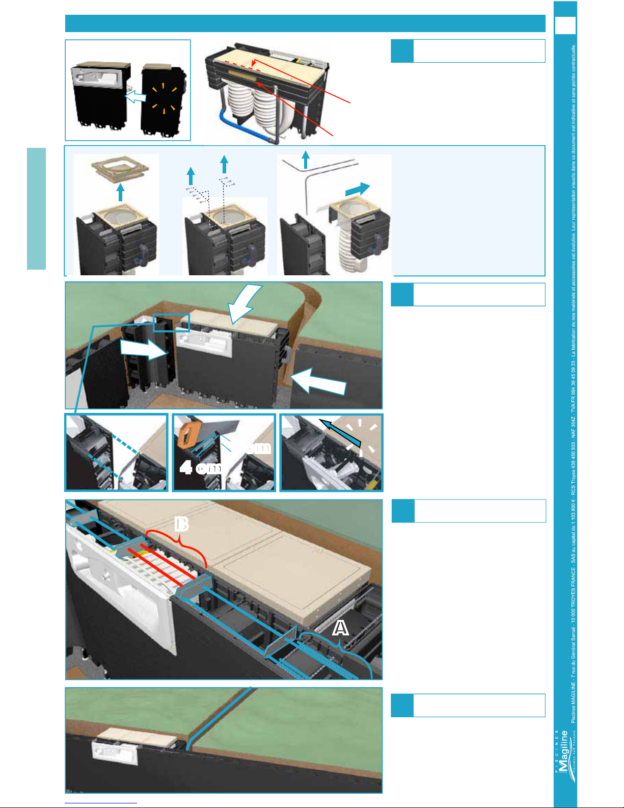
Concrete base
Earthworks
The base of the structure must extend to
the whole clear space.
A) To facilitate making the connections,
leave a 20 cm clear space on both sides
of the module(s).
B) FX 30 with Main Drain :
Protect the drain by adhesive tape.
Concrete base
Trench to Automatic
Equipments room
5HIHUWRWKHJHQHUDOPDQXDO
5,*,'39&',$PP
QRWPRUHWKDQP
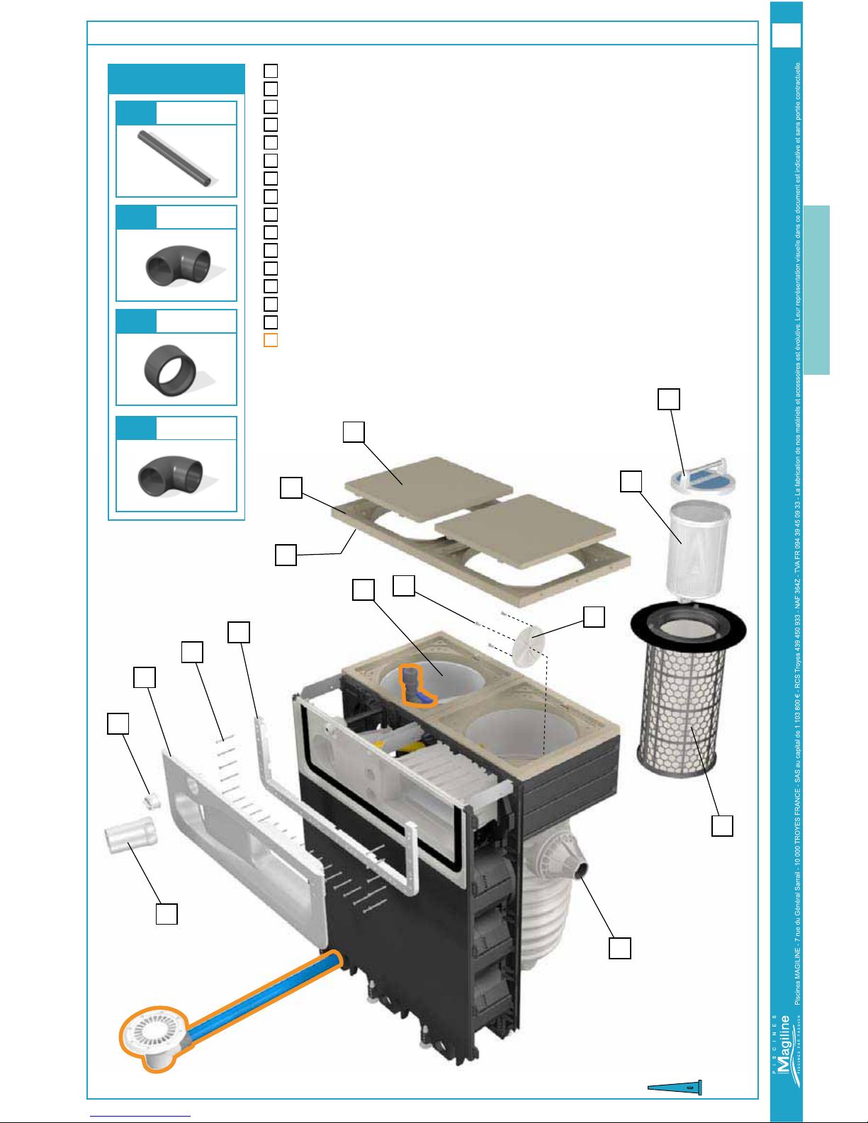
FX Line FX30
7/16
TERRASSEMENT - EARTHWORK - GRONDWERKEN
ERDARBEITEN - SCAVO - EXCAVACIÓN