Telco Systems AC-211 User manual

MN100129 Rev A01
ACCESS 211 VoIP
GATEWAY
(AC-211)
USER GUIDE

ACCESS 211 VOIP GATEWAY (AC-211) USER GUIDE
MN100129 Rev A01
2
Revision History
Revision Date Description
A01 April 01, 2004 1. Adapted for UL/FCC
2. Section 10.4 formerly for H.323 and SIP is now
separated – now Section 10.4 for SIP with revised rules
for Hold call, Call waiting, Transfer call, and Conference
(flash without following digits), and Section 10.5 for
H.323 with contents as before.

ACCESS 211 VOIP GATEWAY (AC-211) USER GUIDE
MN100129 Rev A01
3
Table of Contents
INTRODUCTION ..................................................................................................................................4
TO REACH US VIA THE WEB....................................................................................................................4
TO REACH US BY E-MAIL........................................................................................................................4
TO CALL US BY PHONE ...........................................................................................................................4
PRODUCT OVERVIEW....................................................................................................................... 5
THE FRONT PANEL .................................................................................................................................. 5
THE REAR PANEL....................................................................................................................................6
INSTALLATION ...................................................................................................................................7
BEFORE YOU BEGIN ................................................................................................................................7
THE FOLLOWING EQUIPMENT IS REQUIRED .............................................................................................7
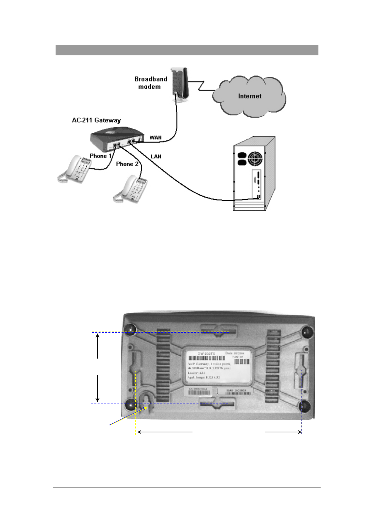
TO INSTALL YOUR ACCESS 211 VOIP GATEWAY WITH A SINGLE PC: .................................................... 8
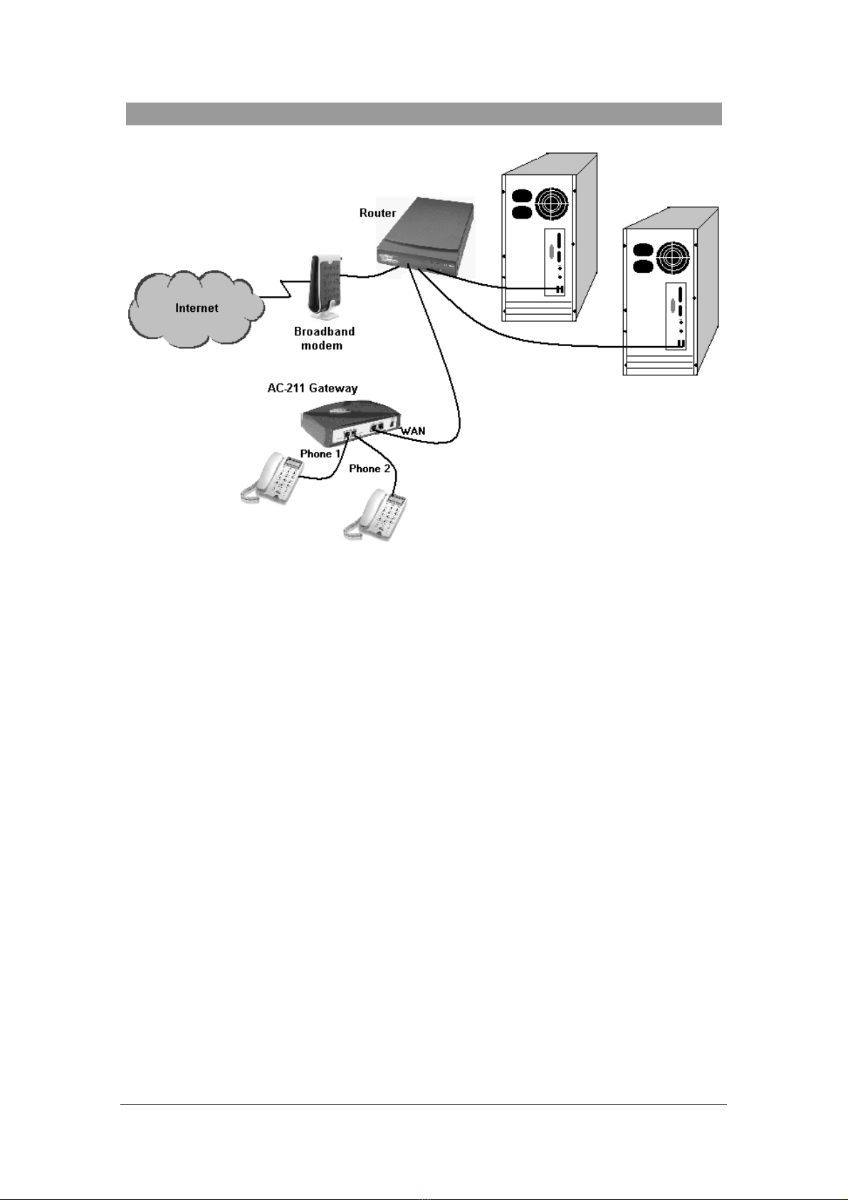
TO INSTALL YOUR ACCESS 211 VOIP GATEWAY WITH A HOME NETWORK: .........................................10
ADVANCED CONFIGURATION VIA THE WEB.......................................................................... 12
WAN CONFIGURATION........................................................................................................................12
ENABLING POINT-TO-POINT PROTOCOL OVER ETHERNET (PPPOE).....................................................15
MAC SPOOFING ...................................................................................................................................16
LAN CONFIGURATION ......................................................................................................................... 16
Configuring LAN Settings ................................................................................................................17
DHCP Server Configuration............................................................................................................18
Port Forwarding ..............................................................................................................................20
COMPLETING THE ACCESS 211 GATEWAY CONFIGURATION................................................................ 21
USING THE ACCESS 211 GATEWAY ............................................................................................23
FIRST CALL ..........................................................................................................................................23
ADVANCED CALLING FEATURES FOR SIP............................................................................................. 23
Call Waiting .....................................................................................................................................23
Conference Call ...............................................................................................................................23
Forward a call ................................................................................................................................. 23
Transfer call.....................................................................................................................................23
Hold..................................................................................................................................................24
ADVANCED CALLING FEATURES FOR H.323.........................................................................................24
Call Waiting .....................................................................................................................................24
Conference Call ...............................................................................................................................24
Forward a call ................................................................................................................................. 24
Transfer call.....................................................................................................................................25
Hold..................................................................................................................................................25
ADVANCED CALLING FEATURES FOR MGCP....................................................................................... 25
TROUBLESHOOTING.......................................................................................................................26
SPECIFICATIONS ..............................................................................................................................27

ACCESS 211 VOIP GATEWAY (AC-211) USER GUIDE
MN100129 Rev A01
4
Introduction
Thank you for purchasing this product. We at Telco Systems are confident that you will obtain full
satisfaction from your new Access 211 VoIP gateway. Please read this guide carefully in order to
make use of all the advanced features provided by the Access 211. Should you encounter any
difficulties, do not hesitate to contact us by E-mail, phone, or via our Web site. Telco Systems
technical support team will ensure that the prompt and easy access that our customers have come to
expect for their Telco Systems' products will be maintained.
This guide is intended for users connecting to the Internet or Intranet with VoIP service set up by a
provider and the access-211 gateway factory pre-configured. If this is not the case, refer also to the
administrator's manual.
T
T
To
o
o
r
r
re
e
ea
a
ac
c
ch
h
h
u
u
us
s
s
v
v
vi
i
ia
a
a
t
t
th
h
he
e
e
W
W
We
e
eb
b
b
http://www.telco.com
T
T
To
o
o
r
r
re
e
ea
a
ac
c
ch
h
h
u
u
us
s
s
b
b
by
y
y
E
E
E-
-
-m
m
ma
a
ai
i
il
l
l
support@batm.co.il
T
T
To
o
o
c
c
ca
a
al
l
ll
l
l
u
u
us
s
s
b
b
by
y
y
p
p
ph
h
ho
o
on
n
ne
e
e
Telco systems Tech Support Hotline
800-227-0937 (U.S. and Canada)

ACCESS 211 VOIP GATEWAY (AC-211) USER GUIDE
MN100129 Rev A01
5
Product Overview
The Access-211 is a terminal Voice-over-IP (VoIP) WAN gateway device with two VoIP ports,
which can be used to connect one or two independent analog telephone or Fax lines over the
Internet or Intranet.
The Access-211 supports all standard analog DTMF telephones and accessories, including:
•Single-line touch-tone telephones.
•Multiple-line touch-tone telephones.
•Touch-tone telephones with redial or speed-dial features.
•Phones or accessories that support Caller ID.
•Answering machines with touch-tone support.
•Phones or accessories that support Distinctive Ring.
NOTE Pulse-dial telephones and accessories are not supported.
T
T
Th
h
he
e
e
f
f
fr
r
ro
o
on
n
nt
t
t
p
p
pa
a
an
n
ne
e
el
l
l
The Access 211 Gateway’s front panel contains six LEDs:
•Two link LEDs indicate Link and Activity status for the WAN and LAN. Steady glow
indicates Link, and blinking indicates Activity.
↓
↑
Four status LEDs provide operating information explained in the following table.
Status LED Indicators
LED Mode H.323, MGCP, SIP Status Downloader Status
Power Steady glow Power OK Power OK
Ready Blinking Application OK Loader OK
Voice Steady glow Gateway registered with Gatekeeper
/ Call Agent / SIP Server
Mngt Blinking Management or voice activity Management activity

ACCESS 211 VOIP GATEWAY (AC-211) USER GUIDE
MN100129 Rev A01
6
T
T
Th
h
he
e
e
r
r
re
e
ea
a
ar
r
r
p
p
pa
a
an
n
ne
e
el
l
l
The rear panel contains the phone connectors, the LAN and WAN connectors and the input DC
power connector, as shown in the following figure. The optional Life Line socket on the left is
designed to provide a public network connection in the event of power failure.
CAUTION Never connect the Phone connectors to the public telephone outlet, or to
each other. Only the Life Line connector, if provided, may be connected to
the public telephone outlet.

ACCESS 211 VOIP GATEWAY (AC-211) USER GUIDE
MN100129 Rev A01
7
Installation
B
B
Be
e
ef
f
fo
o
or
r
re
e
e
y
y
yo
o
ou
u
u
b
b
be
e
eg
g
gi
i
in
n
n
Before you begin to install your Access 211 VoIP Gateway, make sure that the temperature and
humidity of the operating environment are always kept within the following range limits:
Ambient temperature 0°C - 45°C (32°F - 113°C)
Humidity 10% - 90% non-condensing
T
T
Th
h
he
e
e
f
f
fo
o
ol
l
ll
l
lo
o
ow
w
wi
i
in
n
ng
g
g
e
e
eq
q
qu
u
ui
i
ip
p
pm
m
me
e
en
n
nt
t
t
i
i
is
s
s
r
r
re
e
eq
q
qu
u
ui
i
ir
r
re
e
ed
d
d
to set up and use your Access 211 VoIP Gateway:
•Optionally, a PC or a laptop computer with a LAN card, a web browser and Telnet.
•An Ethernet cable (supplied) for the Ethernet connection from the Access 211
Gateway to your router or modem.
•An Ethernet cable (not supplied) to connect the unit to your computer devices.
•Two push-button telephones with DTMF (tone signal) capability (not supplied).
•An AC/5VDC power adapter (supplied).
The AC-211 must be powered by an external UL listed limited power source
or Class II power source (AC/DC adapter), rated input: 100 -250 V, 47-63Hz,
0.2A, output: 5VDC – 2A.
The unit is not intended for connection to the Telecommunication Network.
Only indoor copper connections are permitted for this unit.

ACCESS 211 VOIP GATEWAY (AC-211) USER GUIDE
MN100129 Rev A01
8
T
T
To
o
o
i
i
in
n
ns
s
st
t
ta
a
al
l
ll
l
l
y
y
yo
o
ou
u
ur
r
r
A
A
Ac
c
cc
c
ce
e
es
s
ss
s
s
2
2
21
1
11
1
1
V
V
Vo
o
oI
I
IP
P
P
G
G
Ga
a
at
t
te
e
ew
w
wa
a
ay
y
y
w
w
wi
i
it
t
th
h
h
a
a
a
s
s
si
i
in
n
ng
g
gl
l
le
e
e
P
P
PC
C
C:
:
:
1. Unpack the Access 211 Gateway unit.
2. Choose a location that is near the devices to be connected and close to an electrical outlet.
Place the unit on a desktop or other level surface. You may also mount the unit on the wall,
using two wood screws 6.1” (15.5 cm) apart for horizontal positioning or 2.68” (6.8 cm) apart
for vertical positioning. Use screws as specified in the table below. Holes for mounting on the
wall are situated at the bottom of the unit, as shown in the following figure.
Clasp for fastening DC
power-feed cable
Distance for horizontal
hanging = 6.1” ( 15.5 cm)
Distance for horizontal
hanging = 6.1” ( 15.5 cm)
Distance for vertical hanging
= 2.68” ( 6.8 cm)

ACCESS 211 VOIP GATEWAY (AC-211) USER GUIDE
MN100129 Rev A01
9
Mounting screws maximum dimensions
Head diameter (H): Max 9 mm (0.35")
Shank diameter (S): Max 3.5 mm (0.138")
Length (L): 25-30 mm (1"-1.2")
3. Optionally connect the LAN port on the AC-211 Gateway's rear panel to the network socket
on your PC with an Ethernet 10/100BaseTX (RJ-45) cable.
4. Connect the phones to the Phone1 and Phone2 ports on the Access 211 rear panel with RJ-11
Phone cables. Up to five phones in parallel may be connected to each port. (If your provider
enables only one phone line, use the Phone1 port).
5. Verify that all system components are properly installed. Make sure that all cable connectors
are securely positioned in the appropriate ports.
6. Connect the power adapter to the power connector of the unit and to the power source.
7. Check that the Power LED on the AC-211 front panel glows steadily.
8. Turn on your PC.
9. If you are using a DSL modem, you will need to enable PPPoE as described in the section
Enabling Point-to-Point Protocol over Ethernet (PPPoE) on page 15, and disable PPPoE on
your PC.
10. Wait for the Voice LED on the AC-211 front panel to glow, indicating connection to your
Internet and VoIP providers. It may take a minute or two for these connections to be
established.
11 Verify that your broadband Internet service functions properly. If the Internet service does not
work as it did before you installed the AC-211, refer to Troubleshooting on p. 26.
12. Pick up the phone on each line to verify that you can hear the dial tone. If no dial tone is heard,
refer to Troubleshooting on p. 26.
Once the installation is complete, you can use your Access 211 Gateway for telephone calls and for
the Internet.
S
H
L

ACCESS 211 VOIP GATEWAY (AC-211) USER GUIDE
MN100129 Rev A01
10
T
T
To
o
o
i
i
in
n
ns
s
st
t
ta
a
al
l
ll
l
l
y
y
yo
o
ou
u
ur
r
r
A
A
Ac
c
cc
c
ce
e
es
s
ss
s
s
2
2
21
1
11
1
1
V
V
Vo
o
oI
I
IP
P
P
G
G
Ga
a
at
t
te
e
ew
w
wa
a
ay
y
y
w
w
wi
i
it
t
th
h
h
a
a
a
h
h
ho
o
om
m
me
e
e
n
n
ne
e
et
t
tw
w
wo
o
or
r
rk
k
k:
:
:
1. Unpack the Access 211 Gateway unit.
Place the Access 211 Gateway on a desktop or other level surface, or mount it on a wall.
Choose a location that is near the devices to be connected and close to an electrical outlet.
2. Connect the WAN port on the AC-211 rear panel to an open Ethernet LAN port on your
router with a supplied Ethernet 10/100BaseTX (RJ-45) cable, in accordance with the
instructions provided with your router
3. Connect the phones to the Phone1 and Phone2 sockets on the Access 211 rear panel with RJ-
11 Phone cables. Up to five phones in parallel may be connected to each port. (If your
provider enables only one phone line, use the Phone1 port).
4. Turn on your broadband modem and your router, and follow the instructions provided with
these devices.
5. Verify that all system components are properly installed. Make sure that all cable connectors
are securely positioned in the appropriate ports.
6. Connect the power adapter to the power connector of the unit and to the power source.
7. Check that the Power LED on the AC-211 front panel glows steadily.
8. Turn on your PC. Verify that your broadband Internet service functions properly. If the
Internet service does not work as it did before you installed the AC-211, refer to
Troubleshooting on p. 26.

ACCESS 211 VOIP GATEWAY (AC-211) USER GUIDE
MN100129 Rev A01
11
9. Wait for the Voice LED on the AC-211 front panel to glow, indicating connection to your
Internet and VoIP providers. It may take a minute or two for these connections to be
established.
10. Pick up the phone on each line to verify that you can hear the dial tone. If no dial tone is heard,
refer to Troubleshooting on p. 26.
The Access 211 Gateway is now ready for performing telephone calls.

ACCESS 211 VOIP GATEWAY (AC-211) USER GUIDE
MN100129 Rev A01
12
Advanced Configuration via the Web
If you need to configure your Access-211 Gateway, proceed as follows.
•Connect a PC to the LAN port on the rear panel of the unit.
•Open your Web browser on the PC.
•In the Web browser's address field, type 192.168.100.1 (the default LAN IP address of
the Access 211 Gateway) to open the home page of the unit.
•To update a setting, proceed as described in the following sections. Enter the required
settings on the appropriate Web pages and then save the changes by clicking on the Save
button at the bottom of each page.
•Once all settings have been saved, select the Reset option on the left-hand side of the
Web page to reset the VoIP Gateway and effectuate the new settings.
W
W
WA
A
AN
N
N
C
C
Co
o
on
n
nf
f
fi
i
ig
g
gu
u
ur
r
ra
a
at
t
ti
i
io
o
on
n
n
To change the WAN mode from using the DHCP default configuration to fixed IP, or to
assign a different fixed IP address, configure the unit as follows:
1. Connect your PC to the Access 211 LAN connector.
2. Configure the PC to acquire an IP address dynamically (DHCP) or set it to a fixed IP
address in the subnet 192.168.100.xxx.
3. Enter the IP address of the Access 211 Gateway into the PC Web browser. The Access
VoIP Gateway home page appears (Figure 1).
Figure 1: Access VoIP Gateway Home Page

ACCESS 211 VOIP GATEWAY (AC-211) USER GUIDE
MN100129 Rev A01
13
4. In the vertical menu bar on the left, select WAN.
The WAN Status page appears:
Figure 2: WAN Status Page
5. To change network and VoIP IP settings, select WAN Settings on the horizontal menu bar.
The WAN Configuration page appears (Figure 3).

ACCESS 211 VOIP GATEWAY (AC-211) USER GUIDE
MN100129 Rev A01
14
Figure 3: WAN Configuration Page
6. Select either of the following options.
To obtain a WAN IP address dynamically:
•Select Obtain WAN configuration dynamically.
OR
To specify fixed values for the WAN IP address, mask, gateway, DNS Server, etc:
•Select Specify fixed WAN Configuration
•The following fields, associated with fixed IP addressing should be filled in or
changed only if your broadband provider requires them. Use the values supplied by
your broadband provider:
IP Address, IP Netmask, IP Gateway, IP DNS Server 1 and 2,Host Name and
Domain Name.
8. Multicast Limits – Limits for Multicast and broadcast traffic, as percentage of Ethernet bit-
rate traffic:

ACCESS 211 VOIP GATEWAY (AC-211) USER GUIDE
MN100129 Rev A01
15
•Broadcast limit
•Multicast limit
9. Scroll down to the bottom of the Web page, and click Save WAN Settings.
10. Select Reset in the vertical menu bar, to reset the unit (see Completing the Access 211
Gateway Configuration on page 21).
E
E
En
n
na
a
ab
b
bl
l
li
i
in
n
ng
g
g
P
P
Po
o
oi
i
in
n
nt
t
t-
-
-t
t
to
o
o-
-
-P
P
Po
o
oi
i
in
n
nt
t
t
P
P
Pr
r
ro
o
ot
t
to
o
oc
c
co
o
ol
l
l
o
o
ov
v
ve
e
er
r
r
E
E
Et
t
th
h
he
e
er
r
rn
n
ne
e
et
t
t
(
(
(P
P
PP
P
PP
P
Po
o
oE
E
E)
)
)
If you have a DSL modem and are NOT using a router between the AC-211 and the modem,
configure PPPoE as follows:
1. In the horizontal menu bar of the WAN page, select PPPoE.
The WAN PPPoE Configuration page appears (Figure 4).
Figure 4: WAN PPPoE Configuration Page
2. Select Yes in the Enable PPPoE drop-down list box.
3. Fill in the username and password in the Authentication fields as supplied by your DSL
provider. Optionally you can enter the service name for the requested service. To select a
specific provider, enter his access name in the AC name field. Click Save PPPoE Settings.
4. Select Reset in the vertical menu bar, to reset the unit (see Completing the Access 211
Gateway Configuration on page 21).

ACCESS 211 VOIP GATEWAY (AC-211) USER GUIDE
MN100129 Rev A01
16
M
M
MA
A
AC
C
C
S
S
Sp
p
po
o
oo
o
of
f
fi
i
in
n
ng
g
g
MAC spoofing may be required in the case that your broadband provider associates a particular
service to a specific device (e.g. your computer).
To override the AC-211's MAC address that you supplied to you broadband provider
1. In the horizontal menu bar of the WAN page, select MAC Spoofing.
The MAC Spoofing Configuration page appears (Figure 5).
Figure 5: MAC Spoofing Configuration Page
2. Enter the MAC address of your device and click Save MAC Spoofing Settings.
L
L
LA
A
AN
N
N
C
C
Co
o
on
n
nf
f
fi
i
ig
g
gu
u
ur
r
ra
a
at
t
ti
i
io
o
on
n
n
The LAN Configuration Web pages allow you to configure the following LAN settings:
•LAN IP address and subnet mask;
•LAN broadcast and multicast traffic limitation;
•Rate control;
•DHCP Server settings;
•Port forwarding – to enable access to local ports from an external network.
To open the LAN Configuration pages:
In the vertical menu bar on the left of the Access VoIP Gateway Web page, select LAN.
The LAN Configuration page appears (Figure 6).

ACCESS 211 VOIP GATEWAY (AC-211) USER GUIDE
MN100129 Rev A01
17
Figure 6: LAN Configuration Page
Configuring LAN Settings
To configure LAN settings, broadcast and multicast traffic limits and/or rate control, proceed
as follows:
1. In the LAN Configuration page, enter the LAN IP address and subnet mask.
2. Optionally, set the broadcast and multicast limits in the appropriate fields.
3. Select one of the following Rate Control options:
•Disable Rate Limits (this is the default setting)
OR
•Dynamic Rate Limits
OR
•Fixed Rate Limits
With the Rate control feature you can limit the bandwidth allocated to the device(s) connected
to the LAN port. This is especially important for broadband users where the upload link to the

ACCESS 211 VOIP GATEWAY (AC-211) USER GUIDE
MN100129 Rev A01
18
ISP is considerably lower than the download link from the ISP. Setting the Rate control
parameters will insure that even while running heavy bandwidth applications on the devices
connected to LAN port the voice quality is preserved.
Select Fixed Rate Limits to limit the bandwidth received from the LAN to the value of the
LAN Rate Limit that is specified in the textbox (in Kbps). If you change this value, the actual
rate limit will be rounded to the nearest multiple of 32 Kbps.
If you want to select the Dynamic Rate Limit option you must first set the User Upload Rate
parameter to the value of the user’s available upload bandwidth on the WAN connection. The
Access gateway will dynamically reserve bandwidth for the active calls and limit the
bandwidth for the LAN device to the remaining available bandwidth. By default the User
Upload Rate is set to 32 Kbps. If you change this value, the actual upload rate will be rounded
to the nearest multiple of 32 Kbps. You can view the actual bandwidth allocated to the LAN
device in the Current LAN Rate Limit parameter.
4 Click Save LAN Settings.
DHCP Server Configuration
To use DHCP Server for assigning IP addresses and subnet masks automatically to
devices connected to the LAN port, proceed as follows:
1. In the horizontal menu bar of the LAN page, select DHCP.
The DHCP Server Configuration page appears (Figure 7).
Figure 7: DHCP Server Configuration Page

ACCESS 211 VOIP GATEWAY (AC-211) USER GUIDE
MN100129 Rev A01
19
2. To enable the DHCP Server, select the Server Settings Enabled option.
3. Fill in the following fields:
•Client IP Address range – up to 10 IP addresses are allowed. To change the LAN
IP, see Configuring LAN Settings on page 17.
•Domain Name – optionally enter the domain name for the local LAN.
•DNS Server 1 and 2 – if left blank, the DNS Server IP addresses will be acquired
from the WAN connection. If you want to use different DNS Server addresses,
enter their IPs.
•You can define LAN devices statically. The devices can be defined by Host
name or by MAC address:
oIdentity Using – Select the type of identifier, Host name or MAC,
you wish to use in the next field.
oHost Identifier – Enter the appropriate value (Host name or MAC).
oInternal address – static IP of the local host.
4. To view the DHCP Client table (Figure 8), click on View DHCP Table.

ACCESS 211 VOIP GATEWAY (AC-211) USER GUIDE
MN100129 Rev A01
20
Figure 8: DHCP Client Table Page
Port Forwarding
Port forwarding associates local port ranges to local P addresses in order to enable external network
users to access local devices, without the need for the local servers to first access the global
network.
To configure port forwarding:
1. In the horizontal menu bar of the LAN page, select Port Forwarding.
The Port Forwarding Configuration page appears (Figure 9).
Table of contents