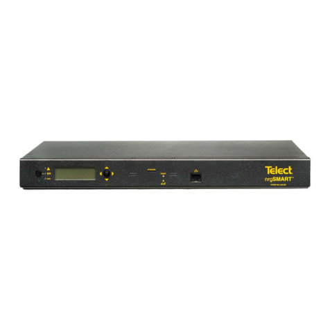
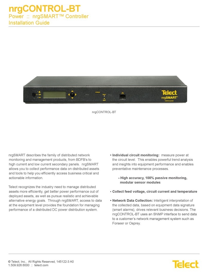
Telect nrgSMART User manual

nrgCONTROL-BT
nrgSMART
nrgSMART
™
™
Controller
Controller
Configuration Guide
nrgOS 3.1.1

© Telect, Inc. All rights reserved. 3.22.17 v.3
1.509.926.6000 :: telect.com 2
nrgSMART
nrgSMART
™
™
Controller Configuration Guide
Controller Configuration Guide
POWER ::
POWER ::
User Guide
User Guide
Table of Contents
1. Introduction......................................................................................................................6
1.1 Connect Controller..................................................................................................6
1.2 Configuration Wizard Display..................................................................................7
1.3 About this Guide......................................................................................................8
2. Controller Tab ..................................................................................................................8
2.1 Term Interpretation..................................................................................................8
2.2 Controller Tab Settings............................................................................................9
2.3 Firmware Upgrade Procedure...............................................................................19
3. Site Tab Settings............................................................................................................25
4. Panels Tab Settings.......................................................................................................28
5. Equipment Tab Settings.................................................................................................52
5.1 Importing CSV and Adding Equipment.................................................................56
6. Supplementary Information............................................................................................65
6.1 MIB Table.................................................................................................................65
6.2 Fuse/Circuit Breaker Ratings...................................................................................65
6.3 GMT Fuses ..............................................................................................................68

© Telect, Inc. All rights reserved. 3.22.17 v.3
1.509.926.6000 :: telect.com 3
nrgSMART
nrgSMART
™
™
Controller Configuration Guide
Controller Configuration Guide
POWER ::
POWER ::
User Guide
User Guide
List of Figures
Figure 1 - nrgBDFB Connections..........................................................................................4
Figure 2 - nrgSMART™Distributed Network Monitoring and Connections..........................5
Figure 3 - nrgSMART Controller to PC Connection..............................................................6
Figure 4 - Connection Successful - nrgSMART Configuration Wizard Opens......................6
Figure 5 - Controller Tab.......................................................................................................7
Figure 6 - Site Tab ................................................................................................................7
Figure 7 - Panels Tab............................................................................................................7
Figure 8 - Equipment Tab .....................................................................................................7
Figure 9 - Controller Tab Window.........................................................................................9
Figure 10 - Controller Information Screen ..........................................................................11
Figure 11 - Controller Information - More info/Less info Screen.........................................12
Figure 12 - Save/Restore Configuration Screen.................................................................14
Figure 13 - Measurement Settings Screen.........................................................................15
Figure 14 - LAN Configuration Screen................................................................................16
Figure 15 - SNMP Screen...................................................................................................18
Figure 16 - Site Tab Window...............................................................................................25
Figure 17 - Site Information Screen....................................................................................26
Figure 18 - Panels Tab Window..........................................................................................28
Figure 19 - BDFB and Panels Screen ................................................................................30
Figure 20 - Sort Order Screen............................................................................................31
Figure 21 - Panel Information Screen.................................................................................32
Figure 22 - Quad System....................................................................................................35
Figure 23 - Dual System.....................................................................................................37
Figure 24 - Panel Information More info/Less info Screen .................................................38
Figure 25 - Circuit Configuration Screen ............................................................................39
Figure 26 - Circuit Settings Window ...................................................................................41
Figure 27 - Panels Settings Screen....................................................................................42
Figure 28 - Feed Alarms Screen.........................................................................................43
Figure 29 - Voltage Sensors Screen and Temperature Sensors Screen............................46
Figure 30 - Current Sensors Screen...................................................................................48
Figure 31 - Equipment Tab Window....................................................................................52
Figure 32 - Equipment Models, Add Equipment and Equipment........................................53
Figure 33 - New Equipment Information Window/Equipment Information Screen..............54
Figure 34 - Equipment Power Source Screen....................................................................63
Figure 35 - Equipment Power Summary Screen................................................................64

© Telect, Inc. All rights reserved. 3.22.17 v.3
1.509.926.6000 :: telect.com 4
nrgSMART
nrgSMART
™
™
Controller Configuration Guide
Controller Configuration Guide
POWER ::
POWER ::
User Guide
User Guide
Figure 1 - nrgBDFB Connections
The nrgBDFB has a built-in controller that has a LAN connection port and nrgNET outputs that connect to 22 external nrgSMART panels and
up to eight internal nrgBDP panels.
Left Daisy
Chain
Configuration
Chassis Ground
nrgNET OUT
nrgNET IN
nrgNET OUT
nrgNET IN
nrgNET OUT
nrgNET IN
nrgNET IN
nrgNET OUT
Right Daisy
Chain
Configuration
nrg600BT08-M
nrg100GMT10-M
Site Controller
Local LAN
Connection SNMP
nrgBDFB

© Telect, Inc. All rights reserved. 3.22.17 v.3
1.509.926.6000 :: telect.com 5
nrgSMART
nrgSMART
™
™
Controller Configuration Guide
Controller Configuration Guide
POWER ::
POWER ::
User Guide
User Guide
Figure 2 - nrgSMART™Distributed Network Monitoring and Connections
SNMP
nrgCONTROL-BT
Local LAN Connection
Chassis Ground
DC Power
Connection
nrg100GMT10-M-BT
nrgNET Out
The nrgCONTROL-BT connects to the local LAN connection port and nrgNET outputs connect to 30 external nrgSMART panels.

© Telect, Inc. All rights reserved. 3.22.17 v.3
1.509.926.6000 :: telect.com 6
nrgSMART
nrgSMART
™
™
Controller Configuration Guide
Controller Configuration Guide
POWER ::
POWER ::
User Guide
User Guide
1. Introduction
To hook up the controller to a laptop or desktop computer:
1. Apply power to the computer and controller.
2. Attach Ethernet cable into the port on the PC.
3. Attach the other end of the Ethernet cable into the LAN port
on the front of the controller. (See Figure 3)
4. Open your internet browser.
• Browsers supported include:
* Chrome (recommended)
* Firefox
5. In the URL field enter http://192.168.1.1 and press return.
The controller is now connected and the nrgSMART
Configuration Guide will open. (See Figure 4)
Controller configuration software sets the structure of nrgSMART’s system operation. It configures various parameters that define site labels,
panel labels and circuit specific labels, thresholds and behaviors which instruct the controller to implement measures that facilitate equipment
operation, monitoring and control.
1.1 Connect Controller
Figure 3 - nrgSMART Controller to PC Connection
Figure 4 - Connection Successful -
nrgSMART Configuration Wizard Opens

© Telect, Inc. All rights reserved. 3.22.17 v.3
1.509.926.6000 :: telect.com 7
nrgSMART
nrgSMART
™
™
Controller Configuration Guide
Controller Configuration Guide
POWER ::
POWER ::
User Guide
User Guide
Controller Tab:View or modify controller information in the
Controller Tab Window
and in the following screens:
Controller Information, Save/
Restore Configuration, Measurement Settings, LAN Configuration and SNMP.
Site Tab:View or modify site specific information in the
Site Tab Window
and in the
Site Information Screen
.
Panels Tab:View or modify panel information in the
Panels Tab Window
and in the following screens/windows:
Panels, Sort Order, Panel
Information, Circuit Configuration, Advanced (Panel Settings, Feed Alarms, Voltage Sensors, Temperature Sensors
and
Current Sensors)
.
Equipment Tab:View or modify equipment information in the
Equipment Tab Window
and in the following screens:
Equipment,
Equipment Models, Equipment Information, Equipment Power Source
and
Equipment Power Summary
.
When connected to the nrgSMART Configuration Wizard, four tabs—Controller, Site, Panels and Equipment—display at the top of the window.
Each tab contains configuration screens where associated field values can be defined or viewed.
Figure 8 - Equipment Tab
Figure 7 - Panels Tab
Figure 6 - Site Tab
Figure 5 - Controller Tab
1.2 Configuration Wizard Display

© Telect, Inc. All rights reserved. 3.22.17 v.3
1.509.926.6000 :: telect.com 8
nrgSMART
nrgSMART
™
™
Controller Configuration Guide
Controller Configuration Guide
POWER ::
POWER ::
User Guide
User Guide
1.3 About this Guide
This guide provides guidelines to assist in the configuration of the nrgSMART Controller. While care has been taken to define all associated
components of this product, every aspect of controller configuration may not be covered.
Throughout this guide, Notes, Alerts, Cautions, Warnings and Danger notifications may be used to convey important information the user
should pay special attention to.
The
Controller Tab
allows the user to view information and define how the controller communicates with the site, the panels and the
equipment. From this tab, measurement threshold settings are set, local networks defined and monitoring options designated.
2. Controller Tab
2.1 Term Interpretation
SNMP is a way to monitor network devices that are on an IP network. Information is requested by the SNMP Manager and received from a
network device, about the device and connected equipment, and is sent and stored in a Management Information Base (MIB). With baseline
measurements and continuous updates, equipment performance can be tracked and controlled. Additionally, the SNMP Traps protocol sends
alerts instantly whenever an event occurs.
The SNMP Manager uses Simple Network Management Protocol (SNMP) that interacts with a network device and its connected equipment.
Through the Local Area Network (LAN), the SNMP Manager routinely requests information, such as power provisioning, remote site
management and circuit threshold data from network devices in different locations. This information is recorded and stored at a central
Management Information Base (MIB) and can be viewed in a user friendly table. Content displays equipment type and location, performance
and power usage, and monitors threshold levels which can anticipate problems with equipment, mitigating downtime so that maintenance can
be scheduled on a routine basis.
SNMP Traps send instant alerts from the network device when an unusual event occurs. The network device sends these messages without
receiving a request from the SNMP Manager; they are not recorded in the MIB.As soon as an event occurs an alarm is triggered indicating
where the event is. Immediate access to equipment alarms can prevent unnecessary downtime. During an event, an alarm promptly notifies
the local technician who can then make repairs or prevent equipment damage.
Simple Network Management Protocol (SNMP)

© Telect, Inc. All rights reserved. 3.22.17 v.3
1.509.926.6000 :: telect.com 9
nrgSMART
nrgSMART
™
™
Controller Configuration Guide
Controller Configuration Guide
POWER ::
POWER ::
User Guide
User Guide
2.2 Controller Tab Settings
Figure 9 - Controller Tab Window
The
Controller Tab
is comprised of the main window (
Controller Tab Window
) and screens that allow custom settings or display read only
values which are pre-defined. The
Controller Tab Window
contains Reboot and Reset Settings buttons. Within the window are screens that
allow other controller related settings to be defined or viewed.
1
23

© Telect, Inc. All rights reserved. 3.22.17 v.3
1.509.926.6000 :: telect.com 10
nrgSMART
nrgSMART
™
™
Controller Configuration Guide
Controller Configuration Guide
POWER ::
POWER ::
User Guide
User Guide
Controller Tab Window
Ref. Field Type Value Description
1 Saved At Read Only Text The date and time that information in the
Controller Tab
was last saved.
NOTE: When a field is updated within a window or screen in the
Controller Tab, clicking outside of the field saves the information and
updates the Saved At time.
Field settings are:
Never: Data not saved
Date/Time: mm/dd/yyyy HH:MM:SS (AM/PM)
2 Reboot Select Button Reboots the controller and retains settings.
Select the Reboot button to reboot the controller.
3 Reset Settings Select Button Resets the controller.
Select Reset Settings button to reset the controller.
NOTE: Reset settings sets the controller back to factory default including
the IP address.

© Telect, Inc. All rights reserved. 3.22.17 v.3
1.509.926.6000 :: telect.com 11
nrgSMART
nrgSMART
™
™
Controller Configuration Guide
Controller Configuration Guide
POWER ::
POWER ::
User Guide
User Guide
Controller Tab :: Controller Information Screen
Ref. Field Type Value Description
1 Status Read Only Light Light color varies to show the panel of the attached panels.
Green: No alarms present.
Red: One or more alarms present on attached panels, or a panel
is missing.
2 Disk State Read Only Text Micro SD card performance.
Operational: Micro SD card operating normally.
Bad Disk: Micro SD not functioning or is not installed.
3 nrgOS Version (Build) Read Only Text Latest nrgSMART Operating System version.
4 Uptime Read Only Text How long the controller has been operating without interruption or reboot.
Displays as: Days / Hours / Minutes / Seconds
5 Storage Read Only Text Amount of storage space.
Displays as: Storage space in use / Storage space remaining
(Percentage of space left)
6 Clear Log Data Select Button Clears logged data.
Select the Clear Log Data button to remove all data from the log.
7 Number of Panels Active Read Only Text The number of panels in use and how many panels are available.
Displays as: Number of panels active / Number of panels configured
8 Controller Name Input Text Name used to distinguish this controller from another controller within
the network.
Enter the Controller Name. This field accepts up to 40 characters. Valid
characters are upper/lowercase letters, numbers, controller version
and spaces.
9 More Info/Less Info Select Toggle View more or fewer screen fields.
Toggle More info to expand the screen and display additional fields or
Less info to hide a portion of the screen.
Figure 10 - Controller Information Screen
1
2
3
4
5
78
6
9

© Telect, Inc. All rights reserved. 3.22.17 v.3
1.509.926.6000 :: telect.com 12
nrgSMART
nrgSMART
™
™
Controller Configuration Guide
Controller Configuration Guide
POWER ::
POWER ::
User Guide
User Guide
Controller Tab :: Controller Information Screen
Ref. Field Type Value Description
10 Controller Serial Number Read Only Text A 12-digit serial number mounted on the controller consisting of
uppercase letters and numbers.
11 Controller Manufacturer Date Read Only Text The date the controller was manufactured.
Displays as: mm/dd/yyyy
12 Controller Part Number Read Only Text A string of characters that identify the controller as a part consisting of 18
upper/lowercase letters, numbers and symbols. Part numbers that are
longer than 18 characters will be truncated.
13 Controller Type Read Only Text Describes the type of controller installed.
14 Controller Board Serial Number Read Only Text A 12-digit serial number mounted on the Controller Board consisting of
uppercase letters and numbers.
15 Controller Board Manufacturer
Date Read Only Text The date the Controller Board was manufactured.
Displays as: mm/dd/yyyy
16 Controller Board Part Number Read Only Text A string of characters that identify the Controller Board as a part
consisting of numbers.
Figure 11 - Controller Information - More info/Less info Screen
23
24
25
10
11 12 13
15
14
16
17
18
19
20
21 22
26
27
28

© Telect, Inc. All rights reserved. 3.22.17 v.3
1.509.926.6000 :: telect.com 13
nrgSMART
nrgSMART
™
™
Controller Configuration Guide
Controller Configuration Guide
POWER ::
POWER ::
User Guide
User Guide
Controller Tab :: Controller Information Screen
Ref. Field Type Value Description
17 UI Board Serial Number Read Only Text A 12-digit serial number mounted on the User Interface Board consisting
of uppercase letters and numbers.
18 UI Board Manufacturer Date Read Only Text The date the controller was manufactured.
Displays as: mm/dd/yyyy
19 UI Board Part Number Read Only Text A six-digit number that identifies the User Interface Board as a part.
20 UI Board Firmware Version Read Only Text The firmware version for the User Interface Board on the controller.
21 UI Board Bootloader Version Read Only Text The bootloader version for the User Interface Board on the controller.
22 UI Board Type Read Only Text Indicates the type of User Interface on the controller consisting of upper/
lowercase letters, numbers, symbols and spaces.
23 Aux. Card Firmware Version Read Only Text The firmware version for the Aux. card in use by the controller.
24 Aux. Card Bootloader Version Read Only Text The bootloader version for the Aux. card in use by the controller.
25 Aux. Card FPGA Version Read Only Text The FPGA version for theAux. card in use by the controller.
26 HTML Revision Read Only Text The HTML revision in use.
27 LAN Firmware Version Read Only Text The firmware version for the Local Area Network in use by the controller.
28 LAN Bootloader Version Read Only Text The bootloader version of the Local Area Network in use by the controller.

© Telect, Inc. All rights reserved. 3.22.17 v.3
1.509.926.6000 :: telect.com 14
nrgSMART
nrgSMART
™
™
Controller Configuration Guide
Controller Configuration Guide
POWER ::
POWER ::
User Guide
User Guide
Controller Tab :: Save/Restore Configuration Screen
Ref. Field Type Value Description
1 Export Settings Select Button Exports configuration settings as a backup and saves them for later use.
Select the Save button to save controller and panel configuration settings.
2 Import Settings Select Button Imports configuration settings for the controller and panel.
Select the Choose File button to browse for a file.
Locate and select the desired .ncs file.
Select Open to import configuration settings.
NOTE: The selected file name will appear next to the Choose File button.
Requires reboot.
3 Import Firmware BNC Select Button Imports firmware BNC.
Select the Choose File button to browse for a file.
Locate and select the desired file.
Select Open to import the file.
NOTE: Once a file has been added it will appear below the Choose File button.
Requires reboot.
Figure 12 - Save/Restore Configuration Screen
12
3
Telect recommends backing up your settings once the controller is configured. This will make sure your settings are saved during future
firmware updates or changes.

© Telect, Inc. All rights reserved. 3.22.17 v.3
1.509.926.6000 :: telect.com 15
nrgSMART
nrgSMART
™
™
Controller Configuration Guide
Controller Configuration Guide
POWER ::
POWER ::
User Guide
User Guide
Controller Tab :: Measurement Settings Screen
Ref. Field Type Value Description
1 Temperature Units Select Drop down
menu Sets how temperature readings will display.
From the Temperature Units drop down menu, select from:
oF: Fahrenheit
oC: Centigrade
Global Fuse Rating Thresholds A percentage of a circuit’s breaker range or fuse range as the threshold value
for alarms.
The following fields allow threshold values to be set to indicate lower or higher
than normally expected current ranges.
2 Lower Critical Select Drop down
menu Lower Critical is a user defined threshold that is a percentage of the Global
Fuse Rating and indicates a lower than expected measurement, defined as a
critical alarm.
Default is: 0%
From the Lower Critical drop down menu, select from: 0% to 100% in
5% increments.
3 Lower Warning Select Drop down
menu Lower Warning is a user defined threshold that is a percentage of the Global
Fuse Rating and indicates a lower than expected measurement, defined as a
warning alarm.
Default is: 0%
From the Lower Warning drop down menu, select from: 0% to 100% in
5% increments.
4 Upper Warning Select Drop down
menu Upper Warning is user defined threshold that is a percentage of the Global
Fuse Rating and indicates a higher than expected measurement, defined as a
warning alarm.
Default is: 60%
From the Upper Warning drop down menu, select from: 0% to 100% in
5% increments.
5 Upper Critical Select Drop down
menu Upper Critical is a user defined threshold that is a percentage of the Global
Fuse Rating and indicates a higher than expected measurement, defined as a
critical alarm.
Default is: 80%
From the Upper Critical drop down menu, select from: 0% to 100% in
5% increments.
Figure 13 - Measurement Settings Screen
1
2
4
5
3

© Telect, Inc. All rights reserved. 3.22.17 v.3
1.509.926.6000 :: telect.com 16
nrgSMART
nrgSMART
™
™
Controller Configuration Guide
Controller Configuration Guide
POWER ::
POWER ::
User Guide
User Guide
Controller Tab :: LAN Configuration Screen
Ref. Field Type Value Description
1 IP Address Input Text Local Area Network IP address identified by a series of numbers
separated by periods.
Enter the LAN IP address. This field accepts four groups of numbers
separated by periods with up to three numbers in each group (a total of
15 characters, including periods). Each group can be in the range
of: 0 - 255.
NOTE: Default IP address is shown above of 192.168.1.1
2 Netmask Input Text Local Area Network Netmask that defines the range of IP addresses
to use.
Enter the LAN Netmask address. This field accepts four groups of
numbers separated by periods with up to three numbers in each group (a
total of 15 characters, including periods). Each group can be in the range
of: 0 - 255.
3 Gateway Input Text Local Area Network Gateway address that is used to bridge networks.
Enter the LAN Gateway address. This field accepts four groups of
numbers separated by periods with up to three numbers in each group (a
total of 15 characters, including periods). Each group can be in the range
of: 0 - 255.
4 DNS Input Text Local Area Network Domain Name Server address.
Enter the LAN DNS address. This field accepts four groups of numbers
separated by periods with up to three numbers in each group (a total of
15 characters, including periods). Each group can be in the range
of: 0 - 255.
Figure 14 - LAN Configuration Screen
1
2
3
456
7
8
9
10
11
12
13

© Telect, Inc. All rights reserved. 3.22.17 v.3
1.509.926.6000 :: telect.com 17
nrgSMART
nrgSMART
™
™
Controller Configuration Guide
Controller Configuration Guide
POWER ::
POWER ::
User Guide
User Guide
Controller Tab :: LAN Configuration Screen
Ref. Field Type Value Description
5 Configured Speed
and Duplex Select Drop down
menu Manually set the Speed and Duplex of the LAN Ethernet port. There are
five options:
Auto-negotiate
100 Mbps Full Duplex
100 Mbps Half Duplex
10 Mbps Full Duplex
10 Mbps Half Duplex
NOTE: Telect recommends manually setting your Speed and Duplex to
the negotiated speed on initial connection. Default is Auto-negotiate.
6 Actual Speed and Duplex Read Only Text Displays the actual Speed and Duplex the Ethernet port is connected at.
7 MAC Read Only Text Displays the Wide Area Network MAC address as six 2-digit characters
separated by a colon.
8 LAN Settings “Apply” Select Button After changing LAN settings you must select the “apply” button for
changes to take affect.
9 Server Name/IP (LAN Ping) Input Text You can ping a remote computer or server to verify connectivity. Insert IP
address of that device here.
10 Number of Pings Input Text Insert the number of pings you want to send to the remote device.
Default is 1.
11 Ping from LAN Select Button Start the pinging sequence to the remote device.
12 Stop Pings Select Button Stop the pinging sequence to the remote device.
13 Clear Ping Data Select Button Remove the ping responses from remote devices.

© Telect, Inc. All rights reserved. 3.22.17 v.3
1.509.926.6000 :: telect.com 18
nrgSMART
nrgSMART
™
™
Controller Configuration Guide
Controller Configuration Guide
POWER ::
POWER ::
User Guide
User Guide
Controller Tab :: SNMP Screen
Ref. Field Type Value Description
1 V1 Requests Select Drop down
Menu Allows use of SNMP Version 1 protocol. SNMP must be enabled for this
field to allow input.
From the Version 1 drop down menu, select Enabled to allow Version 1
protocol or select Disabled to prevent it.
Note: Version 1 has no security. When Version 1 is enabled, associated
fields can be defined.
2 Read Community Input Text Defines the community body to have Version 1 Read rights.
SNMP and Version 1 must be enabled for this field to allow input.
Enter the community string to have SNMP V1 Read rights.
Generally, this field displays either “public” or “private” although other
groups or individual names can be added. This field accepts up to 19
characters. Valid characters are upper/lowercase letters, numbers,
symbols and spaces.
3 Write Community Input Text Defines the community body to have Version 1 Write rights.
SNMP and Version 1 must be enabled for this field to allow input.
Enter the community string to have SNMP V1 Write rights.
Generally, this field displays either “public” or “private” although individual
names can be added as well. If no V1 Write rights are to be assigned,
leave this field blank. This field accepts up to 19 characters. Valid
characters are upper/lowercase letters, numbers, symbols and spaces.
4 V2c Traps Select Drop down
menu SNMP Traps allows the network device to send an alert without receiving
a request from the SNMP Manager. Alerts are sent at the time an event
(i.e. fuse alarm, threshold alarm error, etc.) occurs and are not stored in
the MIB.
SNMP must be enabled for this field to allow input.
From the SNMP Traps drop down menu, select Enabled to allow SNMP
Traps or select Disabled to prevent them. When set to Enabled, the
SNMP Traps IP fields can be defined.
5 V2c Trap IP Input Text The Network Management System’s IP address that will receive the
SNMP Traps message. SNMP and SNMP Traps must be enabled for this
field to allow input.
Enter the IP address that will receive the SNMP Traps message. This
field accepts four groups of numbers separated by periods with up to
three numbers in each group (a total of 15 characters, including periods).
Figure 15 - SNMP Screen
3
2
5
1
4

© Telect, Inc. All rights reserved. 3.22.17 v.3
1.509.926.6000 :: telect.com 19
nrgSMART
nrgSMART
™
™
Controller Configuration Guide
Controller Configuration Guide
POWER ::
POWER ::
User Guide
User Guide
2.3 Firmware Upgrade Procedure
Step 1: Export settings to save by clicking “Save” next to Export Settings
Step 2: Wait until browser begins download of settings file.
NOTE: This could take a few minutes if the controller has a lot of panels or settings.

© Telect, Inc. All rights reserved. 3.22.17 v.3
1.509.926.6000 :: telect.com 20
nrgSMART
nrgSMART
™
™
Controller Configuration Guide
Controller Configuration Guide
POWER ::
POWER ::
User Guide
User Guide
Step 3: Save the settings in a folder where it won’t be lost. It saves to the downloads folder by default. Verify file has been saved into specified
folder when complete.
Step 5: Navigate to where the BNC file is located and select it.
Step 4: After settings are saved, click Choose File next to Import Firmware BNC.
Table of contents
Other Telect Controllers manuals
Popular Controllers manuals by other brands

Emerson
Emerson Fisher 785C Instruction manual supplement
Crane Source
Crane Source Space Vector SFV1000 Installation, Programming & Service manual
Mitsubishi Electric
Mitsubishi Electric MR-MQ100 user manual
ABB
ABB AC500-eCo Series Hardware Introduction
Code
Code MINI 1000 user manual
Eltorque
Eltorque QT250 user manual
