manuals.online logo
Brands
  1. Home
  2. •
  3. Brands
  4. •
  5. Hitachi
  6. •
  7. Controllers
  8. •
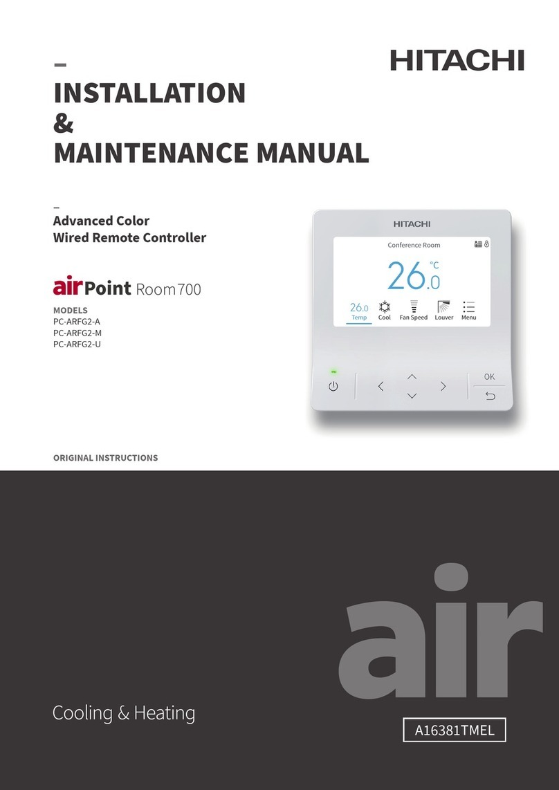
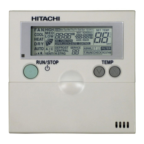
  9. Hitachi Eco Compact PC-ARC-A Instruction Manual

Hitachi Eco Compact PC-ARC-A Instruction Manual

A12109620A
–
INSTALLATION
& MAINTENANCE MANUAL
–
Eco Compact
Wired Remote Controller
MODELS
PC-ARC-A
PC-ARC-M
PC-ARC-U
ORIGINAL INSTRUCTIONS
Important Notice
i
Important Notice
• Johnson Controls-Hitachi Air Conditioning pursues a policy of continuing improvement in design and performance in its
products. As such, Johnson Controls-Hitachi Air Conditioning reserves the right to make changes at any time without prior
notice.
•
Johnson Controls-Hitachi Air Conditioning cannot anticipate every possible circumstance that might involve a potential hazard.
• This heat pump air conditioning unit is designed for standard air conditioning applications only.
Do not use this unit for anything other than the purposes for which it was intended for.
• The installer and system specialist must safeguard against leakage in accordance with local pipetter and electrical
codes. The following standards may be applicable, if local regulations are not available. International Organization for
Standardization: (ISO 5149 or European Standard, EN 378). No part of this manual may be reproduced in any way without the
expressed written consent of Johnson Controls-Hitachi Air Conditioning.
• If you have questions, please contact your distributor or dealer.
• This manual should be considered as a permanent part of the air conditioning equipment and should remain with the
controller.
Product Inspection upon Arrival
1. Upon receiving this product, inspect it for any damages incurred in transit. Claims for damage, either apparent or concealed,
should be led immediately with the shipping company.
2. Check the model number, electrical characteristics (power supply, voltage, and frequency rating), and any accessories to
determine if they agree with the purchase order.
3. The standard utilization for this unit is explained in these instructions. Use of this equipment for purposes other than what it
designed for is not recommended.
4. Please contact your local agent or contractor as any issues involving installation, performance, or maintenance arise. Liability
does not cover defects originating from unauthorized modications performed by a customer without the written consent
of Johnson Controls-Hitachi Air Conditioning. Performing any mechanical alterations on this product without the consent of
the manufacturer renders your warranty null and void.
Important Notice
ii
Table of Contents
Table of Contents
1. Safety Summary ............................................................................................................................................................... 1
2. Installation Work .............................................................................................................................................................. 6
3. Electrical Wiring.............................................................................................................................................................. 10
4. Test Run .......................................................................................................................................................................... 12
5. Function Selection ......................................................................................................................................................... 13
6. Input/Output Setting...................................................................................................................................................... 33
7. Main Remote Setting...................................................................................................................................................... 36
8. Operation Lock/Unlock Setting .................................................................................................................................... 38
9. NFC Setting .................................................................................................................................................................... 39
10.
Adjusting Date/Time ........................................................................................................................................................ 41
11.
Check Menu ...................................................................................................................................................................... 43
1. Safety Summary
1
1. Safety Summary
Indicates a hazardous situation that, if not avoided, could result in death or serious injury.
Indicates a hazardous situation that, if not avoided, could result in minor or moderate injury.
Indicates information considered important, but not hazard-related (for example,
messages relating to property damage).
For the operation of the product, please read and follow this safety summary strictly. Otherwise, improper operation may cause
injury or death.
Signal Words
1. Safety Summary 1. Safety Summary
2
To reduce the risk of serious injury or death, read these instructions thoroughly and follow
all warnings or cautions included in all manuals that accompanied the product and are
attached to the unit. Refer back to these safety instructions as needed.
• This system, including this controller, should be installed by personnel certied by Johnson Controls-Hitachi Air Conditioning.
Personnel must be qualied according to local, state, and national building and safety codes and regulations. Incorrect
installation could cause leaks, electric shock, re, or an explosion. In areas where Seismic Performance requirements are
specied, the appropriate measures should be taken during installation to guard against possible damage or injury that might
occur in an earthquake. If the unit is not installed appropriately correctly, injuries may occur because of a falling unit.
• Use appropriate Personal Protective Equipment (PPE), such as gloves, protective goggles, and electrical protection equipment
and tools suited for electrical operation purposes.
• When transporting, be careful when picking up, moving and mounting these units. Although the controller may be packed
using plastic straps, do not use them for transporting from one location to another.
Do not stand on or put any material on the controller.
• When installing the controller cabling to the units, do not touch or adjust any safety devices inside the indoor or outdoor units.
All safety features, disengagement, and interlocks must be in place and functioning correctly before the equipment is put into
operation. If these devices are improperly adjusted or tampered with in any way, a serious accident can occur. Never bypass,
wire around, or jump-out any safety device or switch.
• Use only Johnson Controls-Hitachi Air Conditioning recommended, provided as standardized, or replacement parts.
• Johnson Controls-Hitachi Air Conditioning will not assume any liability for injuries or damage caused by not following steps
outlined or described in this manual. Unauthorized modications to Johnson Controls-Hitachi Air Conditioning products are
prohibited as they…
○May create hazards that could result in death, serious injury or equipment damage;
○Will void product warranties;
○May invalidate product regulatory certications.
General Precautions
1. Safety Summary
3
• If the wired controller is installed in a location where electromagnetic energy is generated, make sure that the wired controller
is shielded and cables are sleeved inside conduit tubing.
• If there is a source of electrical interference near the power source, install noise suppression equipment (lter).
• During the test run, check the unit’s operation temperature. If the unit is used in an environment where the temperature
exceeds the operation boundary, it may cause severe damage. Check the operation temperature boundary in the manual. If
there is no specied temperature, use the unit within the operation temperature boundary of 32°F to 104°F (0°C to 40°C).
• Perform properly electrical wiring work. The details of the electrical wiring connection are described in the "Electrical Wiring"
of corresponding Installation and Maintenance Manual.
• Read this installation and maintenance manual for proper electrical wiring work.
Take the following precautions to reduce the risk of property damage.
• Do not touch the main circuit board or electronic components in the controller or remote devices.
Make sure that dust and/or steam does not accumulate on the circuit board.
• When installing the unit in a hospital or other facility where electromagnetic waves are generated from nearby medical and/or
electronic devices, be prepared for noise and Electromagnetic Interference (EMI). Do not install where the waves can directly
radiate into the electrical box, controller cable, or controller. Inverters, appliances, high-frequency medical equipment, and
radio communications equipment. EMI may cause the unit to malfunction. The operation of the unit may also adversely aect
these same devices. Install the unit at least 10 . (approximately 3m) away from such devices.
• Locate the controller at a distance of at least 3 . (approximately 1m) from the electric lighting. Otherwise, the receiver part of
the controller may have diiculty receiving operation commands.
1. Safety Summary 1. Safety Summary
4
Installation Precautions
Take the following precautions to reduce the risk of electric shock, fire, or explosion
resulting in serious injury or death.
• If the remote sensors are not used with this controller, then do not install this controller…
○In a room where there is no thermostat.
○Where the unit is exposed to direct sunshine or direct light.
○Where the unit is in close proximity to a heat source.
○Where hot/cold air from the outdoors, or a dra from elsewhere (such as air vents, diusers, or grilles) can aect air circulation.
○In areas with poor air circulation and ventilation.
• Perform a test run using the controller to ensure normal operation. Safety guards, shields, barriers, covers, and protective
devices must be in place while the compressor/unit is operating. During the test run, keep ngers and clothing away from any
moving parts.
After installation work for the system has been completed, explain the "Safety Precautions," use, and maintenance of the unit to
the customer according to the information in all manuals that accompanied the system. All manuals and warranty information
must be given to the user or left near the Indoor Unit.
Take the following precautions to reduce the risk of electric shock, fire, or explosion
resulting in serious injury or death:
• Only use electrical protection equipment and tools suited for this installation.
• Insulate the wired controller against moisture and temperature extremes.
• Use specied cables between units and the controller.
• Communication cabling must be a minimum of 18-Gauge, 2-Conductor, Stranded Copper.
Shielded cable must be considered for applications and routing in areas of high EMI and other sources of potentially excessive
electrical noise to reduce the potential for communication errors. When shielded cabling is applied, proper bonding and
Electrical Precautions
1. Safety Summary
5
termination of the cable shield is required as per Johnson Controls-Hitachi Air Conditioning guidelines. Plenum and riser
ratings for communication cables must be considered per application and local code requirements.
• The polarity of the input terminals is important, so be sure to match the polarity when using contacts that have polarity.
•
Highly dangerous electrical voltages may be used in this system. Carefully refer to the wiring diagram and these instructions when
wiring. Improper connections and inadequate grounding can cause serious injury or death.
• Before installing the controller or remote devices, ensure that the indoor and outdoor unit operation has been stopped.
Further, be sure to wait at least ve minutes before turning o the main power switch to the indoor or outdoor units.
Otherwise, water leakage or electrical breakdown may result.
•
Do not open the service cover or access panel to the indoor or outdoor units without turning OFF the main power supply. Before
connecting or servicing the controller or cables to indoor or outdoor units, open and tag all disconnect switches. Never assume
electrical power is disconnected. Verify with a meter and equipment.
• Use an exclusive power supply at the controller’s rated voltage.
• Be sure to install circuit breakers (ground fault interrupter, isolating switch, molded case circuit breaker, and so forth) with the
specied capacity. Ensure that the wiring terminals are tightened securely to recommended torque specications.
• Clamp electrical wires securely with a cord clamp aer all wiring is connected to the terminal block.
In addition, run wires securely through the wiring access channel.
• When installing the power lines, do not apply tension to the cables. Secure the suspended cables at regular intervals, but not
too tightly.
• Make sure that the terminals do not come into contact with the surface of the electrical box.
If the terminals are too close to the surface, it may lead to failures at the terminal connection.
• Do not pour water on the controller as it could cause electric shock and/or damage the unit.
Do not use strong detergent such as a solvent. Clean with a so cloth.
• Check that the ground wire is securely connected. Do not connect ground wiring to gas piping, water piping, lighting
conductor, or telephone ground wiring.
1. Safety Summary 2. Installation Work
6
2. Installation Work
[Before Installation]
(1) This packing contains the following parts.
Name PC-ARC-*Operation Manual Installation & Maintenance
Manual Screw Connecting Wire
Appearance
M4 × 16mm
Qty. 1 2▲2▲2 1
▲The manual quantity maybe one in some regions.
(2) When arranging the eco compact wired remote controller and other
controllers vertically, place them at least 2 inches(50mm) apart.
more than 2 inches(50mm
)
2. Installation Work
7
[Installation Procedures]
(1) Insert the edge of the slotted screwdriver into the groove at the bottom of the holding bracket, push and turn
the slotted screwdriver to separate and remove the controller from the holding bracket.
Groove Part
Figure Seen from Bottom Side
Slotted
Approx. 1/4 inches(6mm)
Screwdriver
NOTE:
• Do not insert the slotted screwdriver into the tab part beside the groove. The tab may be damaged and the eco
compact wired remote controller cannot be installed.
Tabs for Attaching Controller
Holding Bracket


上
上


2. Installation Work 2. Installation Work
8
(2) According to different controller installation methods, choose one of the following two ways to install the
holding bracket and connect the cable .
Way 1. For controller that will be installed on the wall, conduct holding bracket installation and cable
connection by followings steps:
a. Secure the holding bracket onto the wall with screws (accessory).
b. Plug the connector of the connecting wire into the CN1.
c. Connect wire stuck in the slot.
d. Attach the stopper (plastic band) to the cable at the inside of the draw-out hole.
d
Band Stopper
(Field-Supplied)
Cable Draw-out Hole
b
c
CN1


上
上


a
2. Installation Work
9
86*86 Junction Box
(Field-supplied)
M4 Screws
(Field-supplied)
Cable Connection
Holding Bracket
Way 2. For controller that will be installed on the 86*86 Junction Box,
(3) Attach the controller body to the mounted holding bracket.
Be careful not to pinch the cable when attaching it.


上
上


Remove the
protective film.
(4) After installation, remove the protective film from the LCD screen.
conduct holding bracket installation and cable connection by
followings steps:
a. Prepare eld-supplied implanted 86*86 junction box.
b. Feed the cable through the conduit tube in the wall.
c. Connect the accessory cable to the eld-supplied cable by
soldering. Insulate the connecting part with tape.
d. Secure the holding bracket to the junction box with M4
screws.
2. Installation Work 3. Electrical Wiring
10
ATTENTION:
Disconnect all power at the main power source before performing electrical work. Failure to do this can result
in fire, damage to internal components, and severe or fatal electrical shock.
Max. 16 Indoor Units
Controller
CN1
Controller
(Secondary)
Electrical Box
of Indoor Unit
Electrical Box
of Indoor Unit
Terminal Board Terminal Board
M3.5
Screws
M3.5
Screws
Use AWG 18 (0.82mm

) cable, (18-Gauge, 2-Conductor, Stranded Copper).
AA
BB CN1
Example of Communication Cabling:
3. Electrical Wiring
•
Communication cabling must be a minimum of 18-Gauge, 2-Conductor, Stranded Copper. Shielded cable must
be considered for applications and routing in areas of high electronic interference (EMI) and other sources of
potentially excessive electrical noise to reduce the potential for communication errors. When shielded cabling
is applied, proper bonding and termination of the cable shield is required as per Johnson Controls-Hitachi
3. Electrical Wiring
11
Air Conditioning guidelines. Plenum and riser ratings for communication cables must be considered per
application and local code requirements.
The use of any other grade of cable other than that specied above
can result in damage from EMI.
• Maintain a distance more than 11-13/16 inches (30cm) between the communication cables (controller cable
and communication cables) and power source of the indoor units. If this is not done, the unit can malfunction
due to EMI generated by incoming power cables from the power source.
• In systems where multiple indoor units are in synchronized control under a single controller, assign the
refrigerant cycle numbers and address for indoor units without duplication.
• Refer to the "Unit No. Setting" of each Installation and Maintenance manual provided with indoor unit when
performing electrical wiring work between the controller and indoor units for setting the refrigerant cycle
number and the indoor unit address.
• No gap should exist between the controller cable and the cable access inlet of the controller box casing. If
there is a gap, cover and seal the gap with vinyl tape. Failure to insulate against the penetration of moisture
and insects can result in degraded performance and damage to the unit.
• If case of operating with two controllers (Primary and Secondary), set the primary and secondary controllers
by selecting the appropriate function for those controllers. Refer to Page 19 item F2 in chapter 5. Function
Selection. Aer this is set, turn OFF the power supply to all indoor units connected to these controllers.
3. Electrical Wiring 4. Test Run
12
4. Test Run
Step1. Press
" "and " "simultaneously
for 3 seconds to display the
test run screen of OFF state.
Connected Indoor Unit No.
Step2. Press
" "to switch mode and press " "to switch fan
speed.
Step3. Press " "to enter into the test run screen of ON state.
Step4. Press
" "to switch mode and press " "to switch fan
speed, and press " "or " "to set the test run time.
•
The setting time range is from 30 minutes to 600 minutes.
•
Press
" "or " " can adjust the test run time by 30 minutes
with each single press.
Step5. Press
" "to end the test run and return to home screen.
Test Run Time
(120 minutes)
NOTES:
• When a test run request is made from the outdoor unit or central controller, the screen automatically turns to
test run screen.
• After transition to the test run screen, the operation mode and fan speed will remain the same state before the
test run setting.
• In the case of two wired remote controllers, only the primary one can change the test run time.
5. Function Selection
13
5. Function Selection
Step1. Press
" "
for 3 seconds to display the function selection setting
screen.
•If only one indoor unit is connected with the wired remote
controller, Step3 is displayed.
•If multiple indoor units are connected with the wired
remote controller, step2 is displayed.
Step2. Indoor unit selecting screen is displayed.
•
Each indoor unit has its own index number. And the
corresponding refrigerant system number and address
number are displayed on the upper right corner of the screen.
Press
" "or " "
to select the indoor unit by changing the "Index
No". Then press
" "
to conrm the selection.
•
If all the indoor units are selected, the Index No. is indicated
as FF.
Index No.
Indoor Unit No. (refrigerant system)
Address No.
of the
selected unit
Index No.
5. Function Selection 5. Function Selection
14
Step3. Press
" "or " "
to select the setting item. And press
" "to
conrm the selection.
Step4. Press
" "or " "
to switch the set value. Press
""to conrm
the set value, the screen returns to Step3
.
Step5. Press
" "in Step3 or Step4 to return to home screen.
Setting Item
(Flashing)
Set Value
(Flashing)
5. Function Selection
15
Table A. Optional Setting Items for Function Selection
No. Item Optional Function Individual
Setting
Setting
Condition Contents Setting
1 b1 Set heating temperature compensation ○
00
01
02
03
04
Tset +4oC(default setting)(*1)
Tset+0oC(no compensation)
Tset+2oC (*2)
Tset+3oC
Tset+1oC
2 b2 Circulator Function during Heating Thermo-OFF ○00
01
Unavailable
Available
3 b3 Not used × 00
01
00
01
4 b4 Change of lter cleaning period ○
00
01
02
03
04
1200h(default setting)(*3)
100h
1200h
2500h
No Indication
5 b5 Lock operation mode on controller × 00
01
Usual setting
Locked (*4)
6 b6 Lock temperature setting on remote controller × 00
01
Standard
Fixed
7 b7 Set operation mode as Cooling Unit × 00
01
Usual setting
Locked
8 b8 Automatic Cool/Heat operation × 00
01
Unavailable
Available
9 b9 Lock fan speed setting on controller × 00
01
Standard
Locked
10 bA Not used - - Not Used(Use as 00 setting conditions)
11 bb Set cooling temperature compensation ×
00
01
02
Tset+0oC(no compensation, default setting)
Tset–1oC
Tset–2oC
5. Function Selection 5. Function Selection
16
No. Item Optional Function Individual
Setting
Setting
Condition Contents Setting
12 bC Not used - 00
01
00
01
13 bd Not used - 00
01
00
01
14 bE Not used - 00
01
00
01
15 C1 Not used - 00
01
00
01
16 C2 Not used - - Not Used(Use as 00 setting conditions)
17 C3 Not used - 00
01
00
01
18 C4 Not used - 00
01
00
01
19 C5 Static pressure sel. / Increase Fan Hi speed ○
00
01
02
Standard static pressure/ Standard speed
High static pressure/ Hi speed 1(*5)
Low static pressure/ Hi speed 2
20 C6 Increase of fan speed at heating Thermo-OFF ○00
01
Unavailable
Available
21 C7 Cancel 3 min. compressor starting delay ○00
01
Standard
Cancellation
22 C8 Sensor selection for indoor temp. control ○
00
01
02
Indoor air suction sensor/ average air suction-
THM4
Wired controller sensor/ THM4(remote sensor)
Average return air sensor and (controller
sensor or remote sensor)
23 C9 Not used - - Not Used(Use as 00 setting conditions)
24 CA Not used - - Not Used(Use as 00 setting conditions)
25 Cb Selection of forced stoppage logic ○00
01
Normally Open
Normally Closed
5. Function Selection
17
No. Item Optional Function Individual
Setting
Setting
Condition Contents Setting
26 CC Not used - 00
01
00
01
27 Cd Not used - 00
01
00
01
28 CE Not used - 00
01
00
01
29 CF Change of Louver Swing Angle ○
00
01
02
Standard setting (7 steps)
Cold dra (5 steps)
High ceilings (5 steps)
30 d1 Power Supply ON/OFF 1 ○00
01
Unavailable
Available
31 d2 Not used - - Not Used(Use as 00 setting conditions)
32 d3 Power Supply ON/OFF 2 ○00
01
Unavailable
Available
33 d4 Prevention of low air outlet temperature in cooling
mode(*6) ○00
01
Unavailable
Available
34 d5 Prevention of low air outlet temperature in heating
mode ○00
01
Unavailable
Available
35 d6 Not used - 00
01
00
01
36 d7 Not used - 00
01
00
01
37 E1 Not used - 00
01
00
01
38 E2 Not used - 00
01
00
01
39 E3 Not used - 00
01
00
01

Other manuals for Eco Compact PC-ARC-A

1

This manual suits for next models

2

Other Hitachi Controllers manuals

Hitachi S10mini LQS070 User manual

Hitachi

Hitachi S10mini LQS070 User manual

Hitachi HCWA21NEWH User manual

Hitachi

Hitachi HCWA21NEWH User manual

Hitachi ATW-YCC-03 User manual

Hitachi

Hitachi ATW-YCC-03 User manual

Hitachi EHV+ Series Instructions for use

Hitachi

Hitachi EHV+ Series Instructions for use

Hitachi HF-W100E/IoT User manual

Hitachi

Hitachi HF-W100E/IoT User manual

Hitachi HARC-MODBUS User manual

Hitachi

Hitachi HARC-MODBUS User manual

Hitachi PSC-A64S User manual

Hitachi

Hitachi PSC-A64S User manual

Hitachi SPX-WDC5 User manual

Hitachi

Hitachi SPX-WDC5 User manual

Hitachi ECO COMPACT PC-ARC-E User manual

Hitachi

Hitachi ECO COMPACT PC-ARC-E User manual

Hitachi H8/3637 User manual

Hitachi

Hitachi H8/3637 User manual

Hitachi HIDIC EH-150 User manual

Hitachi

Hitachi HIDIC EH-150 User manual
Hitachi HIDIC EH-150 EH-PT4 Instructions for use

Hitachi

Hitachi HIDIC EH-150 EH-PT4 Instructions for use

Hitachi FL.NET User manual

Hitachi

Hitachi FL.NET User manual

Hitachi H Series User manual

Hitachi

Hitachi H Series User manual

Hitachi PC-ARFG-E User manual

Hitachi

Hitachi PC-ARFG-E User manual
Hitachi SJ300 Series User manual

Hitachi

Hitachi SJ300 Series User manual

Hitachi PC-ARF1 Instruction Manual

Hitachi

Hitachi PC-ARF1 Instruction Manual

Hitachi PSC-A16RS User manual

Hitachi

Hitachi PSC-A16RS User manual

Hitachi EH-150 Type I Instructions for use

Hitachi

Hitachi EH-150 Type I Instructions for use

Hitachi S10 Series User manual

Hitachi

Hitachi S10 Series User manual

Hitachi PSC-A128WEB3 User manual

Hitachi

Hitachi PSC-A128WEB3 User manual

Hitachi EH-150 Type I Instructions for use

Hitachi

Hitachi EH-150 Type I Instructions for use

Hitachi HX-CP1S08-0 User manual

Hitachi

Hitachi HX-CP1S08-0 User manual

Hitachi PC-ARF1 User manual

Hitachi

Hitachi PC-ARF1 User manual

Popular Controllers manuals by other brands

Samson TROVIS 5571 Mounting and operating instructions

Samson

Samson TROVIS 5571 Mounting and operating instructions

Unitech UT-1596 Technical manual

Unitech

Unitech UT-1596 Technical manual

FIBARO FIBEFGWCEU-201-B operating manual

FIBARO

FIBARO FIBEFGWCEU-201-B operating manual

Siemens PolyCool CPS 40 Installation and user manual

Siemens

Siemens PolyCool CPS 40 Installation and user manual

ENGO CONTROLS EPC12HW quick guide

ENGO CONTROLS

ENGO CONTROLS EPC12HW quick guide

Controls MVP-238 product manual

Controls

Controls MVP-238 product manual

Gree CE55-24/F owner's manual

Gree

Gree CE55-24/F owner's manual

Imperial 2601 instructions

Imperial

Imperial 2601 instructions

PowerXtreme XS20s user manual

PowerXtreme

PowerXtreme XS20s user manual

Barco EC-30 quick start guide

Barco

Barco EC-30 quick start guide

Weishaupt WRS manual

Weishaupt

Weishaupt WRS manual

Ltech WiFi-101-RGBW Operating	 instruction

Ltech

Ltech WiFi-101-RGBW Operating instruction

ICP DAS USA WISE-52 Series quick start

ICP DAS USA

ICP DAS USA WISE-52 Series quick start

Harman JBL PROFESSIONAL INTONATO 24 Operation manual

Harman

Harman JBL PROFESSIONAL INTONATO 24 Operation manual

RTI KX2 Quick reference guide

RTI

RTI KX2 Quick reference guide

Mitsubishi QCPU Structured programming manual

Mitsubishi

Mitsubishi QCPU Structured programming manual

Control Resources SmartFan Cirrus-6 Installation & operation manual

Control Resources

Control Resources SmartFan Cirrus-6 Installation & operation manual

Mitsubishi Electric Melsec WS Series user manual

Mitsubishi Electric

Mitsubishi Electric Melsec WS Series user manual

manuals.online logo
manuals.online logoBrands
  • About & Mission
  • Contact us
  • Privacy Policy
  • Terms and Conditions

Copyright 2025 Manuals.Online. All Rights Reserved.