TELEDYNE API 452 User manual


Teledyne API Model 452 Ozone Sensor User Manual, 02852H DCN8478
i
Notice of Copyright
© 2015-2022 Teledyne Advanced Pollution Instrumentation. All rights reserved.
Revisions to this Manual are intended to clarify existing descriptions and are not intended to infer any changes
to customers under copy exact requirements.
Trademarks
All trademarks, registered trademarks, brand names or product names appearing in this document are the
property of their respective owners and are used herein for identification purposes only.
Teledyne API Model 452 Ozone Sensor User Manual, 02852H DCN8478
ii
Safety Messages
Important safety messages are provided throughout this manual for the purpose of
avoiding personal injury or instrument damage. Please read these messages
carefully. Each safety message is associated with a safety alert symbol and is
placed throughout this manual; the safety symbols are also located inside the
instrument. It is imperative that you pay close attention to these messages, the
descriptions of which are as follows:
WARNING: Electrical Shock Hazard
HAZARD: Strong oxidizer
GENERAL WARNING/CAUTION: Read the accompanying
message for specific information.
CAUTION: Hot Surface Warning
Do Not Touch: Touching some parts of the instrument without
protection or proper tools could result in damage to the part(s) and/or
the instrument.
Technician Symbol: All operations marked with this symbol are to be
performed by qualified maintenance personnel only.
Electrical Ground: This symbol inside the instrument marks the
central safety grounding point for the instrument.
CAUTION
This product should only be installed, commissioned, and used strictly for the
purpose and in the manner described in this manual. If you improperly install,
commission, or use this instrument in any manner other than as instructed in this
manual or by our Technical Support team, unpredictable behavior could ensue with
possible hazardous consequences.
Such risks, whether during installation and commission or caused by improper
installation/commissioning/use, and their possible hazardous outcomes include but
are not limited to:
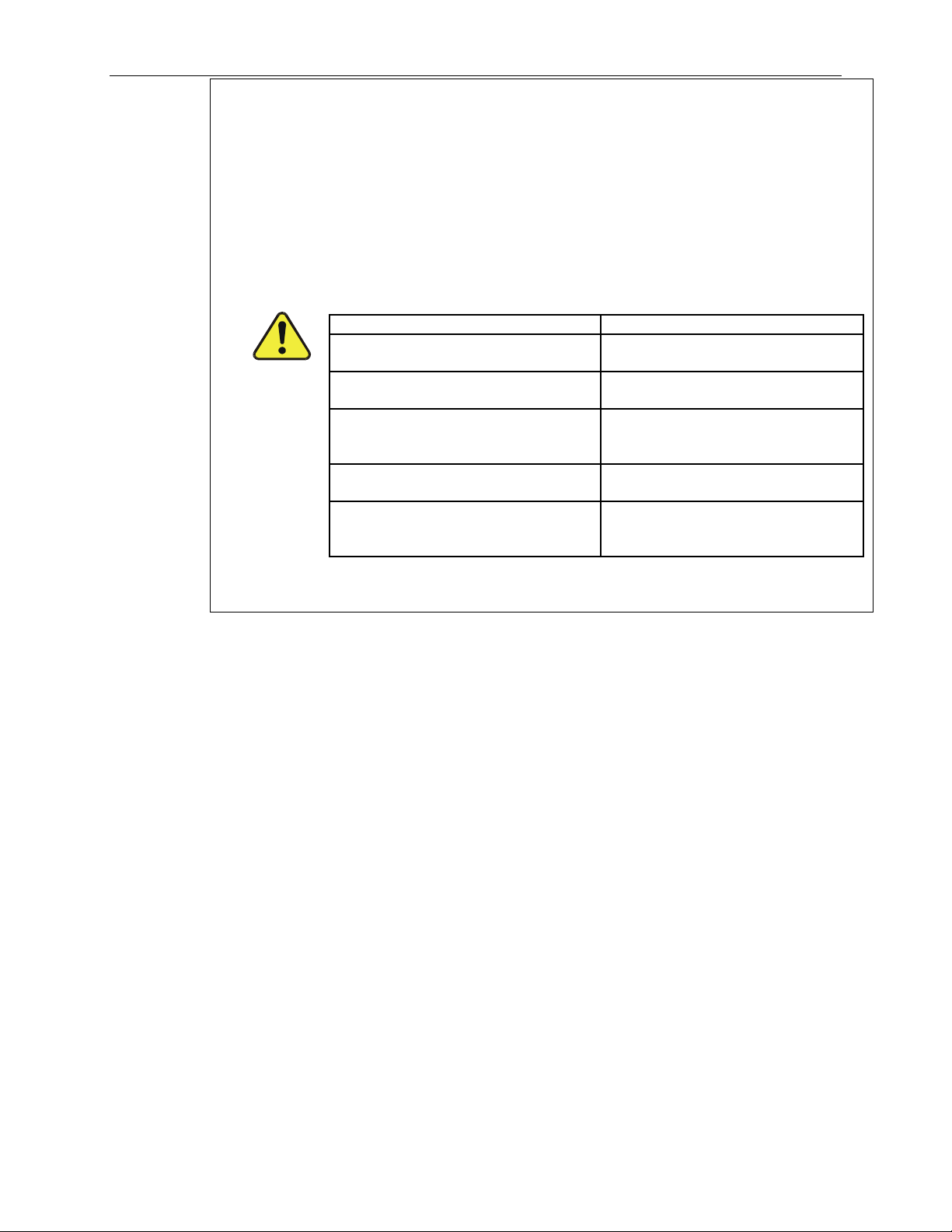
RISK
HAZARD
Liquid or dust/debris ingress
Electrical shock hazard
Improper or worn power cable
Electrical shock or fire hazard
Excessive pressure from improper
gas bottle connections
Explosion and projectile hazard
Sampling combustible gas(es)
Explosion and fire hazard
Improper lift & carry techniques
Personal injury
Note that the safety of a system that may incorporate this product is the end user’s
responsibility.

Teledyne API Model 452 Ozone Sensor User Manual, 02852H DCN8478
iii
Consignes de Sécurité
Des consignes de sécurité importantes sont fournies tout au long du présent
manuel dans le but d’éviter des blessures corporelles ou d’endommager les
instruments. Veuillez lire attentivement ces consignes. Chaque consigne de
sécurité est représentée par un pictogramme d’alerte de sécurité; ces pictogrammes
se retrouvent dans ce manuel et à l’intérieur des instruments. Les symboles
correspondent aux consignes suivantes :
AVERTISSEMENT : Risque de choc électrique
DANGER : Oxydant puissant
AVERTISSEMENT GÉNÉRAL / MISE EN GARDE : Lire la
consigne complémentaire pour des renseignements spécifiques
MISE EN GARDE : Surface chaude
Ne pas toucher : Toucher à certaines parties de l’instrument
sans protection ou sans les outils appropriés pourrait entraîner
des dommages aux pièces ou à l’instrument.
Pictogramme « technicien » : Toutes les opérations portant ce
symbole doivent être effectuées uniquement par du personnel
de maintenance qualifié.
Mise à la terre : Ce symbole à l’intérieur de l’instrument
détermine le point central de la mise à la terre sécuritaire de
l’instrument.
Teledyne API Model 452 Ozone Sensor User Manual, 02852H DCN8478
iv
MISE EN GARDE
Ce produit ne doit être installé, mis en service et utilisé qu’aux fins et de la
manière décrites dans le présent manuel. Si vous installez, mettez en service ou
utilisez cet instrument de manière incorrecte autre que celle indiquée dans ce
manuel ou sous la direction de notre équipe de soutien technique, un
comportement imprévisible pourrait entraîner des conséquences potentiellement
dangereuses.
Ce qui suit est une liste, non exhaustive, des risques et résultats dangereux
possibles associés avec une mauvaise utilisation, une mise en service incorrecte,
ou causés mauvaise commission.
RISQUE
DANGER
Pénétration de liquide ou de
poussière/débris
Risque de choc électrique
Câble d’alimentation incorrect,
endommagés ou usé
Choc électrique ou risque
d’incendie
Pression excessive due à des
connexions de bouteilles de gaz
incorrectes
Risque d’explosion et d’émission
de projectile
Échantillonnage de gaz
combustibles
Risque d’explosion et d’incendie
Techniques de manutention,
soulevage et de transport
inappropriées
Blessure corporelle
Notez que la sécurité d’un système qui peut incorporer ce produit est la
responsabilité de l’utilisateur final.

Teledyne API Model 452 Ozone Sensor User Manual, 02852H DCN8478
v
Warranty
WARRANTY POLICY (02024J)
Teledyne API (TAPI), a business unit of Teledyne Instruments, Inc., provides that:
Prior to shipment, TAPI equipment is thoroughly inspected and tested. Should equipment failure occur, TAPI
assures its customers that prompt service and support will be available. (For the instrument-specific warranty
period, please refer to the “Limited Warranty” section in the Terms and Conditions of Sale on our website at
http://www.teledyne-api.com.
COVERAGE
After the warranty period and throughout the equipment lifetime, TAPI stands ready to provide on-site or in-
plant service at reasonable rates similar to those of other manufacturers in the industry. All maintenance and
the first level of field troubleshooting are to be performed by the customer.
NON-TAPI MANUFACTURED EQUIPMENT
Equipment provided but not manufactured by TAPI is warranted and will be repaired to the extent and
according to the current terms and conditions of the respective equipment manufacturer’s warranty.
Product Return
All units or components returned to Teledyne API should be properly packed for handling and returned freight
prepaid to the nearest designated Service Center. After the repair, the equipment will be returned, freight
prepaid.
The complete Terms and Conditions of Sale can be reviewed at http://www.teledyne-api.com.
CAUTION – Avoid Warranty Invalidation
Failure to comply with proper anti-Electro-Static Discharge (ESD) handling
and packing instructions and Return Merchandise Authorization (RMA)
procedures when returning parts for repair or calibration may void your
warranty. For anti-ESD handling and packing instructions please refer to the
manual, Fundamentals of ESD, PN 04786, in its “Packing Components for
Return to Teledyne API’s Customer Service” section. The manual can be
downloaded from our website at http://www.teledyne-api.com. RMA
procedures can also be found on our website.

Teledyne API Model 452 Ozone Sensor User Manual, 02852H DCN8478
vi
Table of Contents
NOTICE OF COPYRIGHT ........................................................................................................................... I
TRADEMARKS .............................................................................................................................................. I
SAFETY MESSAGES....................................................................................................................................II
CONSIGNES DE SÉCURITÉ..................................................................................................................... III
WARRANTY ..................................................................................................................................................V
TABLE OF CONTENTS ............................................................................................................................. VI
LIST OF FIGURES.....................................................................................................................................VII
LIST OF TABLES.......................................................................................................................................VII
1 PRODUCT DESCRIPTIONS ..................................................................................................................1-1
1.1 MODEL 452 PROCESS OZONE SENSOR ................................................................................................ 1-1
2 SPECIFICATIONS AND APPROVALS ................................................................................................2-1
2.1 MECHANICAL SPECIFICATIONS ........................................................................................................... 2-1
2.2 PERFORMANCE SPECIFICATIONS ......................................................................................................... 2-2
2.3 OPERATING LIMITS ............................................................................................................................. 2-2
2.4 ELECTRICAL SPECIFICATIONS ............................................................................................................. 2-2
2.5 CALIBRATION REFERENCE.................................................................................................................. 2-2
2.6 PRESSURE DROP ................................................................................................................................. 2-3
2.7 APPROVALS ........................................................................................................................................ 2-3
3 THEORY OF OPERATION ....................................................................................................................3-1
4 INSTALLATION ......................................................................................................................................4-1
4.1 UNPACKING ........................................................................................................................................ 4-1
4.2 MECHANICAL INSTALLATION ............................................................................................................. 4-1
4.3 ELECTRICAL CONNECTIONS................................................................................................................ 4-2
4.3.1 Power Supply........................................................................................................................... 4-2
4.3.2 Analog Output.......................................................................................................................... 4-2
4.3.3 Zero Calibration Input............................................................................................................. 4-3
4.3.4 Status Outputs.......................................................................................................................... 4-3
4.3.5 RS232/485 Interface ................................................................................................................ 4-3
4.4 GAS CONNECTIONS............................................................................................................................. 4-4
4.5 START-UP AND CALIBRATION PROCEDURE ........................................................................................ 4-4
5 COMMUNICATIONS..............................................................................................................................5-1
5.1.1 RS485/RS232 Commands ........................................................................................................ 5-1
5.1.2 Sample Serial Port Code ......................................................................................................... 5-2
6 MAINTENANCE: UV LAMP REPLACEMENT / ADJUSTMENT ...................................................6-1
7 SENSOR AND SYSTEM TROUBLESHOOTING ................................................................................7-1
7.1 STATUS LEDS..................................................................................................................................... 7-1
7.2 STATUS OUTPUTS ............................................................................................................................... 7-2
7.2.1 Sensor OK................................................................................................................................ 7-2
7.2.2 Invalid Reading........................................................................................................................ 7-2
7.2.3 Lamp Low ................................................................................................................................ 7-3
7.2.4 Cell Dirty ................................................................................................................................. 7-3
7.2.5 Status Output Summary Table ................................................................................................. 7-3
7.3 NO COMMUNICATION ......................................................................................................................... 7-3
7.4 TECHNICAL ASSISTANCE .................................................................................................................... 7-5

Teledyne API Model 452 Ozone Sensor User Manual, 02852H DCN8478
vii
List of Figures
FIGURE 2-1: MODEL 452 HIGH PURITY OZONE SENSOR ..................................................................................2-1
FIGURE 2-2: PRESSURE DROP VS.FLOW...........................................................................................................2-3
FIGURE 4-1: ELECTRICAL CONNECTIONS .........................................................................................................4-2
FIGURE 4-2: DIGITAL OUTPUT CONNECTIONS..................................................................................................4-3
FIGURE 6-1: COVER ASSEMBLY SCREWS ..........................................................................................................6-2
FIGURE 6-2: UV LAMP ORIENTATION...............................................................................................................6-2
FIGURE 6-3: VOLTAGE ADJUSTMENT LOCATIONS ............................................................................................6-3
List of Tables
TABLE 7-1: STATUS OUTPUTS ..........................................................................................................................7-2
TABLE 7-2: STATUS OUTPUT TRUTH TABLE ....................................................................................................7-3

Teledyne API Model 452 Ozone Sensor User Manual, 02852H DCN88478
1-1
1 Product Descriptions
1.1 Model 452 Process Ozone Sensor
The Teledyne API Model 452 is a microprocessor-based sensor for measuring the concentration of
gaseous ozone in processes such as semiconductor wafer fabrication, water treatment, and ozone
research. The Model 452 can be used as a full flow process sensor or as a sensor to monitor a
small flow of gas diverted from a process stream.
The Model 452 features a standard 0-5 volt analog signal for reporting process concentration as
well as 4 digital status outputs for sensor diagnostics. A bi-directional serial interface is also
provided for computer control.
The Model 452 operates from an external +15 vdc power source.

Teledyne API Model 452 Ozone Sensor User Manual, 02852H DCN8478
2-1
2 Specifications and Approvals
Note: All specifications contained herein are subject to change without notice. Please contact
Teledyne API to obtain the current specifications.
2.1 Mechanical Specifications
Figure 2-1: Model 452 High Purity Ozone Sensor
Weight:
2.8 lbs. (1.27 kg)
Fittings*:
¼” stainless steel compression (tube) or ¼” VCR Fittings
(specified at time of order)
Wetted Materials:
316L Stainless Steel, PTFE, Sapphire

Teledyne API Model 452 Ozone Sensor User Manual, 02852H DCN8478
2-2
2.2 Performance Specifications
Accuracy:
Repeatability:
±1% of Full Scale.
1% of Full Scale
Response Time:
2 sec. to 95%
Zero Drift:
1% Full Scale/month (non –cumulative)
2.3 Operating Limits
Measurement Range*:
0-5, 0-10, 0-15, 0-20, 0-25% w/w
0-100, 0-200, 0-300, 0-400, 0-500 g/Nm3
Pressure Compensation:
Up to 3 Bar absolute
Operating Pressure*
Proof pressure:
7 – 30 psia or 25 – 60 psia
115 psia
Flow:
0.5-25.0 SLPM (See Figure 2-2)
Temperature range:
5 to 45 °C
Warm-Up Period:
30 minutes
2.4 Electrical Specifications
Power Input:
+15 volts ±1.0 volt (1.5 A maximum)
Analog Output:
0-5V Full Scale
Zero Cal:
Contact Closure Input
Status Indicators:
4 status LEDs
Digital Outputs:
Sensor OK, Invalid Reading, Lamp Low, Cell Dirty (Opto-isolated)
Serial Data Interface*:
RS232 or RS485, Half-Duplex, 9600 Baud
2.5 Calibration Reference
Span Calibration:
Traceable to Buffered KI laboratory calibration
Standard Temperature
and Pressure (g/Nm3
only):
0°C and 760 mmHg
*These specifications are configurable by the factory at ordering

Teledyne API Model 452 Ozone Sensor User Manual, 02852H DCN8478
2-3
2.6 Pressure Drop
Figure 2-2 below shows the approximate pressure drop from the inlet fitting to the outlet fitting as
a function of volumetric flow rate.
Figure 2-2: Pressure Drop vs. Flow
2.7 Approvals
This product is CE compliant and adheres to the Low Voltage and Electromagnetic Compatiblity
Directives.

Teledyne API Model 452 Ozone Sensor User Manual, 02852H DCN8478
3-1
3 Theory of Operation
The detection of ozone molecules is based on absorption of 254 nm UV light due to an internal
electronic resonance of the O3molecule. The Model 452 uses a mercury lamp constructed so that a
large majority of the light emitted is at the 254 nm wavelength. Light from the lamp shines
through an absorption cell through which the sample gas being measured is passed. The ratio of
the intensity of light passing through the gas to a reference measurement, which does not pass
through the gas, forms the ratio I/Io. This ratio forms the basis for the calculation of the ozone
concentration.
The Beer-Lambert equation, shown below, calculates the concentration of ozone from the ratio of
light intensities.
o
o
O
psi
CΙ
Ι
×
Ρ
×
Κ
Τ
×
×
−= ln
695
.14
273
1
3
α
Where:
I
= Intensity of light passed through the sample
Io
= Intensity of light through sample free of ozone
α
= Absorption coefficient
P
= Pressure
CO3
= Concentration of ozone
T
= Sample temperature in degrees Kelvin
psi
= Pressure in pounds per square inch (absolute)
l
= Path length
As can be seen the concentration of ozone depends on more than the intensity ratio. Temperature
and pressure influence the density of the sample. The density changes the number of ozone
molecules in the absorption cell, which impacts the amount of light, removed from the light beam.
These effects are addressed by directly measuring temperature and pressure and including their
actual values in the calculation. The absorption coefficient is a number that reflects the inherent
ability of ozone to absorb 254 nm light. Lastly, the absorption path length determines how many
molecules are present in the column of gas in the absorption cell.
The intensity of light is converted into a voltage by the detector/preamp module. The voltage is
converted into a number by a high resolution analog-to-digital converter. The digitized signal,
along with the other variables, is used by the CPU to compute the concentration of ozone using the
above formula.

Teledyne API Model 452 Ozone Sensor User Manual, 02852H DCN8478
4-1
4 Installation
4.1 Unpacking
Upon receiving the Model 452 please verify that no apparent shipping damage has occurred. If
damage has occurred, please advise shipper first, then Teledyne API.
4.2 Mechanical Installation
Mount the Model 452 to a stable platform using four #8-32UNC screws. See Figure 2-1 for
mounting-hole dimensions.
Please ensure the sensor is properly grounded during installation and prior to use. If the
instrument’s manifold is not fully grounded, the detectors may be influenced by electrical
interference, resulting in changes to the measured concentration output.
CAUTION – PREVENT DAMAGE TO INSTRUMENT
Do not allow the mounting screws to penetrate beyond 1/8 of an inch (3.2 mm) into
the bottom of the instrument.
CAUTION – PREVENT ELECTRICAL INTERFERENCE
If the mounting platform is non-conductive or not connected to earth ground, then a
separate connection to earth ground should be made using one of the mounting
screws. Failure to provide a proper earth ground connection may make the
Model 452 susceptible to electrical interference from external sources.
Teledyne API Model 452 Ozone Sensor User Manual, 02852H DCN8478
4-2
4.3 Electrical Connections
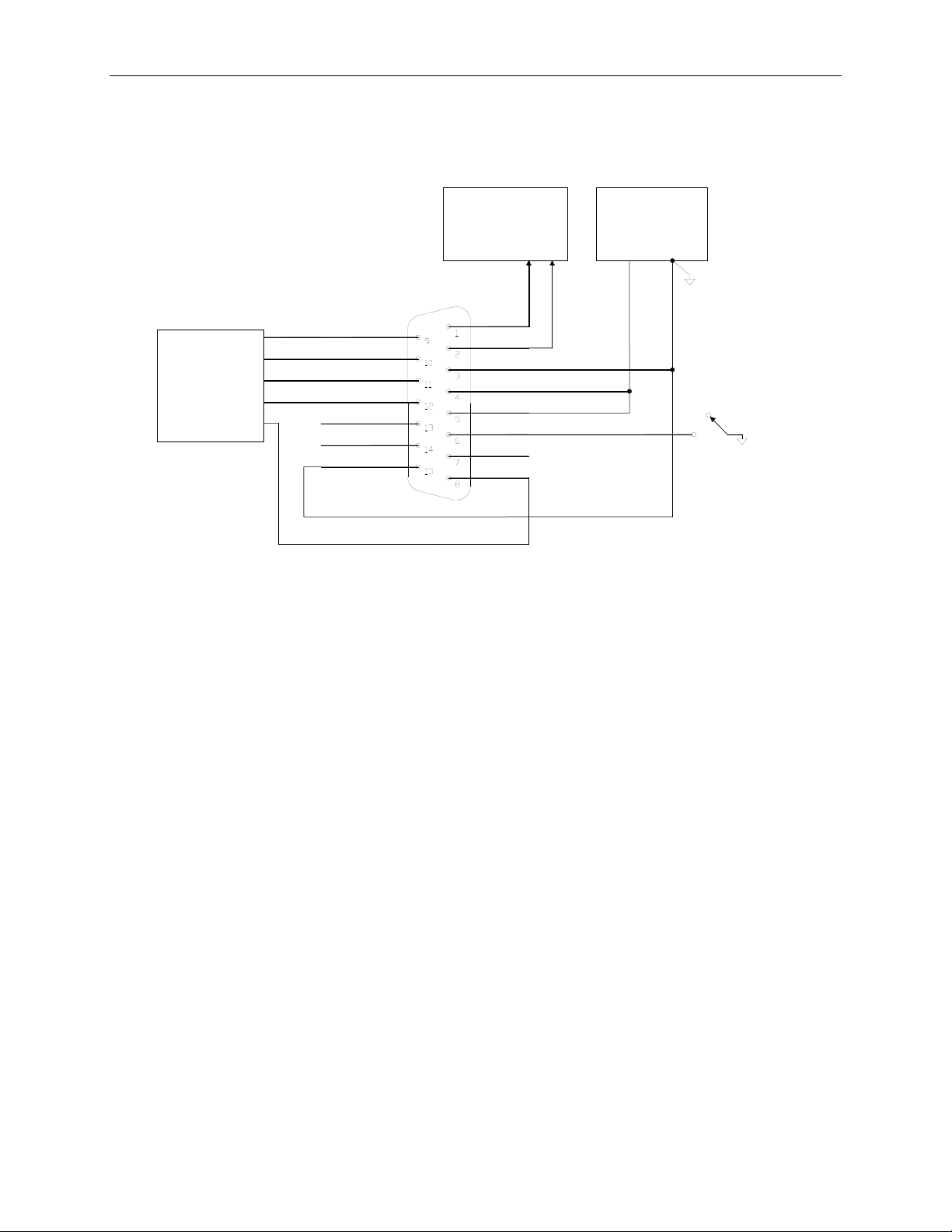
Electrical connections are made to the Model 452 using the 15 pin D-Sub male connector on the
top of the device. Figure 4-1 shows the pin-out of the 15-pin connector and typical connections.
Analog Out -
Analog Out +
Power Common
+15 Volt Supply
+15 Volt Supply
Digital In #1
Digital In #2
Digital Out #1
RS485-A
Power Common
RS485-B
Digital Out Common
Digital Out #4
Digital Out #3
Digital Out #2
Power Supply
Common
+15V
- +
Ozone Concentration
Meter
(0-5 VDC)
or Data Acqusition Device
Status Display
or
PLC
Zero Cal = Closed
Figure 4-1: Electrical Connections
4.3.1 Power Supply
The Model 452 requires a +15 VDC power source capable of supplying 1.5 A. DC power can be
connected through the male DB-15 connector or through the coaxial power jack. The coaxial
power jack is configured so that the ground connection is on the outside (shield) and the +15V
connection is on the center pin.
If power is to be supplied through the DB-15 connector, the positive terminal of the power supply
should be connected to pins 4 and 5 on the 15-pin connector and the common terminal should be
connected to pins 3 and 15.
If an AC Power Adapter is used to provide power, it should be connected to the coaxial power
connector adjacent to the DB-15 connector on the top of the Model 452.
4.3.2 Analog Output
The analog output is a 0-5 volt signal representing the ozone concentration measured by the
sensor. The output is scaled to the concentration range that the sensor has been set to measure.
Check the serial number label on the Model 452 to determine the concentration range.
For best performance, the analog output should be connected to a voltmeter or A/D converter with
a differential input and a minimum input impedance of 2KΩ.

Teledyne API Model 452 Ozone Sensor User Manual, 02852H DCN8478
4-3
4.3.3 Zero Calibration Input
The zero calibration input is located on Digital Input #1. To zero the Model 452, Digital Input #1
should be connected to the power common for at least 1 second. This can be accomplished using a
Normally Open switch or relay.
4.3.4 Status Outputs
The Model 452 has four digital status outputs for indicating error status and when operational
parameters have moved out of normal limits. These outputs are in the form of opto-isolated open-
collector transistors. They can be used to drive status LED’s on a display panel or interface to a
digital device such as a Programmable Logic Controller (PLC).
Figure 4-2 below shows the most common way of connecting the digital outputs to an external
device such as PLC. Note: Most devices, such as PLC’s, have internal provision for limiting the
current that the input will draw from an external device. When connecting to a unit that does not
have this feature, external dropping resistors must be used to limit the current through the
transistor output to 50mA or less.
See Sections 7.2 and 7.2.5 for details on using the Status Outputs for diagnosing sensor and
system-level malfunctions.
Figure 4-2: Digital Output Connections
4.3.5 RS232/485 Interface
The Model 452 features a bi-directional digital serial interface that can be used for sensor control
and data acquisition. The serial port is normally configured at the factory for either RS232 or
RS485 communications. Consult the serial number tag on your device for the port’s configuration.
Figure 4-3 and Figure 4-4 show typical connections. Section 5 provides Communications details.
Controller serial port parameters are as follows:
Baud Rate
9600
Parity
None
Data Bits
8
Stop Bits
1
Teledyne API Model 452 Ozone Sensor User Manual, 02852H DCN8478
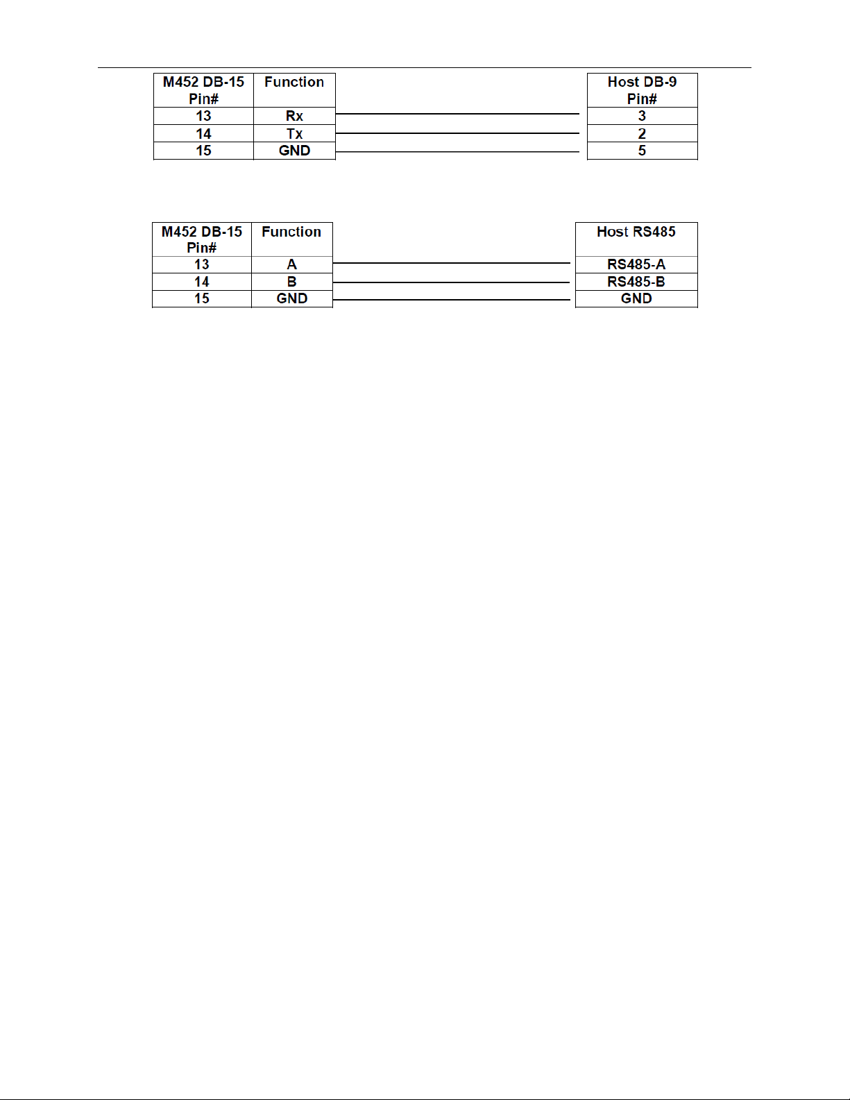
4-4
Figure 4-3. RS232 Connection
Figure 4-4. RS485 Connection
See Section 7.3 in the Sensor and System Troubleshooting section for verifying and configuring
the serial communications connector.
4.4 Gas Connections
Gas connections to the Model 452 are made by using either ¼” compression tube fittings) or ¼”
VCRface seal fittings (fitting option specified at time of purchase). The ¼” compression fittings
can be used with ¼” O.D. Stainless Steel or Teflontubing. The Model 452 is not sensitive to
flow direction; it does not matter which of the two fittings is used as the gas inlet.
To avoid contamination of the optical cell in the Model 452, ensure that all tubing upstream of the
Model 452 is properly cleaned and purged before the Model 452 is installed.
In order to achieve an acceptable response time and to avoid sample degradation, the system
should be set up so that a minimum flow rate of 0.1 SLPM is established through the Model 452.
If long tubing runs are used between the measurement point and the Model 452, then higher flow
rates should be used to avoid sample degredation. Appropriate tests should be conducted to
determine minimum flow requirements.
4.5 Start-Up and Calibration Procedure
1. Verify that the proper electrical connections have been made (See Section 4.3) and apply power to the
Model 452, allowing it to warm up for at least 30 minutes.
2. Purge the Model 452 with zero gas (usually oxygen) at a minimum flow rate of 0.1 SLPM for a
minimum of 5 minutes to purge.
3. Check that the Status Outputs are in their normal states and no errors are indicated (refer to Table 7-1).
4. Close the zero calibration input (See Section 4.3.3) for a minimum of 1 second to perform the automatic
zero calibration.
5. Re-check the Status Outputs to ensure that no errors are indicated.
6. Check the voltage on the analog output (See Section 4.3.2) and verify that it reads 0.000 ±0.010 volts.
The Model 452 is now ready for operation.

Teledyne API Model 452 Ozone Sensor User Manual, 02852H DCN8478
5-1
5 Communications
(If there is a need to troubleshoot, refer to Section 7.3, and to Figure 7-2 or Figure 7-3, according
to which CPU PCA your device is configured with.
5.1.1 RS485/RS232 Commands
All commands are valid for either RS232 or RS485 hardware configuration.
Calibration
Command:
d –
Calibrate Zero
1 byte 1 byte 1 byte
1 byte
<ADDRESS>
<command>
<CR>
<CHKSUM>
ADDRESS must match address of sensor. Range is 0-9 ASCII OR’d w/0x80 (hi bit set) = 0xB0-B9.
Applies to commands ONLY.
CHKSUM is the sum of all characters beginning with the address, ending with <cr>.
Always AND result with 0x7F, so high bit = 0. DO NOT send two’s complement.
Response:
OK<CR><CHKSUM> for an acknowledge
ERR<CR><CHKSUM> for an error
Data Request Command:
a – Send
Data:
1 byte 1 byte 1 byte
1 byte
<ADDRESS>
a
<CR>
<CHKSUM>
Response:
<address>,<Pressure>,<Cell_Temp>,<Meas_mv>,<Ref_mV>,<O3_wt%><CR><CHKSUM>
or:
ERR<CR><CHKSUM> for an error
Address range is ASCII numbers 0-9 (hi bit clear) = (0x30-39). Applies to responses ONLY.
Address Change Command:
i (x) –
Set Address
1 byte 1 byte 1 byte 1 byte 1 byte
0xAA i <New Address> <CR> <CHKSUM>
Address is 0xAA(Hex.) (Note high bit already set.) This is the general call address that all sensors
will receive.
<New Address> is binary value for new address (ie. 0x00 – 0x03)

Teledyne API Model 452 Ozone Sensor User Manual, 02852H DCN8478
5-2
Note:
Control input #2 on M452 (I2C port, bit 1) must be latched (input pulled to ground) prior to
initiating this command. This is required to inform the sensor that it is being addressed. This is the
only command that requires this action. Note that this control input (Pin 7 on the DB15 connector)
has an internal pull-up resistor and so does not require an external pull-up. Input should be released
when acknowledge is received.
Response:
OK<CR><CHKSUM> for an acknowledge
ERR<CR><CHKSUM> for an error
5.1.2 Sample Serial Port Code
The following is some example code in written in Visual Basic that demonstrates how these
commands could be sent to the instrument:
Dim check_sum, address, cmd_code As Byte
address = (&H30 + 0) Or &H80
‘ Address 0, converts to ASCII 0 and sets high
bit to 1‘ can substitute any allowable address
cmd_code = Asc("a")
check_sum = address + cmd_code + 13
‘ Sends ‘a’ command, can substitute ‘d’
command here
check_sum = check_sum And &H7F
‘ Set high bit to 0 for check_sum. This prevents‘
check_sum from being interpreted as an address
for ‘ other sensors on the bus.
Comm1.Output = Chr(address) &
Chr(cmd_code) & _ Chr(13) & Chr(check_sum)
Other manuals for 452
1
Table of contents
Other TELEDYNE API Accessories manuals


