TELEDYNE API OPTI-Sense 5200 User manual

User Manual
OPTI-Sense 5200
with
Fault High, Zero Low, Customer-Supplied Power
© TELEDYNE API (TAPI)
9970 CARROLL CANYON ROAD
SAN DIEGO, CALIFORNIA 92131-1106
USA
Toll-free Phone:
+1 800-324-5190
Phone:
+1 858-657-9800
Fax:
+1 858-657-9816
Email:
api-sales@teledyne.com
Website:
http://www.teledyne-api.com/
Copyright 2022 094900000B DCN8470
Teledyne API 25 March 2022


094900000B DCN8470 Teledyne API OPTI-Sense 5200 i
NOTICE OF COPYRIGHT
© 2022 Teledyne API (TAPI). All rights reserved.
TRADEMARKS
All trademarks, registered trademarks, brand names or product names appearing in
this document are the property of their respective owners and are used herein for
identification purposes only.

ii Teledyne API OPTI-Sense 5200 094900000B DCN8470
SAFETY MESSAGES
Important safety messages are provided throughout this manual for the purpose of
avoiding personal injury or instrument damage. Please read these messages
carefully. Each safety message is associated with a safety alert symbol and is placed
throughout this manual; the safety symbols are also located inside the instrument. It
is imperative that you pay close attention to these messages, the descriptions of
which are as follows:
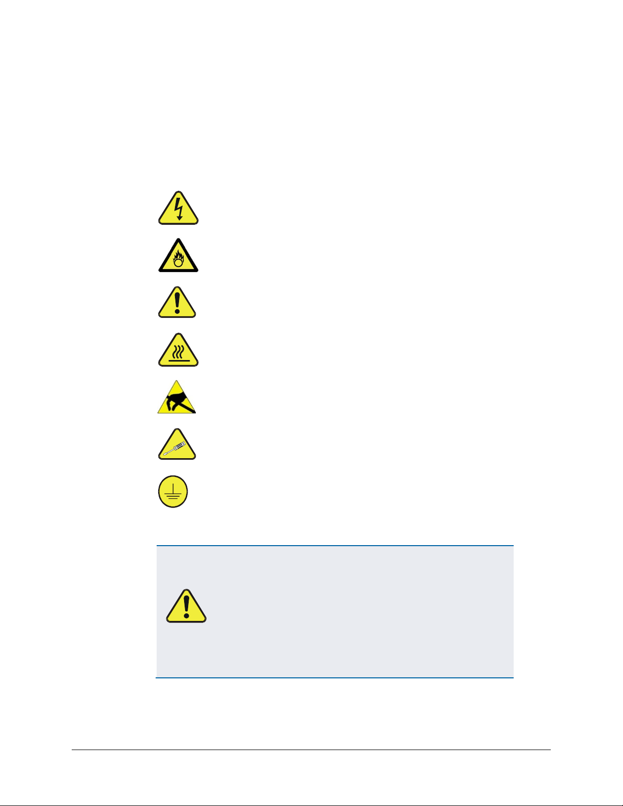
WARNING: Electrical Shock Hazard
HAZARD: Strong oxidizer
GENERAL WARNING/CAUTION: Read the accompanying message
for specific information.
CAUTION: Hot Surface Warning
Do Not Touch: Touching some parts of the instrument without
protection or proper tools could result in damage to the part(s)
and/or the instrument.
Technician Symbol: All operations marked with this symbol are to be
performed by qualified maintenance personnel only.
Electrical Ground: This symbol inside the instrument marks the
central safety grounding point for the instrument.
CAUTION
This product should only be used for the purpose and in the manner
described in this manual. If you use this product in a manner other
than that for which it was intended, unpredictable behavior could
ensue with possible hazardous consequences.
NEVER use any combustible/explosive gas with this product!
For Technical Assistance regarding the use and maintenance of this instrument or
any other Teledyne API product, contact Teledyne API’s Technical Support
Department:
Telephone: +1 800-324-5190
Email: api-techsupport@teledyne.com
or access any of the service options on our website at http://www.teledyne-api.com/
094900000B DCN8470 Teledyne API OPTI-Sense 5200 iii
CONSIGNES DE SÉCURITÉ
Des consignes de sécurité importantes sont fournies tout au long du présent manuel
dans le but d’éviter des blessures corporelles ou d’endommager les instruments.
Veuillez lire attentivement ces consignes. Chaque consigne de sécurité est
représentée par un pictogramme d’alerte de sécurité; ces pictogrammes se retrouvent
dans ce manuel et à l’intérieur des instruments. Les symboles correspondent aux
consignes suivantes :
AVERTISSEMENT : Risque de choc électrique
DANGER : Oxydant puissant
AVERTISSEMENT GÉNÉRAL / MISE EN GARDE : Lire la
consigne complémentaire pour des renseignements
spécifiques
MISE EN GARDE : Surface chaude
Ne pas toucher : Toucher à certaines parties de l’instrument
sans protection ou sans les outils appropriés pourrait entraîner
des dommages aux pièces ou à l’instrument.
Pictogramme « technicien » : Toutes les opérations portant ce
symbole doivent être effectuées uniquement par du personnel
de maintenance qualifié.
Mise à la terre : Ce symbole à l’intérieur de l’instrument
détermine le point central de la mise à la terre sécuritaire de
l’instrument.
MISE EN GARDE
Cet produit doit être utilisé aux fins décrites et de la manière
décrite dans ce manuel. Si vous utilisez cet produit d’une autre
manière que celle pour laquelle il a été prévu, l’instrument
pourrait se comporter de façon imprévisible et entraîner des
conséquences dangereuses.
NE JAMAIS utilizer de gaz explosive ou combustible avec cet
produit!

iv Teledyne API OPTI-Sense 5200 094900000B DCN8470
WARRANTY
WARRANTY POLICY (02024J)
Teledyne API (TAPI), a business unit of Teledyne Instruments, Inc., provides that:
Prior to shipment, TAPI equipment is thoroughly inspected and tested. Should
equipment failure occur, TAPI assures its customers that prompt service and support
will be available. (For the instrument-specific warranty period, please refer to the
“Limited Warranty” section in the Terms and Conditions of Sale on our website at
the following link: http://www.teledyne-api.com/terms_and_conditions.asp).
COVERAGE
After the warranty period and throughout the equipment lifetime, TAPI stands ready
to provide on-site or in-plant service at reasonable rates similar to those of other
manufacturers in the industry. All maintenance and the first level of field
troubleshooting are to be performed by the customer.
NON-TAPI MANUFACTURED EQUIPMENT
Equipment provided but not manufactured by TAPI is warranted and will be
repaired to the extent and according to the current terms and conditions of the
respective equipment manufacturer’s warranty.
PRODUCT RETURN
All units or components returned to Teledyne API should be properly packed for
handling and returned freight prepaid to the nearest designated Service Center. After
the repair, the equipment will be returned, freight prepaid.
The complete Terms and Conditions of Sale can be reviewed at
http://www.teledyne-api.com/terms_and_conditions.asp
CAUTION – Avoid Warranty Invalidation
Failure to comply with proper anti
-Electro-Static Discharge (ESD)
handling and packing instructions and Return Merchandise
Authorization (RMA) procedures when returning parts for repair or
calibration may void your warranty. For anti
-ESD handling and
packi
ng instructions please refer to the manual, Fundamentals of
ESD, PN 04786, in its
“Packing Components for Return to Teledyne
API’s Customer Service”
section. The manual can be downloaded
from our website at
http://www.teledyne-api.com. RMA procedures
can also be found on our website
.

094900000B DCN8470 Teledyne API OPTI-Sense 5200 v
ABOUT THIS MANUAL
Note We recommend that all users read this manual in its entirety
before operating the instrument.
CONVENTIONS USED
In addition to the safety symbols as presented in the Safety Messages page, this
manual provides special notices related to the careful and effective use of the
instrument and related, pertinent information.
ATTENTION COULD DAMAGE INSTRUMENT AND VOID WARRANTY
This special notice provides information to avoid damage
to your instrument and possibly invalidate the warranty.
Important IMPACT ON READINGS OR DATA
Provides information about that which could either affect
accuracy of instrument readings or cause loss of data.
Note Provides information pertinent to the proper care,
operation or maintenance of the instrument or its parts.

vi Teledyne API OPTI-Sense 5200 094900000B DCN8470
TABLE OF CONTENTS
Safety Messages...................................................................................................................................... ii
Warranty.................................................................................................................................................. iv
Table of Contents.................................................................................................................................... vi
List of Figures.......................................................................................................................................... vi
List of Tables........................................................................................................................................... vi
1. INTRODUCTION, CAUTIONS, AND SPECIFICATIONS .........................................................................7
Cautions ............................................................................................................................................7
Specifications ....................................................................................................................................8
Features ............................................................................................................................................8
2. MECHANICAL INSTALLATION................................................................................................................9
3. ELECTRICAL CONNECTIONS ..............................................................................................................11
RS-232 Connector ..........................................................................................................................11
I/O Connector..................................................................................................................................11
Fault DO Specifications .......................................................................................................12
Over-Voltage Protection.......................................................................................................12
4. SYSTEM OPERATION ...........................................................................................................................13
Zeroing the OPTI-Sense .................................................................................................................13
5. INSTRUMENT ERROR CODES.............................................................................................................14
6. TECHNICAL ASSISTANCE....................................................................................................................15
LIST OF FIGURES
Figure 2-1. Mechanical Dimensions.............................................................................................................. 9
Figure 2-2. Inlet (right) and Outlet (left) Connectors................................................................................... 10
LIST OF TABLES
Table 1-1. Specifications............................................................................................................................... 8
Table 3-1. I/O Connector Pinout ................................................................................................................. 11
Table 5-1. Instrument Error Codes ............................................................................................................. 14

094900000B DCN8470 Teledyne API OPTI-Sense 5200 7
1. INTRODUCTION, CAUTIONS, AND SPECIFICATIONS
The Teledyne API Opti-Sense 5200 is a state-of-the-art Non Dispersive InfraRed (NDIR)-
based sensor that is designed to monitor SIF4 (Silicon Tetrafluoride) concentration,
typically at sub-atmospheric pressure.
The OPTI-Sense unit is designed to be mounted vertically. Horizontal mounting is also
acceptable. Two KF16 fittings are provided to effectuate the pneumatic connections.
Electrical connections are on the rear panel of the instrument. Power and control signals
are applied through the DB15 connector. The RS-232 connector should be connected to a
laptop computer if the graphical user interface (GUI) will be used.
The OPTI-Sense 5200 can be used qualitatively three minutes after power up. For accurate
quantitative results, allow the unit to warm up for thirty minutes. The OPTI-Sense should
be allowed to warm up overnight for applications in which low drift is critical. Purge and
zero the instrument after the warm-up period is completed.
CAUTIONS
Please review these instructions carefully to ensure proper installation, operation and care
of the system to minimize the risk of personal injury or product damage due to improper
handling.
HAZARD: Toxic, Corrosive Gas
•SIF4 (Silicon Tetrafluoride) is a toxic, corrosive, nonflammable
gas packaged at pressure up to 1000 psig. It has a sharp
suffocating odor. The gas is colorless but fumes white in moist
air. Hydrolyzes to very corrosive hydrofluoric acid on contact
with moisture. Can cause severe chemical burns if inhaled or
upon skin contact. When entering released area, wear self-
contained breathing apparatus (SCBA). Fully protective suits
are required in large releases.
•Install appropriate safety monitoring equipment wherever SIF4
is used.
•Materials in contact with SIF4 should be suitable for such use.
316L Stainless, Barium Fluoride (BaF2), Teflon™, Chemraz™
are recommended.
WARNING: Electrical Shock Hazard
When performing any maintenance to the unit, make sure all DC
power is disconnected from the unit
CAUTION: Risk of Damage to Instrument
Use only TAPI-recommended spare parts. Substitution parts could
result in damage to the equipment, may create hazardous
conditions, and will void the warranty.

8 Teledyne API OPTI-Sense 5200 094900000B DCN8470
SPECIFICATIONS
Table 1-1. Specifications
Parameter
Description
Measuring Principle
Non Dispersive IR absorption
Application
Measurement of SiF4 Absorbance
Dimensions (W x H x D)
4.72” x 8.66” x 3.15” (120 mm x 220 mm x 80 mm)
Light Source
Infrared light source
Response Time
(time to respond to step
function of SIF4)
< 2 seconds to 90% of step
Reading Update
1 reading/second
Analog scaling/Filter type
1-10 VDC corresponds to (0.0-0.2) units of absorbance,
< 10Watts, factory set
Leak Testing
Vacuum Leak-Tight Cell
Gas Connection
KF16-300 Series stainless steel
Pressure Range
200mT-5000mT
Temperature Range
5 – 45
°
C
Power Input
15 VDC Customer Supplied, 350 mA max during normal
operation
24VDC Customer Supplied
Weight
7 Lbs. (3.17 kg)
Digital Interface
RS-232, with GUI Interface
Software
Embedded (standard) Labview GUI interface
Compliance
CE approved
FEATURES
•Zero by Voltage Command
•Fault Digital Output (DO) indicates instrument errors.
•1-10 Volt Analog Output
•Overvoltage Protection

094900000B DCN8470 Teledyne API OPTI-Sense 5200 9
2. MECHANICAL INSTALLATION
ATTENTION
Ensure adequate space to access connectors and to
remove cover when necessary for servicing.
Ensure adequate clearance to allow free air flow for
cooling, and to avoid high heat-generating equipment.
Sensor dimensions are shown in Figure 2-1.
Figure 2-1. Mechanical Dimensions
10 Teledyne API OPTI-Sense 5200 094900000B DCN8470
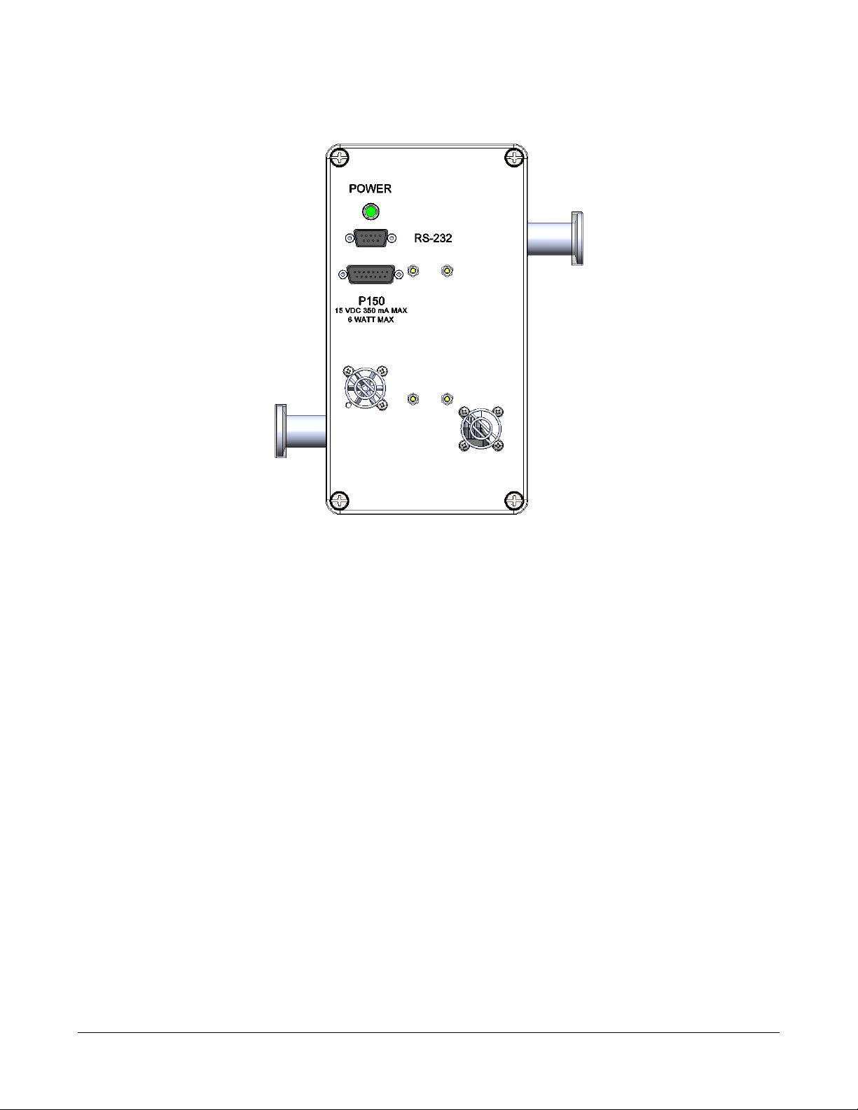
The OPTI-Sense unit is designed to be mounted vertically. Figure 2-2 below shows the
front view of the OPTI-Sense unit, with KF16 inlet connector on the upper right and outlet
connector on the lower left. Horizontal mounting is also acceptable.
Figure 2-2. Inlet (right) and Outlet (left) Connectors
The flow of gas through the unit should be interrupted when there is a possibility of
particulate matter soiling the windows or lodging onto the cell surfaces. Particulate matter
or films deposited onto the cell surfaces will render the measurement inaccurate and the
unit inoperable.
It is strongly recommended that the OPTI-sense unit be periodically purged and zeroed
using reference gas (see Section 4).

094900000B DCN8470 Teledyne API OPTI-Sense 5200 11
3. ELECTRICAL CONNECTIONS
Refer to Figure 2-2 for this section. The status light is a steady green when instrument
power is on. DB9 connector is for RS-232 communications and the DB15 connector is for
the input/outputs (I/O).
Opti-Sense is marked with the appropriate power rating required for the unit to work and
function as designed. Note the supply voltage and current, which are shown on the label.
RS-232 CONNECTOR
If the OPTI-Sense Graphical User Interface (GUI) software is used, the RS-232 output
should be connected to the COM1 port of the computer running the GUI software.
I/O CONNECTOR
Table 3-1, below, shows the I/O connector pinout.
Table 3-1. I/O Connector Pinout
Pin
Connection
Notes
1N/C
2Analog Signal Out
1-10 Volt Range
Scale is factory programmable.
324 VDC Return See note below.
4Digital Input (DI) for Zero Command
Normally high.
Pull low for 200 ms to zero.
5N/C
6N/C
715 VDC Power Input 350 mA max during normal operation.
824 VDC Power Input
9Analog Signal Out Return See note below.
10 Fault Digital Output (DO)
HIGH indicates fault.
LOW indicates no fault.
11 Return for Zero Signal See note below.
12 N/C
13 15 VDC Return See note below.
14 15 VDC Return See note below.
15 Fault DO Return See note below.
Note: Pins 3,9,11,13,14,15 are shorted internally.

12 Teledyne API OPTI-Sense 5200 094900000B DCN8470
FAULT DO SPECIFICATIONS
The Fault DO is configured normally low; the output is high when an error has been
detected.
For most error conditions, the Fault DO will continue to indicate a fault until the unit is
successfully re-zeroed or rebooted. However, some errors are inherently intermittent in
nature, and are cleared automatically when they no longer affect instrument data. For
example, the three minute instrument warm-up period is indicated as an error to allow
detection of accidental power disruption; the Fault DO will indicate no fault when the
warm-up period is over.
•Operating Voltage (Power, pin 8): 24VDC ± 10%
•Output circuit:
oOutput HIGH Voltage: 24 VDC ± 10%, 203 Ωoutput resistance.
oOutput LOW Voltage: 4.9 ± 0.1 VDC, 203 Ωoutput resistance.
OVER-VOLTAGE PROTECTION
Maximum Ratings For DB15 Input Lines
•Forward voltage: 30V
•Reverse voltage: 50V
DB15 output lines are short-circuit protected.

094900000B DCN8470 Teledyne API OPTI-Sense 5200 13
4. SYSTEM OPERATION
The unit is designed to be left powered on at all times. Refer to the zeroing instructions
presented next in Section 4.1.
ZEROING THE OPTI-SENSE
The unit should be fully warmed up and purged of SiF4 before zeroing. Nitrogen, Argon,
Oxygen or vacuum purge are acceptable. Note that the unit will not zero during the three-
minute warm-up time and will report an error if a zeroing request is received during the
warm-up period. (This error can be cleared by zeroing the unit once the warm-up period
is over.) The zero signal command is configured active low; the line must be held low for
at least 200 ms.
•Operating Voltage (HIGH): 24VDC ± 10%
•Operating Voltage (LOW): 0VDC Nominal, 4VDC Max.
Zeroing will take approximately five seconds during normal operation.
Zeroing the OPTI-sense unit is essential to establish a stable baseline reading. TAPI
recommends zeroing the unit as often as possible. In applications were baseline drift is
critical, zeroing before every measurement cycle might be required.
Internal volume of the unit is approximately 40 cc, a minimum of 10 volumes exchanges
is recommended before zeroing the OPTI-sense. Please note that internal volume of tubing
connected to the unit should be considered when calculating purge time and flow rate.
Note that the OPTI-Sense has analog output range 1-10 volt. After the sensor is zeroed,
the analog output will read one volt.

14 Teledyne API OPTI-Sense 5200 094900000B DCN8470
5. INSTRUMENT ERROR CODES
Table 5-1 shows the instrument error codes, their causes, and corrective action.
Table 5-1. Instrument Error Codes
Error
Code
Cause Corrective Action
2
Too much light - out of design range. The
instrument may have been zeroed while
SiF4 was present.
Purge and zero the instrument.
3 No light detected.
Purge and zero the instrument. If error persists after
zeroing:
•Do not open the unit without prior permission
from TAPI.
•Contact TAPI immediately for service
instructions. It may be possible to repair your
unit in situ.
•If you do remove the unit, check the KF16
ports for powder contamination. Powder
contamination indicates presence of particulate
matter or a deposited film. Make sure that
provisions are in place to prevent particulate
matter or film deposition onto the surfaces of
the absorption cell.
4
Too much light - signal cannot be
measured. The instrument may have been
zeroed while SiF4 was present.
Purge and zero the instrument.
5 Instrument warming up.
Will clear automatically three minutes after the
instrument boots up.
6
A zeroing request was invalid because the
instrument was warming up. The instrument
did not honor the zeroing request.
Wait for the three minute warm-up period to complete,
then re-zero the instrument.
7
Insufficient light.
Same as for Error Code 3.
8 Timing error.
Purge and zero the instrument. Contact TAPI if the
problem occurs repeatedly.
9 Missed reading.
Purge and zero the instrument. Contact TAPI if the
problem occurs repeatedly.

094900000B DCN8470 Teledyne API OPTI-Sense 5200 15
6. TECHNICAL ASSISTANCE
Please contact our Technical Support department for any technical assistance needed:
Teledyne API Technical Support
9970 Carroll Canyon Road
San Diego, California 92131-1106 USA
Toll-free Phone: +1 800-324-5190
Phone: +1 858-657-9800
Fax:
+1 858-657-9816
Email: api-techsupport@teledyne.com
Website:
http://www.teledyne-api.com/
Table of contents
Other TELEDYNE API Accessories manuals


