Telegesis TG-ETRXn-UG-01-104 User manual

Telegesis (UK) Limited
TG-ETRXn-UG-01-104
1
User Guide
1.04
ETRX1 and ETRX2
Telegesis
©2008 Telegesis (UK) Ltd ETRXn User Guide (Rev 1.04)
TG-ETRXn-UG-01-104
ETRXn WIRELESS MESH NETWORKING MODULES
Firmware R2xx User Guide

Telegesis (UK) Limited
TG-ETRXn-UG-01-103
2
User Guide
1.04
ETRX1 and ETRX2
©2008 Telegesis (UK) Ltd ETRXn User Guide (Rev 1.04)
Table of Contents
1INTRODUCTION.....................................................................................................3
2GETTING STARTED ..............................................................................................3
3NETWORK MANAGEMENT...................................................................................9
3.1 Overview.................................................................................................................9
3.2 Device Types........................................................................................................10
3.3 Network Establishment and Maintenance .............................................................11
3.3.1 AT+EN –Establish Network..................................................................................11
3.3.2 AT+DASSL –Disassociate Local Node.................................................................12
3.3.3 AT+DASSR –Disassociate remote device from PAN............................................12
3.3.4 AT+JN –Join Network ..........................................................................................12
3.3.5 AT+PANSCAN –Scan for all available channels ..................................................12
3.3.6 AT+JPAN:cc,pppp - Join specific PAN..................................................................12
3.3.7 AT+N –Display network parameters.....................................................................12
3.3.8 AT+ESCAN –Scan the energy of all channels......................................................12
3.3.9 AT+SN –Scan network for other nodes................................................................12
3.3.10 AT+REMSN –Scan for remote device‟s direct neighbours....................................13
3.3.11 AT+LINKCHECK - Check link parameters with a neighbour..................................13
3.3.12 AT+PING - Indicate presence in the network ........................................................13
3.3.13 ATS & ATSREM –Read and write S-registers......................................................13
3.4 Managing a Network.............................................................................................13
3.5 Maintaining a Network...........................................................................................13
4DATA TRANSMISSION........................................................................................14
4.1 Overview...............................................................................................................14
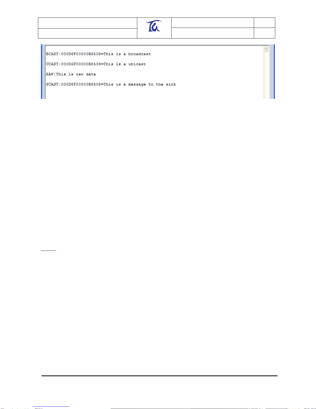
4.2 Broadcasts............................................................................................................14
4.3 Raw data...............................................................................................................15
4.4 Unicasts................................................................................................................15
4.5 S-Casts.................................................................................................................15
4.6 Channels...............................................................................................................16
5S-REGISTERS......................................................................................................17
5.1 Overview...............................................................................................................17
5.2 Radio Setup (S00-S03).........................................................................................17
5.3 Module Setup (S04-S0A) ......................................................................................18
5.4 I/O-related registers (S0B-S14).............................................................................19
5.5 Event Management (S15-S28)..............................................................................21
5.5.1 Interrupts...............................................................................................................21
5.5.2 Timers...................................................................................................................22
5.5.3 Power Management (S29-S2A).............................................................................22
5.5.4 Functionality text (S2B-S2C).................................................................................23
5.6 Device-specific registers (S2D-S35)......................................................................23
6SPECIALISED I/O ................................................................................................24
6.1 Tone Generation at Pin I/O3 .................................................................................24
6.1.1 ETRX1 Settings ....................................................................................................24
6.1.2 ETRX2 Settings ....................................................................................................25
7REVIVING AN UNRESPONSIVE MODULE .........................................................26
8SECURITY............................................................................................................26

Telegesis (UK) Limited
TG-ETRXn-UG-01-103
3
User Guide
1.04
ETRX1 and ETRX2
©2008 Telegesis (UK) Ltd ETRXn User Guide (Rev 1.04)
9NETWORK COMMISSIONING.............................................................................27
10 APPLICATION EXAMPLES .................................................................................28
10.1 Simple Temperature Sensor .................................................................................28
10.2 Switch Application.................................................................................................28
10.3 Serial Port Replacement .......................................................................................29
10.4 Using a Host Microcontroller .................................................................................29
10.5 Custom Functionality.............................................................................................29
10.6 Developing Your Own Firmware............................................................................29
11 BUILT-IN FUNCTIONALITY.................................................................................30
12 GLOSSARY..........................................................................................................34
13 MODULE PINOUTS..............................................................................................34
14 TRADEMARKS ....................................................................................................36
15 DISCLAIMER........................................................................................................36
16 CONTACT INFORMATION ..................................................................................36
17 REFERENCES .....................................................................................................37
1 Introduction
This document gives an introduction on how to set up and operate the Telegesis ETRXn ZigBee®
modules with firmware revisions R2xx. The examples in this document assume that you are using
the ETRXnDVKx Development Kit. However most of the features described can also be evaluated
using any custom hardware based on the ETRX1 or ETRX2 modules.
Towards the end of this document a number of possible application scenarios are listed in order to
show the versatility of the ETRXn modules.
Some of the details will vary from one firmware version to another; this guide was written when
R212 was current.
Do not use this guide if you are using R1xx firmware as the AT Command set is different. Please
check the Telegesis website www.telegesis.com regularly for updates.
2 Getting Started
The ETRXn sends and receives commands and data from its host computer through a UART as
ASCII strings. You can use your own application software, a tool such as HyperTerminal, or our
own Telegesis Terminal which is a free download from our website. To use it, first install .NET
Framework Version 1.1 Redistributable Package from Microsoft. This is currently available at
www.microsoft.com/downloads/details.aspx?familyid=262D25E3-F589-4842-8157-
034D1E7CF3A3&displaylang=en
Note that Version 2 or later is not sufficient as it supplements Version 1.1 but does not replace it.
Then download Telegesis Terminal from our website at www.telegesis.com/ZigBee/Dsoftware.htm.
Telegesis (UK) Limited
TG-ETRXn-UG-01-103
4
User Guide
1.04
ETRX1 and ETRX2
©2008 Telegesis (UK) Ltd ETRXn User Guide (Rev 1.04)
Note: Telegesis Terminal is not a GUI that interprets the AT commands and sends instructions to
the ETRX2 in another format. It does not alter the AT commands in any way –the ETRX2
receives them exactly as described here and in the AT Command Manual. Likewise, if you are
writing your own terminal application, it should send and receive data as formatted in our manuals.
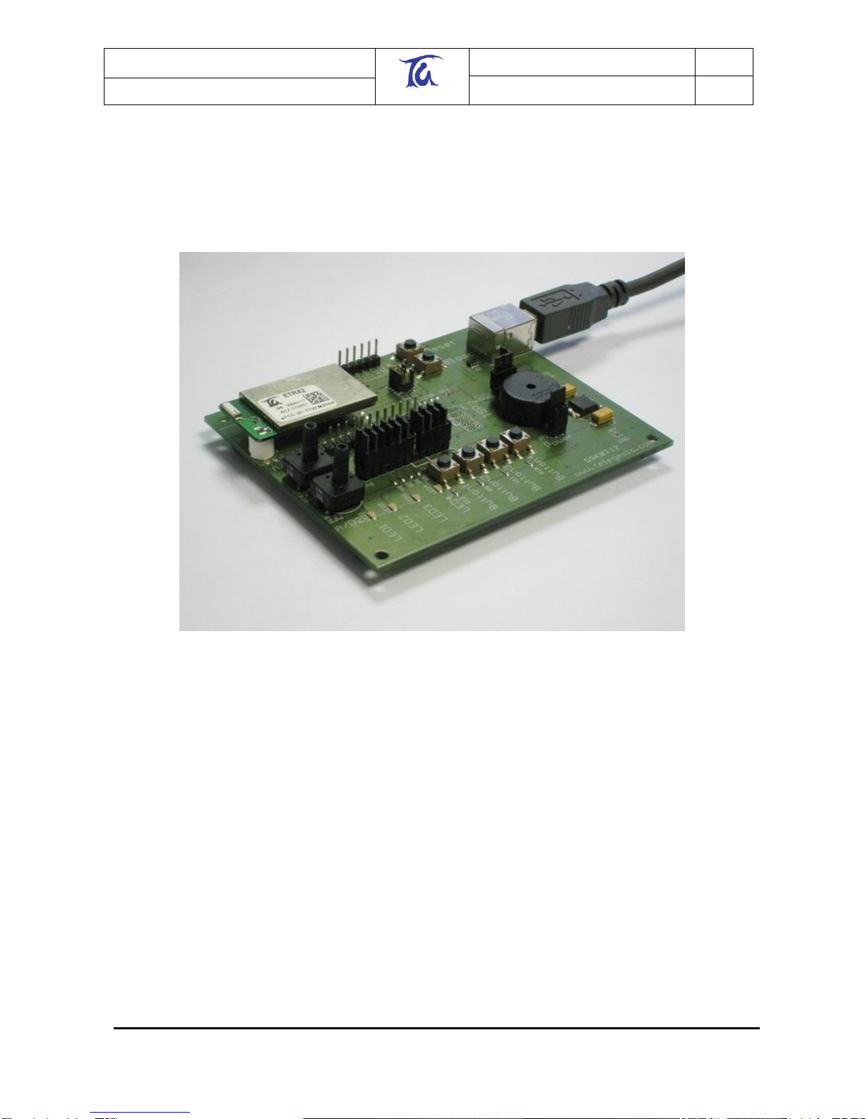
In order to get started, plug an ETRXn module on to each development board which forms part of
your set-up and connect at least one development board to a PC using the serial or USB cable
provided.
Figure 1. Development board with module mounted
Power up all of the development kits and module carrier boards (MCBs) and start the Telegesis
Terminal application on the PC. You need to know which of your computer‟s COM ports is
connected to the development board, which may not be obvious if you are using a USB-to-serial
adaptor, for example. To check, open your PC‟s Device Manager; there are several ways in
Windows XP, but the simplest is to right-click on “My Computer” and select “Manage”, then
“Device Manager”. In this example there are two USB-to-serial adaptors in COM3 and COM4 and
a USB stick in COM5:

Telegesis (UK) Limited
TG-ETRXn-UG-01-103
5
User Guide
1.04
ETRX1 and ETRX2
©2008 Telegesis (UK) Ltd ETRXn User Guide (Rev 1.04)
Figure 2. Windows Device Manager
The connection should be set up using the default values as shown in Figure 3. By default the
module uses a bit-rate of 19200bps, no parity, 8 data bits, 1 stop bit and no flow control. Optionally
XON/XOFF as well as hardware flow control is supported. (See section 10 for more detail).
Pressing the “Connect” button establishes the connection to the ETRXn module on the
development board.
Figure 3. Setup of the Serial Connection
The module will accept commands starting with the “AT” prefix after it has booted up successfully.
Booting up can take 1-2 seconds and on completion the module will prompt “OK”.
Entering the “ATI” command into the terminal window, followed by <Enter>, will cause the module
to display its manufacturing information. Alternatively the “Info” button in the “Module Control”
section can be pressed, causing the “ATI” command to be sent to the local module. After executing
a command the module will prompt “OK” or an error code as explained in the AT command
dictionary.
Telegesis (UK) Limited
TG-ETRXn-UG-01-103
6
User Guide
1.04
ETRX1 and ETRX2
©2008 Telegesis (UK) Ltd ETRXn User Guide (Rev 1.04)
In order to communicate with other modules a module must be part of a PAN (Personal Area
Network). To find out about the status of the local module simply issue the “AT+N” command and
this will show you the module‟s network status. If the module is not part of a PAN (response
“+N:none”) it can be instructed to join an existing PAN using the “AT+JN” command, or to start a
new PAN for other units to participate in using the “AT+EN” command. In order to exchange
messages all units need to be on the same PAN, i.e. have the same channel and the same PAN
ID. The response “+N:cc,pppp” displays the channel number (cc) and the PAN ID (pppp) of the
current PAN. If you have a module which is part of a separate PAN simply use the “AT+DASSL”
command to leave the current PAN and try joining the correct PAN using the “AT+JN” command.
Network establishment and maintenance is described in more detail in Section 3.3.
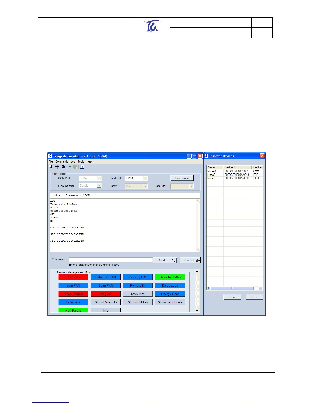
In order to find other nodes which are part of the same PAN press the “Scan Pan” button which
sends the “AT+SN” command to the local module. (Your terminal software may expect a
parameter after the command, namely the number of hops to interrogate. Just type a suitable two-
digit number e.g. “08”). The module will now transmit a request to all the modules within eight
hops asking them to identify themselves. When modules are found the “Discover Devices” window
will pop up (if not already open) and display a list of all of the modules which have reported in. See
Figure 4.
Figure 4. Results of a network search
In this example three additional modules were detected: one ZigBee Coordinator (COO), one
ZigBee Router (FFD) and one Sleepy End Device (SED). For an explanation of the device types
see Section 3.2.
Telegesis (UK) Limited
TG-ETRXn-UG-01-103
7
User Guide
1.04
ETRX1 and ETRX2
©2008 Telegesis (UK) Ltd ETRXn User Guide (Rev 1.04)
An alternative way to search the PAN for other modules is to hit the “Configure” button. As well as
scanning the PAN as before, it adds extra buttons to control the buzzer and LEDs on each remote
module.
Depending on the previous usage of your development kit, units may either immediately
communicate with each other on the same PAN, or they may be off-line. If the unit connected to
your PC does not report that it has joined a PAN within a few seconds of power-up, a suitable
procedure would be:
1. issue the command AT+JN to join any existing PAN or
2. issue the command AT+PANSCAN followed by AT+JPAN:<channel>,<PAN ID> to find and
join a specific PAN or
3. Wait for the module to automatically join a PAN as described in section 3.1.
4. If the steps above do not reveal an existing PAN, issue the command AT+EN to initiate a
new PAN. Others units searching for a PAN will then attach to it within a few minutes, and
be reported with a “NEWNODE:<EUI64>” prompt.
A common problem occurs when the user establishes a PAN and waits for the other devices to join
it … and waits … and waits. This usually means the the other devices are already in a PAN of
their own (set up when they were last used), and as long as they can communicate amongst
themselves they will ignore the new network. If you disassociate the local node and use the
AT+PANSCAN or AT+JN command, this will reveal the pre-existing PAN; you can join it and then
either carry on using it or disassociate the remote nodes and start afresh.
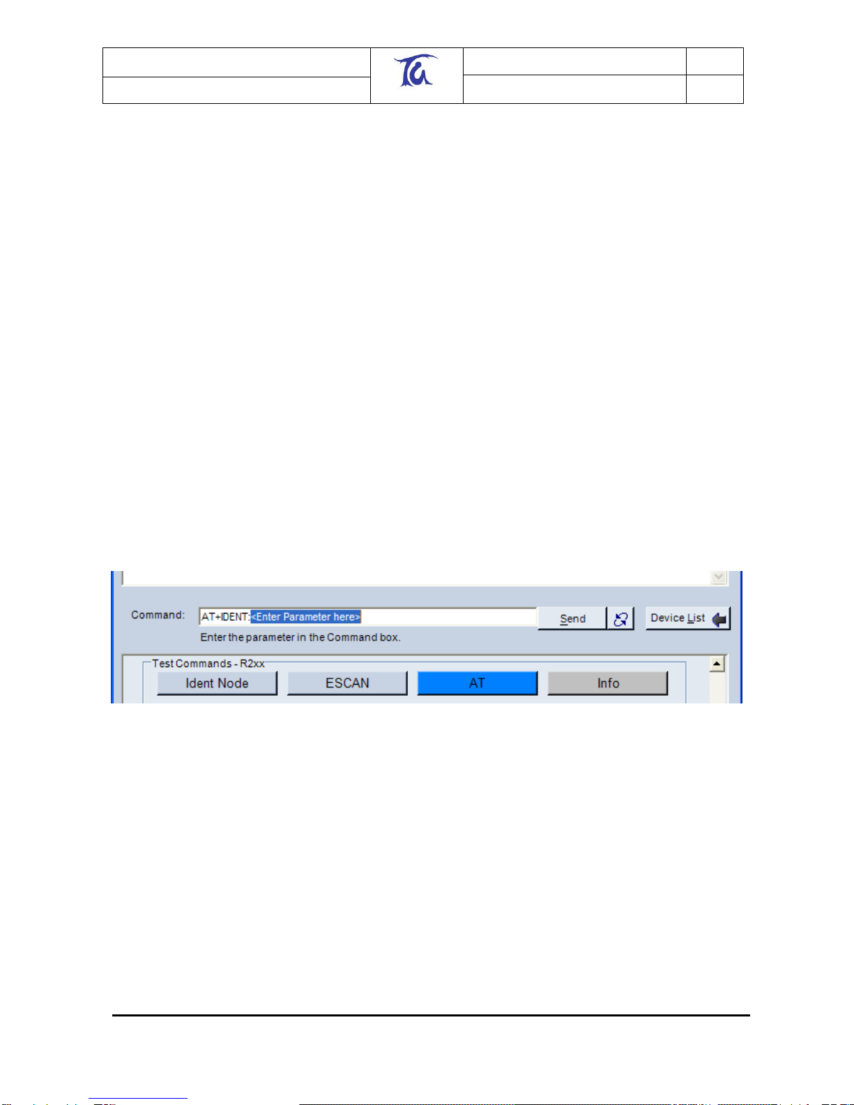
In order to find out which of the detected modules is which, press the “Ident Node” button in the
“Test Commands” section of the buttons. This command requires an additional parameter,
therefore instead of sending a command straight to the local node the command is displayed in the
command bar with the text “<Enter Parameter here>” highlighted.
Figure 5. Entering parameters
Now, double click on any entry in the “Discover Devices” window and the serial number of the
selected device will be added as a parameter. The command is executed by either pressing
“Enter”, or by clicking the “Send” button.
When executing this command the local module will send a request to the module with the
specified serial number asking it to identify itself. A module can identify itself by playing a tune on
a buzzer which is connected to I/O3. If you are using the devkit and you do not hear a tune check
that the jumper for I/O3 is set so that I/O3 is an output (factory default); on the MCBs the buzzer is
directly connected to I/O3.
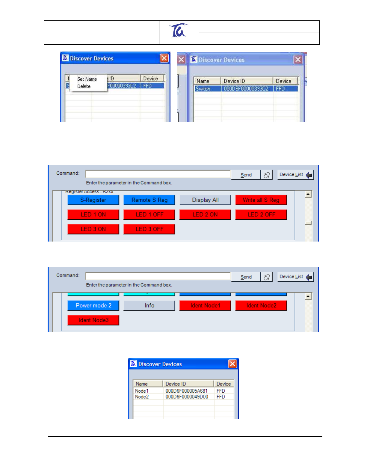
Having identified which module is which you can now give each module a name using the
Telegesis Terminal software. To do this, right click on the entry in the “Discover Devices” window
(as shown in Figure 6) and enter the name when prompted to do so. Please note that this name is
not written to the module itself, it only represents a temporary name which can be used to simplify
the evaluation process using the Telegesis Terminal software.
Telegesis (UK) Limited
TG-ETRXn-UG-01-103
8
User Guide
1.04
ETRX1 and ETRX2
©2008 Telegesis (UK) Ltd ETRXn User Guide (Rev 1.04)
Figure 6: Device Naming
If you have used the “Configure” button, your button window will resemble Figure 7 and Figure 8
and the device table Figure 9.
Figure 7. "LED" buttons after a “Configure” operation
Figure 8. "IDENT" buttons after a “Configure” operation
Figure 9. Device table after a “Configure” operation

Telegesis (UK) Limited
TG-ETRXn-UG-01-103
9
User Guide
1.04
ETRX1 and ETRX2
©2008 Telegesis (UK) Ltd ETRXn User Guide (Rev 1.04)
After identifying all of the devices in the network we can also send messages to any devices within
range. In order to send a broadcast message to all of the devices, use the “AT+BCAST:”
command followed by the number of hops you want the broadcast to travel followed by the text you
wish to broadcast, or simply press the “Broadcast Button” and enter parameters into the Command
line. (E.g. “AT+BCAST:01,Hello World”)
In order for the remote nodes to display received data they will need to be connected to a PC‟s
serial port.
It is also possible to send data to an individual node using a Unicast. To send a Unicast press the
“Unicast” button and then double click on the entry of the recipient in the “Discover Devices”
window and enter the data you wish to transmit preceded by an equal sign. If you do not know the
syntax of a command, hold the mouse pointer over the respective button and the tool tip text will
display the format of the command as shown in Figure 10.
Figure 10. Tool tip texts
So far we have set up all of the hardware required for a meshing network, identified and named the
individual modules using the Telegesis Terminal Software and actioned a few simple commands in
order to learn the functionality of the AT-Style command line interface.
This level of complexity may well be all you need for your application. Before we now look at
additional commands we need to introduce some more theoretical information about wireless mesh
networks.
3 Network Management
3.1 Overview
A ZigBee®(-like) network is formed from the inside out. This means that a device which is
instructed to start a network becomes a so-called coordinator and scans all available radio
channels, picks the one with the least traffic and generates a random PAN ID in order to start a
network; other nodes can then join in.

Telegesis (UK) Limited
TG-ETRXn-UG-01-103
10
User Guide
1.04
ETRX1 and ETRX2
©2008 Telegesis (UK) Ltd ETRXn User Guide (Rev 1.04)
Another scenario is that a node scans for an available network to join, and if no network is found
the node can choose to become a coordinator and start its own network as described above.
Remote nodes are then capable of finding this newly established network and joining it. As more
and more remote nodes join, the network grows from the inside out. If the network is spread over
a wide area, a new node may be out of range of the coordinator and will join the PAN via another
node, which will act as a router. Messages may then pass across the network in more than one
“hop”.
The Telegesis AT command driven software supports point-to-point messages travelling up to six
hops and broadcast messages travelling up to ten hops through the network.
In the examples of Section 3.3, the commands used to establish and maintain a network are
described. For a list of all available commands please refer to the AT-Command dictionary
document.
3.2 Device Types
A ZigBee®network can consist of three different device types:
ZigBee Coordinator (ZC)
ZigBee Router (ZR)
ZigBee End Device (ZED)
ZigBee Coordinators, Routers and End Devices were formerly known as Coordinators, Full
Function Devices and Reduced Function Devices. ZigBee End Devices can be further classified
as Sleepy End Devices (SED) and Mobile End Devices (MED).
A ZigBee Router can route messages between ZigBee®devices, whereas a ZigBee End Device
does not provide any routing capabilities. The primary difference between the two is that a ZR
needs to constantly be awake in order to fulfil its routing responsibilities, whereas a ZED can spend
its life in sleep mode as it has no routing responsibilities.
ZRs consequently consume more power than ZEDs, therefore you must evaluate which type of
device will suit your application best. See Section 10 for a list of example scenarios.
A Coordinator is effectively a Router which has started the network. Each network must have only
one coordinator node. With the meshing stack of EmberZNet a mesh will continue to function even
if the coordinator leaves the PAN.
A ZigBee End Device has no routing responsibilities and joins the network via a ZigBee Router (its
“parent”). The parent will buffer up incoming messages for its “child” while it is asleep. The child
should poll regularly to check if there are any new messages pending on the parent device to
prevent loss of messages due to buffer overflow. The parent will also act as a relay point for its
childrens' outgoing messages. For example when a child wants to send a broadcast it sends the
data to its parent and the parent in turn will initiate the broadcast.
There are two different types of ZigBee End Devices defined in EmberZNet:
sleepy end device
mobile end device
The sleepy end device will remain in its parent‟s child list permanently (or until the parent is reset
or leaves the network by itself). This implies that the sleepy end device should not physically move
away from its parent and join a new parent, as it will still block a child entry at its previous parent.
A mobile sleepy end device will time out and be erased from the parent‟s child table if it does not
poll its parent within 3 seconds. When a mobile end device cannot find its parent it assumes that it
has moved and will search for a new parent. A device need not be defined as “mobile” merely if it

Telegesis (UK) Limited
TG-ETRXn-UG-01-103
11
User Guide
1.04
ETRX1 and ETRX2
©2008 Telegesis (UK) Ltd ETRXn User Guide (Rev 1.04)
changes its physical location; the key point is it that moves enough within the area covered by a
PAN to need a new parent. If, for example, the PAN only contains one parent and a number of
end devices (a “star” topology), there is no point in defining the ZEDs as mobile since there is no
other parent to adopt them.
In the Telegesis AT command software each routing device can have up to eight sleepy end
devices and up to eight mobile end devices.
A module becomes a coordinator by issuing AT+EN as described above. Whether a device joins
as a ZigBee Router or sleepy/mobile end device is determined by the settings in S06 at the instant
the device joins a PAN, so if you are currently joined as a router and want to become a mobile end
device you have to complete the following steps:
1. Leave the network
2. Change S06 accordingly
3. Re-join the network
An end device will always keep its radio switched off (unless used) and therefore consume less
power than a router, even when fully awake.
In power levels 0 to 2 (see section 5) by default an end device will poll its parent for new data once
every second via the built-in functionality. This timing can be altered or disabled altogether if
required. Polling takes less than 10ms, so the battery life of end devices can be maximised. Up to
three incoming broadcasts are stored on each parent until overwritten by new broadcasts.
Unicasts can only be stored for as long as the timeout period on the sending device, so when
expecting to receive unicasts you are required to poll at least in the default interval of once every
second.
When sending a unicast from an end device the unit will keep polling for the acknowledgement
until it has been received or the transmission has timed out regardless of the configured polling
interval.
3.3 Network Establishment and Maintenance
3.3.1 AT+EN –Establish Network
When the local module is not a member of a network, it can initiate a new one and become that
network‟s coordinator. Issuing the “AT+EN” command scans all the available channels, looking for
the one with the lowest energy level; it then generates a random PAN ID, checks to ensure that a
network with this PAN ID does not already exist and then starts a PAN. A unit on which this
command has been executed automatically becomes the network‟s coordinator and remains the
coordinator until it leaves the network using “AT+DASSL”. Neighbouring nodes can now join this
newly established network using “AT+JN”.
[If you are familiar with EmberNet R1** meshing technology and preferred the old way of picking
the channel and PAN ID manually, there is no need to worry as this is still possible. S-Register 00
holds a 16-bit word in which each bit represents one of the available 802.15.4 channels 11-26.
Setting a bit to 1 enables a channel, and setting a bit to 0 disables it. It is therefore possible to
mask out channels which are known to be noisy in the chosen application environment. Setting
the mask to fifteen 0s and a single 1 will force operation on one radio channel. (The mask can also
be used to block ETRXn transmission on channels that you wish to reserve for other systems that
may not yet be in operation.)]
Register S01 allows you to select a preferred PAN ID. By default this register is set to FFFF, which
causes the coordinator to pick a random PAN ID when establishing a PAN. Any number between
0000 and 3FFF will cause the unit to start a PAN with the specified PAN ID unless that particular

Telegesis (UK) Limited
TG-ETRXn-UG-01-103
12
User Guide
1.04
ETRX1 and ETRX2
©2008 Telegesis (UK) Ltd ETRXn User Guide (Rev 1.04)
PAN ID is used by another network. In this case, a randomly generated number is allocated
instead.
3.3.2 AT+DASSL –Disassociate Local Node
To check for the presence of PANs (AT+PANSCAN), measure the signal energy in the radio
channels (AT+ESCAN), or join a different network, a node must first disassociate itself from its
current network using the “AT+DASSL” command.
3.3.3 AT+DASSR –Disassociate remote device from PAN
To move a node from one PAN to another, it must first be disassociated. This may be necessary
when it is intended to swap a coordinator unit for another (which will initiate a new PAN).
3.3.4 AT+JN –Join Network
The node will scan all channels for a PAN which allows units to join. Once it has found such a
network the node will join in. This is a very convenient way of joining a network; it does not,
however, give the local node a choice of which network to join if there is more than one network
available.
3.3.5 AT+PANSCAN –Scan for all available channels
“AT+PANSCAN” will produce a list of all available channels from which you can manually choose
the one you wish the unit to join. To perform this you need to use the “AT+JPAN” command.
3.3.6 AT+JPAN:cc,pppp - Join specific PAN
cc is the channel number and pppp is the PAN ID of the PAN which is to be joined. There are also
a number of auxiliary commands, shown below.
3.3.7 AT+N –Display network parameters
“AT+N” reports the type of the local node (see section 3.3), the channel number and PAN ID, and
the transmitter power.
3.3.8 AT+ESCAN –Scan the energy of all channels
”AT+ESCAN” scans all channels which are not masked out in register S00 and displays their
energy levels.
3.3.9 AT+SN –Scan network for other nodes
This functionality has been extended so that it is now possible to specify the number of hops the
search should cover (1 to 6). This combines the AT+SN and AT+SNEIGHBOURS command of
R1xx into a single command. Optionally the RSSI and LQI readings between the remote device
and the local device can be displayed if bit 6 of register S06 is set as described in section 5.

Telegesis (UK) Limited
TG-ETRXn-UG-01-103
13
User Guide
1.04
ETRX1 and ETRX2
©2008 Telegesis (UK) Ltd ETRXn User Guide (Rev 1.04)
3.3.10 AT+REMSN –Scan for remote device’s direct neighbours
This returns the direct neighbours of a remote device. Optionally the RSSI and LQI readings
between the remote device and the reporting device can be displayed if bit 6 of register S06 is set
as described in section 5.
3.3.11 AT+LINKCHECK - Check link parameters with a neighbour
This gives you the opportunity to check the RSSI and LQI between the local node and a direct
neighbour without the delays inflicted by AT+SN.
3.3.12 AT+PING - Indicate presence in the network
A remote device can indicate its presence in the network by pinging out its ID when instructed by
the “AT+PING” command. All devices receiving the ping that have bit 6 of register S06 set will
display the RSSI and LQI.
3.3.13 ATS & ATSREM –Read and write S-registers
“ATSxx?” returns the contents of local register xx, while “ATSxx=XXXX” sets it to XXXX. The
corresponding syntax for register xx of remote node <EUI64> is “ATSREMxx:<EUI64>?” and
“ATSREMxx:<EUI64>=XXXX”. The S-registers control the module‟s functions and I/O; for
example “ATS0F=0000” clears all the bits of the output register 0F, and for a module on a Devkit
board lights up all the LEDs. “ATSxxy” or “ATSREMxxy” accesses bit y alone of register xx.
3.4 Managing a Network
Previously we used the AT+SN command to scan the network for other nodes. Having found
them, we were able to interact with those nodes by referencing them using their unique serial
number.
Nodes can also be asked to disassociate from the coordinator both locally as well as remotely by
the coordinator itself, using the “AT+DASSL” and “AT+DASSR” commands respectively.
By default, remote nodes are automatically permitted to join a PAN, but various bits in register S06
can set a secure restricted joining mode or can close a PAN to all new members.
All these commands may seem a lot to memorise at this point, but their use will become more
obvious once you have looked at the examples in Section 10.
3.5 Maintaining a Network
A network is self-healing, which means that if a certain path between two nodes breaks, the mesh
will find a new path to make communication possible, unless one of the nodes has simply gone out
of range of the entire network.
Each node periodically checks it has not lost its neighbouring devices; if it has lost connectivity to
its PAN, it leaves the network (default function of Timer 4). A module that is not part of a network
periodically searches for one that it can join (default function of Timer 3); hence a node may
temporarily drop out of the net and come back in again, possibly via a different parent node if it has
moved. If there is a risk that a node may drop out and be re-captured by a different PAN, security
modes should be invoked (see section 8).

Telegesis (UK) Limited
TG-ETRXn-UG-01-103
14
User Guide
1.04
ETRX1 and ETRX2
©2008 Telegesis (UK) Ltd ETRXn User Guide (Rev 1.04)
Once the network has been established you may wish to keep this network private so other nodes
do not interfere with it. The first method is to prevent more nodes from joining (register S06, bit B),
the second is to only permit secured joining from the beginning (see section 8 for security).
Attempts to achieve privacy by setting radio channel masks or preferred PAN IDs may not be
reliable since the network‟s environment cannot be predicted. This is discussed more fully in
section 8.
4 Data Transmission
4.1 Overview
The purpose of a network is - of course - to send data between nodes. The data (formatted as
successive bytes) can be of predefined or undefined length, or may be single 16-bit words
controlling the ETRXn‟s I/O ports. It can be sent to a single node, or broadcast across the network.
ZigBee®has been designed for control and automation applications, therefore the maximum
payload for any message type mentioned in this section is 65 bytes, which reflects the small and
efficient messaging structures of ZigBee®(the exception is a packet of raw data sent by the
AT+RDATAB command, which can hold 114 bytes).
The strength of a meshed network compared to traditional point-to-point radio systems is that data
can be sent between nodes which are out of range of one another. The packets containing the
data dynamically route through the network finding the best possible path. In doing so the mesh
network can dynamically react to a changing RF environment and self-heal broken links, given that
an alternative route from the source to the destination of the data is present.
Due to the potential presence of alternative routes, packets may not arrive at their destination in
the order they have been sent and also the timing of messages may vary.
The worst case delay for data to be transmitted from one node to a direct neighbour (one hop) is
100 milliseconds. In addition, it may take as much as 100 milliseconds for an acknowledgement to
find its way back. When sending data it is assumed that the user (or the application) doesn‟t want
to have messages in transit for more than 3.6 seconds, which leads to a limitation of the maximum
possible number of hops. In practise a node not having received an acknowledgement for 1.2
seconds will issue a retransmit and after three unsuccessful transmissions the message delivery
will be timed out and reported unsuccessful. This leads to a worst case limitation of 6 hops since
the worst case delay between each hop is 100ms, so we are looking at 600ms for the signal to
reach its destination and another 600ms for the acknowledgement to find its way back. As a result
of this when planning an application using wireless meshing networks, no more than 6 hops should
be planned for, although more than 6 hops may work given that the delay between hops is better
than the assumed worst case.
4.2 Broadcasts
“AT+BCAST:nn,<data>“ sends the string <data> to all nodes within nn hops. Broadcasts are not
acknowledged, so they are sent three times to improve the likelihood of reception. However,
reception cannot be guaranteed. Each receiving node sends the message
“BCAST:<EUI64>=<data>” to its serial port (<EUI64> being the transmitting node).
“AT+BCASTB:xx,nn” will generate a „>‟ prompt in your terminal window, where a number of xx
characters may be typed. The character string can include <CR>, <LF> and non-displayable
bytes. Each receiving node sends the message “BCAST:<EUI64>,xx=<data>” to its serial port
(<EUI64> being the transmitting node and xx the string length).

Telegesis (UK) Limited
TG-ETRXn-UG-01-103
15
User Guide
1.04
ETRX1 and ETRX2
©2008 Telegesis (UK) Ltd ETRXn User Guide (Rev 1.04)
As each node hearing a broadcast within the specified amount of hops is also repeating it three
times it becomes obvious that broadcasts are consuming a lot of bandwidth. Because of this the
ZigBee®specification limits the amount of broadcasts which can be used to a total of 8 in every 8
seconds.
The maximum number of hops a broadcast can bridge is 10 hops.
4.3 Raw data
If you need to send data as rapidly as possible at the expense of some reliability and security, you
can broadcast it using the AT+RDATAB command. Up to 114 bytes can be sent in a packet that
bypasses the ZigBee layers of the protocol stack, and hence has no encryption or error checking.
“AT+RDATAB:xx” is similar in format to “AT+BCASTB:xx,nn”.
4.4 Unicasts
“AT+UCAST:<EUI64>,<data>“ and “AT+UCASTB:xx,<EUI64>“ function in a similar way to their
broadcast equivalents. However, the data is only sent to the specified node and “ACK” or “NACK”
is sent to the sender‟s serial port. Note that “NACK” may result from a positive “ACK” response
being lost in transmission.
To allow for multiple messages in flight, a transmission number is issued when successfully
sending a unicast and at this point it is possible to make further transmissions. The follow-on ACK
or NACK prompt is also followed by that transmission number.
In case you prefer to wait until the ACK or NACK has been received simply set bit D of S06 and no
transmission number will be issued. Instead the response will be either “OK” if an ACK has been
received, or an error code where a NACK has been received or no feedback was received at all.
4.5 S-Casts
A sink is a node intended as a central receiver of data. In previous versions of the firmware the
coordinator and the sink used to be the same device, but with EmberZNet2.x the coordinator is
allowed to leave the network after starting it. A separate node can be selected to operate as a
data sink. A node may be changed to be a sink by setting bit 8 of S-register S06. Please note that
there should be only one single sink in the network.
In order to send data to the network‟s sink an individual node needs to know the sink's address.
This can be done by searching for a sink using the “AT+SSINK” command, alternatively the sink
can advertise its services in regular intervals as set by the sink‟s S19 and S1A (see explanation of
the built-in functionality in section 5.5).
If a sink is known “AT+SCAST:<data>” sends a message to the sink and returns “ACK” or “NACK”
as with a unicast. S-casts have the advantage that the identity of the sink does not need to be
known by the user.
“AT+BCASTB”, “AT+SCASTB” allows the sending of a predefined number of characters including
<CR>, <BS>, …
There can be only one sink in a network. If an existing sink receives a message that another node
has declared itself also to be a sink, the first sink‟s function is cancelled and the relevant register
bit (S06, bit 8) is cleared.
Telegesis (UK) Limited
TG-ETRXn-UG-01-103
16
User Guide
1.04
ETRX1 and ETRX2
©2008 Telegesis (UK) Ltd ETRXn User Guide (Rev 1.04)
Figure 11. Examples of received messages
4.6 Channels
A unicast has a maximum payload of 65 bytes, so if you want to send more than that, or if you
want to send continuous data in both directions, a so-called channel is needed.
To the outside world a channel appears like a wireless RS232 cable replacement, but please note
that you should not expect high data-rates, as ZigBee®has been designed for sensor and control
applications for distributed networks rather than for high data throughput. When using a channel
you need to implement XON/XOFF or hardware handshaking, otherwise you will risk losing data
due to a buffer overflow.
To open a channel use the “AT+OPCHAN:” command followed by the serial number of the device
to which you want to open that channel. Alternatively you can use the “Open” button in the
“Channel” section of the Telegesis Terminal Software. By default the remote node will
automatically accept the channel if bit C of S6 is cleared.
Where bit C of S6 is set, the user on the remote end will be prompted that a channel has been
requested and will need to acknowledge the channel using the “AT+ACKCHAN:<EUI64>”
command (“Accept” button), where EUI64 is the ID of the unit which has requested the channel.
Accepting the channel produces the response “OPEN” on both ends. Once a channel has been
established, data can be sent bi-directionally. To close the channel send “+++” on either end
(“Close” button).
Notes: This implies that “+++” must never be part of the message payload.
“AT+OPLCHAN:xxxx,<EUI64>“ has a similar effect, but the channel automatically closes after xxxx
bytes have been transmitted by the device opening the channel. In this case “+++” may be part of
the payload, which can also contain control characters such as <CR>, <LF> and <XOFF>.
Figure 12 shows a sequence of messages when using a channel. Heavy text is the data entered
at the keyboard, normal text is the responses. Note that the channel is bidirectional, and there is
no local echo of the data (since it would be indistinguishable from data received).

Telegesis (UK) Limited
TG-ETRXn-UG-01-103
17
User Guide
1.04
ETRX1 and ETRX2
©2008 Telegesis (UK) Ltd ETRXn User Guide (Rev 1.04)
At node 000D6F00000C53AF
At node 000D6F00000A7DBC
AT+OPCHAN:000D6F00000A7DBC
OK
CHAN:000D6F00000C53AF
OPEN
OPEN
asdad
asdad
123123
123123
+++
CLOSED
CLOSED
Figure 12. Channel messages
5 S-Registers
5.1 Overview
The ETRX1 and ETRX2 contain a number of items of configuration data (the “S-registers”) which
are under the control of the user. Commands “ATS” and “ATSREM” read and write the register
contents locally as well as remotely. They define, for example, the radio network parameters, I/O
status, textual prompts and responses and timer operations. The timed functions are the key to
much of the versatility of the ETRXn and detailed study of the AT command dictionary document is
recommended.
For a reference of all S-Registers please refer to the AT command dictionary document. Most of
the registers are non-volatile, retaining their values when the module is powered down. Note that
some register changes take effect immediately while others are deferred –typically until a reset.
The registers fall into groups, shown below:
5.2 Radio Setup (S00-S03)
S00
The channel mask (i.e. the set of permissible radio channels). By default all 16 channels are
usable. By setting just a single bit of S00, the module is forced to operate on a specific channel.
S01
When establishing a PAN the coordinator will pick a random PAN ID if S01 is set to FFFF. If it is
set to any value between 0000 and 3FFF this number will be used as PAN ID instead, unless trying
to establish a PAN which already exists on the same channel. In this case a random PAN ID will
be used instead. When trying to join any PAN with S01 set to a number other than FFFF, only the
PAN with the ID listed in S01will be joined.
S02
S02 represents the transmit power level ranging from –1dBm to –32dBm on the ETRX1, from
4dBm to –43dBm on the ETRX2, and from 17dBm to -22dBm on the ETRX2PA. Changes take
effect when joining or establishing a PAN, unless F 15 of S08 is set. In this case changes take
effect instantly. Actual values for the ETRX2 are {3, 2, 1, -1, -2, -3, -4, -5, -6, -7, -8, -9, -11, -12,

Telegesis (UK) Limited
TG-ETRXn-UG-01-103
18
User Guide
1.04
ETRX1 and ETRX2
©2008 Telegesis (UK) Ltd ETRXn User Guide (Rev 1.04)
-14, -17, -20, -26, -43} Entering a value not on this list (such as –19) will resulted in the next lowest
output power. Also on the ETRX2 specifying a power level of 4 will enable the boost mode
increasing both output power as well as sensitivity.
S03
This register contains the 128-bit encryption key. To learn more about security please refer to
chapter 8. Please note that a 128-bit number is represented by 32 hexadecimal characters. For
security reasons this register is write only and requires a password to be written to.
5.3 Module Setup (S04-S0A)
S04
This register contains a user readable name which can be up to 20 bytes long. This name has no
impact on the functionality and can be used to identify modules.
S05
In analogy to the user definable name this 16-bit register can be read and written by the user to
identify the module and has no impact on functionality. Writing to this register is password
protected as shown in the AT command dictionary.
S06
This is the main function register defining the behaviour of the module. Bits 0 to 4 and B define the
security mechanisms used for joining and maintaining networks as described in section 8. If bit 6
is set, the RSSI and LQI of the last hop will be displayed for all devices reporting in. If bit 8 is set
the local unit will become the network‟s data sink. Bits 9 and A define whether the unit is a RFD
(end device) and select whether it is a sleepy or a mobile sleepy end device. If bit C is set the user
will be prompted to accept a channel which has been requested by a remote node, if cleared the
channel will be accepted automatically. Setting bit D disables the possibility to have more than one
ucast or scast transmission in flight at any one time which might simplify host controller interaction.
Setting bit E enables multiple reads from remote S-Registers using “ATSREM” at any one time.
For a more detailed description of these last two points please refer to the respective command
description in the AT command dictionary.
Finally, on the ETRX1 bit F should always read 0. If not please contact Telegesis. On the ETRX2
this bit is unused.
S07
In the extended function register many of the prompts which may show during operation can be
disabled to make interaction with a host microcontroller easier.
S08
This is the second extended function register allowing more prompts to be disabled. Furthermore
setting bit F makes changes to S02 take effect instantly as previously described. Setting bit E of
S08 to 1 enables I/O7 to indicate the power mode of the module by driving the pin high if in power
mode > 2 and driving it low otherwise. In order for this to work I/O7 must be defined to be an
output. Setting bit D activates a 1 second character timeout for xCASTB and channel operation.
Where this bit is set those commands will be aborted if no data is received on the local serial port
for more than 1 second. Finally setting bit C disables the mechanism causing a node to discard
and search for a new sink where three transmissions to the sink have failed.
S09
This register contains the password and therefore cannot be read remotely or locally. In order to
change a module‟s password you need to state the current password as shown in the command
dictionary.

Telegesis (UK) Limited
TG-ETRXn-UG-01-103
19
User Guide
1.04
ETRX1 and ETRX2
©2008 Telegesis (UK) Ltd ETRXn User Guide (Rev 1.04)
S0A
This read-only register contains the revision number of the firmware followed by an „A‟ (for AVR) in
case of the ETRX1 or a „X‟ (for XAP2b) in case of the ETRX2.
5.4 I/O-related registers (S0B-S14)
S0B
This register sets the serial port parameters including command echo and flow control.
S0C
On the ETRX2 this register is the pull-up enable register. By default all pull-ups are disabled. For
current sensitive applications it is recommended not to use the build in pull-ups. On the ETRX1 this
register is reserved for future use.
S0D
The current (volatile) data direction of the I/O port.
S0E
The initial (non-volatile) setting of the data direction (S0D) after reset and power-up
S0F
The current (volatile) output buffer of the I/O port
S10
The initial (non-volatile) setting of the output buffer (S0F) after reset and power-up
S11
The input buffer of the I/O port representing the current logic levels on the module‟s input pins.
S12
Reading of the A/D port 1 in millivolts. On the ETRX1 the allowed input range is 0-2550mV and on
the ETRX2 the allowed input range is 0-1200mV.
S13
Reading of the A/D port 2 in millivolts.
S14
On the ETRX2 this register represents the reading of A/D3 in millivolts, if bit 7 of S2E is set. On the
ETRX1 this register is reserved.
Each module has three volatile registers representing the current state of its I/O, namely:
S0D Data Direction
S0F Output Buffer
S11 Input Buffer
S0D defines the data direction of each individual pin, where 1 represents an output and 0
represents an input, e.g. setting bit 7 to 1 will turn I/O7 into an output. By default S0D is defined to
be F8 hexadecimal which suits the devboard having three inputs (Buttons 2-4) and five outputs
(LEDs 1-4 and Beeper). Table 1 shows the mapping of the devboard pins to the I/O of the ETRX1
and ETRX2 module.

Telegesis (UK) Limited
TG-ETRXn-UG-01-103
20
User Guide
1.04
ETRX1 and ETRX2
©2008 Telegesis (UK) Ltd ETRXn User Guide (Rev 1.04)
Pin
Default direction
Default level
Devboard functionality
Default
I/O0
I
0
Button4
connected
I/O1
I
0
Button3
connected
I/O2
I
0
Button2
connected
I/O3
O
0
Button1 or Beeper
Beeper connected
I/O4
O
1
LED4
connected
I/O5
O
1
LED3
connected
I/O6
O
1
LED2
connected
I/O7
O
1
LED1
connected
I/O81
I
0
None
n/a
I/O91
I
0
None
n/a
I/O101
I
0
None
n/a
I/O111
I
0
None
n/a
A/D1
-
-
A/D1
connected
A/D2
-
-
A/D2
connected
Table 1. Development board pins
S0F defines the output level which is driven by the pin. On the ETRX1, if a pin is defined to be an
input and the output buffer is set to logic 1 then an internal pull-up is activated, given that bit D of
S2E has been set to enable internal pull-ups globally. For current-sensitive applications it is
recommended not to use these internal pull-ups.
S11 reflects the digital reading at the inputs of the I/O ports.
Example for a Development kit board:
The four LEDs on the devkit are by default all switched off (the I/Os sink current through the LEDs).
If we now wanted to switch on LED1 locally we need to take the following steps:
Make sure the Data direction in S0D is set correctly (it is by default)
Optionally, read output register S0F
Set bit 7 of S0F to 0 (note we can access each bit individually)
The described operations can be executed using the ATS command as shown in Figure 13 below:
1Only available on the ETRX2
Table of contents
Other Telegesis Modem manuals


