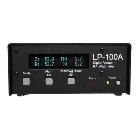
TelePost LP-100 User manual

1
LP-100
Digital Vector
HFWattmeter
Operating &
AssemblyManual
April 2007
TelePost Incorporated
Rev. C20

2
Compliance Statements…
FederalCommunicationsCommission
Statement(USA)
Thisdevice complieswithPart15 oftheFCC Rules. Operation issubjecttothefollowing two
conditions:(1)thisdevice maynotcauseharmfulinterference,and (2)thisdevice mustacceptany
interferencereceived, including interferencethatmaycauseundesiredoperation.
EuropeanUnionDeclaration ofConformity
TelePostInc. declaresthattheproduct:
ProductName:DigitalVectorRFWattmeter
ModelNumber:LP-100
Conformstothefollowing ProductSpecifications:
EN55022:1998Class B
following theprovisionsoftheElectromagneticCompatibilityDirective89/336/EEC,testedandverified
3-17-2006 atFCC accreditedlaboratory.
IndustryCanadaComplianceStatement
CanadaDigitalApparatusEMIStandard
ThisClass Bdigitalapparatusmeetsall therequirementsoftheCanadianInterference-Causing
EquipmentRegulations.
Cetappareil numeriquedelaclasseBrespectetouteslesexigencesdu Reglementsurlematerial
brouilleurdu Canada.
CopyrightandTrademarkDisclosures
LP-100 isatrademarkofTelePostInc. Windows®isaregistered trademarkof Microsoft Corporation.Teflon®isa
registered trademark of E.I. du Pontde Nemoursand Company.PICmicro®isaregistered trademarkof MicroChip
TechnologyInc.
Materialinthisdocument copyrighted ©2007 TelePost Inc. Allrightsreserved.Allfirmwareand softwareused inthe LP-
100, LP-100 VCPand LP-100 Plotprogramscopyrighted ©2004-2007 TelePostInc.Allrightsreserved. MicroCode
Loaderisacopyrighted programfromMecanique, http://www.mecanique.co.uk/.

3
TableofContents
Introduction............................................................................................................4
PartsList.................................................................................................................5
AssemblyInstructions............................................................................................8
InitialCheckout....................................................................................................16
Setup/Calibration..................................................................................................18
Operation..............................................................................................................22
CircuitDescription ...............................................................................................26
Schematic............................................................................................................28
Troubleshooting ...................................................................................................30
Software................................................................................................................32
SpecificationsandCALTable.............................................................................34
Warranty..............................................................................................................35
AppendixA..........................................................................................................36

4
Introduction
TheLP-100isdesignedasan accurateinstrumentformonitoringstationperformance. It providesanumberofuniquefeaturesnotseen
beforeinahamradiowattmeter.
Themost obviousof theseisthevectordisplay.Thisdisplayshowsthecompleximpedanceoftheloadintwoways. Thetoplineof the
displayshowsimpedanceinpolarform…i.e.,magnitudeandphaseoftheimpedance.Thebottomlineshowstherealandimaginary
componentsofimpedance…i.e., R+jX.Theparametersaredisplayedinarangeof0.1to999.9ohms.Phaseisdisplayedin0.1
degreeincrementsfrom0-180 degrees.
Featuresinclude…
•PLEDdisplaywithbargraphsforpowerandSWR, alongwithnumericalreadout forboth
•ProfessionaldBm/ ReturnLoss display
•50 mWto2500Wwithfourautorangingscales
•Powerdisplayresolution of0.01to1Wdependingon scale
•Frequencycoverageof 1.8-54MHz,withautomaticband-by-bandcompensation
•Z, R,|X|displayfrom0-999.9ohmseach
•Separatecouplerwith50ohmportsforuncluttereddesktop
•Peak-hold numerical powerreadoutwith"hang"characteristicforpowerandSWR
•SWRaccuracy<.15(5%)fromabout.1Wto2500W, .05 typical
•Poweraccuracyis5%typical atanyrated powerlevelorfrequencyfrom.5Wto2500Waftercalibration,usable to0.05W
•Canbeeasilymatched in thefield toexternal standardtowithin0.1%on eachband
•Powerdisplayisactual powerdeliveredtotheload(FwdminusRefpower).
•SWRAlarmsystemwithsetpointsforOff, 1.5,2.0.2.5and3.0.
•WindowsfreewareVirtual Control Panel forsoftware/ remotecontrol
•Supportwithin TRX-Managerfordirect remotemonitoring
•Advanced charting capabilityforSWR, RL, Z, R, Xandphaseanglevs.frequency
•Built-inbootloadertoallowforfirmwareupgradestobedownloadedand installed.
•Callsignscreen savertoextend lifeof display
•Directinput forbenchtesting &field strengthmeasurements, -15 to+33dBm.
•ConformstoFCCPart 15A&B, ICAS andCEradiated emission limits,tested andverified byaccredited lab
Thismanualwilladdress theassemblyof theLP-100,initialcheckout,calibrationandoperation.You maywishtoread throughthe
circuitdescriptionandstudytheschematicbeforebeginning assemblytofamiliarizeyourselfwiththeproject. It ishighlyrecommended
thatyouthoroughlyread throughthe Assembly section beforeevenunpacking theLP-100kit.
RoHSStatement
TheEUadoptedaset of standardsforthe“ReductionofHazardousSubstances”inJuly2006.Thereisconsiderableconfusionover
whichdevicesandcompaniesareaffectedbythenewrules.It isouropinion thathome-builtkitsareexemptfromthislegislation,and
theremaywellbeafurtherexemption undertheheading“Measurement Equipment”fortheLP-100.Also,sinceTelePostdoesnothave
apresenceinEurope,wedo notimporttoorexportfromamemberState, asstipulatedintherules.
Regardless oftheseexemptions,everyefforthasbeenmadetoprovide100%RoHScompliantparts,PCBsandSMTassembly
processesontheLP-100.Werecommend theuseof standardPb/SnalloysoldersforassemblyofLP-100kits,mainlyforperformance
reasons.Thisisperfectlyacceptableundertherulesfor“ownusebuiltequipment(hobbyist)”.Useoflead-free solderisalso
permissible,sincethePCBsarelead-free, butbeawarethat specialequipmentandtechniquesarerequiredtouselead-free solder,
and PCBreworkhasamuchhigherchanceofdamagingthePCB.
Inlayman’sterms,theLP-100isaslead-free aspossiblewithoutcompromisingperformanceorlong-termreliability,andbuildersin
memberStatesarefree toassembleanLP-100withwhateversoldertheywish.
HardwareUpgrades
Starting withserial#101, theLP-100usesan upgradedPICprocessor, withtwicethememoryofthepreviouschip.Thisallowsfor
yearsoffirmwaredevelopmentandaddedfeatures.AnyownerofanearlierLP-100isentitledtoafree upgradetothenewprocessor,
but willneedtodo anadditionalcalibrationtotakeadvantageofthenewcapabilities.AsaconveniencetoanyLP-100 owner,TelePost
will do thechipswapandafree recalibrationiftheownerreturnstheLP-100toTelePostathisshipping expense, and paysforreturn
shipping($12 forFedexGroundinsured).Alternatively,TelePostcanshipanewprocessortotheownerinexchangefortheoldone, or
forasmall chargeiftheownerwishestokeeptheoldprocessorasabackup.Inthiscase,itisuptotheownertorecalibratehismeter,
and tosaveandre-programhisCALtableintothenewchip. Fordetailsonchipswapping, send an emailto larry@telepostinc.com.

5
PartsList- Subject tochangewithout notice.
Pre-installedSMTparts
QTY PartNo. Description
4C9,10,12,13 0.01uF50V
2R4,18 Resistor26.71%.25W
2R5, 12 Resistor49.91%.5W
2R6,21 Resistor56.21%.25W
2R9, 27 Resistor56.21%.5W
2R10,20 Resistor4221%.25W
1R24 Resistor1741%.25W
1R30 Resistor1201%.25W
1R33 Resistor32.41%.25W
1R35 Resistor751%.25W
1D8 HSMS-2805 dualSchottky diode
1U1 AD8302
1U9 AD8367
1U10 Gali-74MMIC
1T1 ADP-2-1Transformer
Partstobeinstalled–mainchassis
QTY PartNo. Description
14 C1,2,5,6,7,11,14,20,22,32,33,40,42,43 0.1uF50Vmarked104
3C3,27,41 10uF50V
1C4 0.33uF50Vmarked334
8C8,21,28,29,30,34,38,39 0.01uF50Vmarked103
7C15,16,17,18,19,31,35 1uF50Vmarked105
2C23,24 0.001marked102
2C25,26 0.002marked202
1C36 330pF50Vmarked331
1D2 Rt.Ang. LEDRed
1D3 Rt.Ang. LEDGreen
1D4 1N4001
1D5 1N4148
1RC1 ribbon cableassembly
2J1,P1 16-pinDILheaderfordisplay
2J2,7 BNC jack,rt. angle
1J3 Powerjack2.5mm
1J4 DB9PCBmount
1J6 DualRCAPCBmount
2JP1,2 2-pinSILheader
2Shortingjumper
4L1,2,3,7 470 uH, 100 mAmoldedchoke(largebrown)(yel-viol-br-silver)
or1mH, 100mAmoldedchoke(largegreen)(br-blk-red-gold)
2 L4,6 470uH,30mAmoldedchoke(small greenorbrown)(yel-viol-br-gold)
1L5 1 mH,30 mAmoldedchoke(mediumgreen)(br-blk-red-silver)
or1mH, 100mAmoldedchoke(largegreen)(br-blk-red-gold)
1Q1 2N4401
1 LCD-1 PLEDdisplay20x2
2R1,13 1M1%1/8wbr-blk-blk-yel-br
3R2,41,42 10k5%1/8wbr-blk-or
3R3,16,17 1k5%1/4wbr-blk-red(maybe1/8wdepending onboardversion)
5R7,11,14,34,36 1k5%1/8Wbr-blk-red
1R8 20kpot
1R15 22k5%1/8Wred-red-or

6
QTY PartNo. Description
2R19,29 4.75%1/4Wyel-viol-gold
1R22 150k1%1/8Wbr-grn-blk-or-br
2R23,25 10k1%1/8wbr-blk-blk-red-br
1R26 6.34k1%1/8Wblu-or-yel-br-br
1R31 100 5%1/8Wbr-blk-br
1R32 174 1%1/8or1/4Wbr-viol-yel-blk-br
1R37 57.61%1/8or1/4Wgrn-viol-blu-gold-br(bluebody)
1R39 120 5%1Wbr-red-blk-blk-br(brownorrust coloredbody)
1RL1 OmronG5V-2-H1-DC5
1S1 CEM-1212CPiezotransducer
3SW1,2, 3 4mm tactileswitch,rt. Angle
3Switchkeycaps
1T2 ToroidcoreFT37-61
1U2 LM7805
1U3 18F2620
1U4 TLC-271ACP
1 U5 MAX6225BEPA
1U6 MAX232N
1U7 LM34DZ
1 U8 MCP3304
1Y1 Resonator10 MHz
1#28 wireforxfmr (2)6”(15.24cm)lengths–twocolors
1PwrCable2.5mm
1Enclosure MainEnclosure(top&bottom)
1PCB MainPCBw/pre-installedSMTparts
1Heatsink Heatsinkfor7805regulator
2ICSocket 8-pinsockets
2 ICSocket 16-pinsockets(Socket notusedfortherelay)
1ICSocket 28-pinsocket
4RubberFeet Square
Partstobeinstalled–coupler
QTY PartNo. Description
1Enclosure Coupler
1PCB Coupler
2T1,2 ToroidcoresFT140-61
2UHFConnector SO-239
2BNC Connector UG1094/U
2BNC cable 6'(1.83m)M/M–RG58U
4R3, 4,9,10 75 ohm1%1W(2512SMT)
8R1, 2,5-8,11,12 301 ohm1%1W(2512SMT)
2Nylonbushings Onewith3/16”(4.76mm)hole, onewith¼”(6.35mm)hole,3/16”(4.76mm)&1/8”
(3.18mm)onserial#safter200)
6AdhesiveTeflon®tape 2 long and 4shortpieces(2long&2short onserial#safter200)
1TerminalStrip 2lug terminalstrip
1#20 wireforxfmrs (2)45”(1.14m)lengths
1RG-142B/UTeflon®coax (1)2”(5.08cm)length
1RG-316UTeflon®coax (1)2”(5.08cm)length
4RubberFeet Round
1AdhesiveLabel CouplerTop Label

7
Hardware
QTY PartNo. Description
1 4-40x1.5”(3.81cm)threadedstandoff(.625”(1.59cm)onserial#safter200)
1 4-40x0.75”(1.91cm)machinescrew(serial#safter200)
14 #4 self-tappingscrews–1/4”(6.35mm)–plated(forcoupler)
14 #4 lockwashers(9forcoupler,3formainchassis)
(11 forcoupler,3formainchassisstarting about serial#350)
1#4 splitlockwasherforcouplerPCB
10 4-40x3/8”(9.53mm)machinescrews–plated(8forSO-239s,2forDB9)
(plus1forattaching voltagexfmrstandoffstarting about serial#350)
54-40x1/4”(6.35mm)machinescrews–plated(3forcoupler,1forheatsink)
(1fewerstartingaboutserial#350)
9 4-40nuts–large(forcoupler)
44-40nuts–small(1forcouplerPCB,3formainchassis)
16 4-40x3/16”(4.76mm)machinescrews–black(formainchassis)
84-40x¼”(6.35mm)threadedstandoffs(formainchassis)
6#4 x¼” (6.35mm)self-tapping screws–black(formainenclosure)
1#4 x3/8”(9.53mm)self-tappingscrew–black(forRCAconnector)
1#4 SolderLug(2onserial#safter200)
You shouldcheckall partsbeforestartingtoallowyou tostarttheprocess ofobtainingreplacement partsassoonaspossible.It isalso
agoodideatosort thepartsinadvance…egg cartonsarehandyforthis(passivepartsonly).Michael’scraftsstoresalsohavenice
plasticcaseswithdividersatlowprices. Note: partssubject tochangewithoutnotice.Forinstance,thereareacouplecaseswherea
resistoriscalledoutfor1/8Wwherethesuppliedonemightbe¼W,asinR33 &R37. Also,theoriginalpartforR39 wasacompact1W
resistorwherethecurrentpartislarger. Thisisduetosketchyavailabilityoftheearlierparts.ThePCBlayoutwillberevisedinthe
futureifitbecomesclearthattheoriginalpartswillnolongerbeavailable.Inthecaseofthelargerresistors,justformtheleadsunder
thepartasshownbelowif thishappens.Thiscan alsohappenwithlead spacingoncaps.

8
Assembly
Importantwarnings–readthisbeforestartingassembly
You shouldvisuallyinspectallthesolderpads/traceswithamagnifierforanyetchingproblems.Thisisdonebeforeshipping,butI
recommendthebuilderdoasecond inspectionaswell. Wealsonowdo 100%continuitychecks ofall padsbeforeshipment, and I
recommendthebuilderdothisaswell.Thisisaresultofacouplebadboardsfoundinproduction run#3. Thesetwostepswilltake
about15minutes,butcouldsavealotof work. Todothecontinuitycheck,turntheboardupsidedown,andconnectonelead ofyour
DMM tothegroundplane. Toucheachpadonthebottomthat isnotathermalgroundpad(onewitha“+”shapedconnectiontothe
groundplane).Noneof thenormalpadsshouldhavecontinuitytoground except fortwonearT1,theSMTxfmr,whichprovidesaDC
pathtogroundforthosepads. NOTE:thedozensoflittle“vias”tiethetoptothebottomgroundplanes,andthesedo notneedtobe
checkedastheyaresupposedtobegrounded.
AlloftheSMTcomponentsarepre-installedonthemainboardforyourconvenience. SMTpartsaresuppliedwherevernecessaryfor
performanceoravailabilityreasons. CAUTION: Beverycarefulhandlingthisboardtoavoiddamagetotheinstalledparts. Anti-static
measuresarehighlyrecommended,suchasuseof ananti-staticmat,groundedsolderingironandwrist band.
You maywishtoclean thefluxfromtheboardafterassembly,althoughitisnotnecessarywithmost modernsolders. Atoothbrushand
alcoholaregood forthis. Onlyuserosincoresolder.Useofacidcoresoldervoidsthewarranty.Lead-free solderisOK,andtheboards
areRoHScompliant, butitwillbemoredifficulttoremovepartswithout damagingtheboardshouldyouhaveto.
Overview
BelowisapartslayoutofthemainPCB.Thesemarkingsmatchthesilk-screening onthePCB, butarerepeatedhereforclarity. You
can alsocrossoutthepartsonthisgraphicastheyareinstalled. Note: DONOTusethismanualforassemblyofkitswithserial
numbersbefore#101.UseLP-100 ManualRev. BlistedontheLP-100webpageat www.telepostinc.com/lp100.html instead.Some
picturesinthismanualareof boardsorcomponentsfromearlierproduction runs.Thesemaybeslightlydifferentthanlaterversions.
Forinstance, L8, R28,C44, andC45weredeletedon laterversions,andC27andJ8werechanged.

9
Assemblycont’d
Irecommendapproachingassemblyinthefollowingorder…
Install all ICsockets
Install resistors
Install capacitors
Install connectorsandswitches
Install 7805regulator
Install chokesselectivelyasoutlinedintheinstructions
Thisallowstheboardtoremainflat duringmostoftheconstruction.Followingthisorderwill alsofacilitateinitialcheckout.Thechokes
will beselectivelyinstalledtoallowforcheckoutof varioussectionsofthecircuit.
Checkout will followthisorder…
Verifyproper+5vdcbeforepoweringanydevices
Install L2, PICandPLEDandcheckdisplayforproperPICoperation
Install L1, L3,U5,U7and U8andverifyproperoperationofADC
Install L5andU4andverifyproperpowerdetection
Install L7andverifyproperfrequency counteroperation
Install U6and verifyproperserialportoperation
Theabovechecks willrequireonlyaDVMand theSetupscreensexcept forthepowerdisplaycheck.Tocheck thepowerdisplay,you
will needatransmitterandcompletedcoupler.Iwill list expectedcurrentdraininredateachstepsothatyoucanverifythat nothingis
shortedineachsection.Acurrentlimitedorfusedpowersupplywith0.25ampmaximumfuseshouldbeusedduringcheckout.
TocalibratethepowerreadingsoftheLP-100willrequireaminimumofanaccurate50-ohmdummyload and ameanstomeasurerf
power. Youwillneedadiodepeakdetectororacalibratedoscilloscopetomeasurerfvoltageacross theload. Analternativewouldbe
an accuratereferencewattmeter.
Tocalibratetheimpedancegainandphasedetectorsyouwillalsoneeda25ohmdummyload.Thiscanbeeasilymadeupout of
inexpensive3W,5%metaloxideresistors, suchasusedinmyLP-200ortheElecraftDL-1.Alternatively,youcanuseapairof50ohm
dummyloadswithcoaxadapterstoallowthemtobeparalleledtoprovide25 ohms.Thiscalibrationcanbedonewithaslittleas5Wof
power. Thisadjustment isnot imperative, asthedefaultvalueisquiteacceptable.
SWRcalibrationrequiressettingoffset andslopeadjustmentsfortheAD8302gaindetector.Calibration oftheAD8302 phasedetector
requiresadelaylineofknownelectricallength. Youcangetprettyclosebyusing ahighqualitypieceof polydielectricRG-58,and
calculatetheelectricallengthindegreesusingthefollowingformula…
Phase=(360*L*F)/(984*VF)
WhereDelayisindegrees, Lisinfeet and FinMHz. VFwouldbe0.66forpolydielectric.Aconvenientlengthisabout6’(1.83m),
whichwouldprovideadelayof~45degrees(thecenteroftherange)at14MHz. Youwillfindmoreaboutcalibrationinthe Calibration
section.I amcontemplatinganinexpensivecalibration kitinthe$25 range,whichwouldincludeaswitchabledummyload PCBand
pre-cutdelayline.IwillalsocalibrateanyassembledLP-100kitfree ofchargeif you payforreturnshipping.
You willneedthefollowingtoolstocompleteassembly…
Adjustablesolderingiron–800degreesmaximum
60/40alloysolder….020”(0.51mm)diameterrecommendedforthermalpads
Needle-nosepliers
Wirecutters
SmallPhilipshead screwdriver
Razorknife
DigitalMultimeter
NOTE:TheLP-100iswhatIwouldcall anintermediatelevelkit. Ifcareistaken,you shouldhavenodifficultybuildingit. Iwouldpegthe
assemblytimeat about8hourstotal,plussomereadingthrough themanualinadvance,and sometimeforcalibration. Takeyourtime,
and double-checkyourwork. Achangewasmadeafterserial#100tomakethethermalpadstoground easiertosolder. Theboardis
nowalsoRoHScompliant.Thisshouldnot poseanyproblem.Infact,I findthenewerboardseasiertosolder.

10
Assemblycont’d
Step-by-step assemblyinstructionsformainboard.
Belowisapictureof theassembledPCB.TheSMTpartscomepre-installed.
Itisrecommendedthat you print thismanualtoallowforeasy referencewhilebuilding,andtoallowyou tocheck offthestepsasyou
completethem. Therewillalsobeatableofcalibrationvaluesyou canenterasyoudothecalibration. Thiswill enableyoutoreturnto
theoriginalsettingsshouldyouneedtointhefuture.
Makesureyourworkareaisstatic-free toavoiddamagetothepre-installedSMTparts.Itisalsoadvisabletowearananti-staticwrist
band.Refertothepartsplacement graphiconpage6ortheabovepictureforquestionsregardingpartsplacement. Youcan zoominto
thepdfversionof thisdocumentforeasierpartsidentificationifneeded.
qInstall all ICsockets,keeping theboardflatasyougotoavoidgaps.
qInstall resistors. Toavoidmessiness whentrimmingleads,Iwoulddo about 6at atime.Ifyouareunsureofthecolorsusedby
someofthemanufacturersforthecolorcode,measurethevaluewithaDMM.
qInstall all .01uFcaps(marked103),ingroupsof about6.
qInstall all .1uFcaps(marked104).Thisshouldbedoneinat leasttwobatches.Onsomeruns,thesepartshaveformedleads.You
can straightentheleadsarejust snap thepartinasdesigned.
qInstall remainingcaps,leaving the10uFcapsforlast. Observepolarityonelectrolytics. Referringtothecomponentplacement
guideandpicturemayhelpwithpartsplacement,forinstanceforC27whichwaschangedtoanelectrolytic.
qInstall greenand redLEDs. NOTE: Donotinstallthesetightagainsttheboard.Becauseof manufacturingtolerancesonthese
parts,theymaynotlineupwiththefrontpanelholeswheninstalledtight againsttheboard.Itisdesirabletoleaveabout 1/16”of
spacing belowtheLEDs,sothat theycanbebentforwardtolineup ifnecessary.

11
Assemblycont’d
qInstall miscellaneouspartssuchasresonator,Piezotransducer,transistor,diodes, etc. NOTE:Removetheprotectivecoveringon
thetransducerbeforeusing.Also, the“+”lead goestothesidewiththejumper,pertheplacement guide.Theoutsideleadsofthe
resonatorareinterchangeable. Donot install chokesyet.
qInstall connectorsandswitches, except forJ4,theDB9connector. Youwill probablyhavetopropsectionsof theboardupto
ensurethat thepartsareflushwiththeboard.Install theheaderonthePLEDPCB.Theheaderisinstalledon thebacksideofthe
PLEDPCBwiththelongpinspointing awayfromtheboard.
qInstall 7805regulator.Attachheatsinktotheregulatorbeforeinstallingon PCB,using 4-40x¼” (6.35mm)”machinescrewand
smallhexnut.Itdoesn’t matterwhichsidethenutison.
qInstall T2nearC43. Thisxfmrismadeupof 10bifilarturnsof#28 enameledwirewoundonaFT37-61core.Wireissuppliedin
redand greentomakewiringasnap.Bifilarmeansthatthetwowiresarewoundasapair. See diagramaboveforwiring.It does
notmatterifthewiresareparallelortwisted. Aturnisdefinedasapassthroughthecenterofthecore. Youwillwindupwiththree
leads,whichwillbeinsertedintothethree holesindicatedonthesilk-screen. Thelead withtwowiresgoestothecenterholeinthe
PCB. Makesurethattheenamelisremovedfromtheleadsbeforesolderingtoensuregoodcontact.
qInstall L4andL6.Theremainingchokeswillbeinstalledaspartoftheinitialcheckoutoftheboard,inordertoenablepoweringup
ofcircuitsindividually.Thesemaybebrownorgreen, butaresmallerthantheotherchokes. NOTE:Ifyoucheckthechokeswitha
meterliketheAADE,thereadingsmaybelow. Thisisbecausethechokesuseferritecores,andtheLvarieswithfrequency. The
littlemeterstendtotestatverylowfrequencies.
qThejumpersforthePTT connectorcan bewirednow.Thenormalwiringisshownonthecomponent placementdiagramatthe
beginningofthischapter,andbelow.Thisprovidesforanormallyclosedconnection betweenthecenterconductorsofthetwo
RCAconnectors. Thiswillworkformost rig/ampcombinations.FormoreoptionsforPTTwiring,check out theSteppIRTuning
Relaysectionof mywebpage.
qAttachJ4,theDB-9connectortothePCBusing4-40x3/8”(9.53mm)screws,lockwashersandsmallhexnuts.Thelockwashers
and nutsgoon thebottomoftheboard.Solderthepinsaftertighteningthescrewstoavoidstressingthepinsaftersoldering.
qYou caninstall RL1atthistime.Thecorrectpositioningiswiththetwoseparatedpinstowardthebackoftheboard,next tothe
snubberdiode,D5.Thenotchinthetopisalsopositionednext tothediode.See thecomponent placementillustration.I usedto
supplyasocketforthis,but havedecidedthatthere’sreallynoneedforit, andthere’sariskoftherelayworkinglooseduring
shipment.

12
Assemblycont’d
Initialcheckoutofmainboard.
qStep1.Makesurethatyourbenchisclean andthePCBisnotsitting on anycutoffcomponentleads.Connectsuppliedpower
cabletoasupplyof12-15VDC. Thedashedwhitelead on thesuppliedpowercableisthe+lead (centerpin). Makesureyouhave
ajumperinstalledatJP2.Using yourDMM,check for5.0VDC at pin3ofU2.Thevoltageshouldbewithin0.25Vof 5.0VDC. ~7
mA.
qRemovepowerand installL2,U7,Y1andthePIC.TemporarilyconnectthePLEDdisplay. Becarefultomakesurethereisnothing
on yourbenchwhichcouldshortout anythingonthePLEDPCB. Theribboncableshouldbeorientedasshownintheinterior
photobelow.Makesurethattheribbon connectorsarecenteredon theheadersat bothends.
qStep2.Powertheboardupagain,andverifythatyouareseeing the“splash”screenwithversionandcopyright information,
followedbythemainLP-100 screen. Themainscreenshouldlooklikethescreenon thephotoatthetop ofthe“Operation”section
ofthismanual.Ifyoudon’tsee thedisplay,adjustthesettingof R8.Thepropersettingisjustat thepointwherethedisplay
reachesmaximumbrightness.Thiswill ensurethatthebrightnessdropstotheproperlevelwhenthefirststepofthescreensaver
timerisreached. Afineradjustmentcanbemadeafterthescreen-saverstarts.ThecorrectvoltageforthePLEDat thejunctionof
R8andR15 is3.0Vatfullbrightness whiledisplayingthemainscreen.It willdrop to2.4–2.5Vinthescreensavermode. ~35
mA
qStep3.InstallL1,L3, U5,andU8. ~82mA.TemporarilyentertheSetupmodebybrieflypressingtheMode(SW1)and Alarm
(SW2)buttonsalmost simultaneously. TheModebutton shouldbepressedslightlyahead oftheAlarmbutton. NOTE: Startingwith
firmwareversion1.1.44, entering(orexiting)SetupisaccomplishedbyholdingtheModebuttonforabout aseconduntil thescreen
changes. You shouldnowsee thefirstCalibratescreen, shownbelowforfirmwarepriorto1.1.47.Thesecond screenisfor
firmware1.1.47andafter. ThisscreenshowsthereferencevoltagegeneratedbyU1(thegain/phasedetector),theReceived
SignalStrengthIndicatorvoltagefromU9(theAGCchip)and temperatureindegreesFand C(fromthetempsensor, U7). Note:
theRSSIreadingshowninthisphotoiswithRFpowerapplied. Theresting voltagewithnoRFisgenerallybetween.150and.250.
NewerfirmwaredisplaysTempindegreesCorFdepending ontheselection.
qStep4.InstallL5,L7, U4andU6andcheck thecurrent. ~160 mA. Ifalliswell, settheboardasideuntil thecouplerassemblyis
completedtoallowcheckoutofthepowerdetectorcircuitand frequency counter.

13
Assemblycont’d
Step-by-step assemblyinstructionsforthecoupler.
Refertothedrawingandpicturesduringassemblyofthecoupler.Thetop pictureiscourtesyofDario,N5QVF,andthelowerrightone
iscourtesy ofStan, W5EWA. Thesequenceof picturesbelowisfromJackK8ZOA.Jackdevelopedacleverwaytoensureproper
winding ofthecores,bothforspacing andcoverageofthewindings.Detailsof Jack’swindingmethodologyisfoundbelow.

14
Assemblycont’d
Constructionofthecouplerconsistsofonlyafewsteps. Themaincomponentsarethetransmissionline,toroidaltransformersand the
attenuatorPCB.Themost criticalstepisthewindingofthetransformers. Theyarewoundwith26turnseachof#20 enameledwire.
Thecoresarewound inoppositedirections,i.e. theyshouldbemirrorimagesof eachother. Thewindingsshouldbeevenlyspaced
over~60%ofthecore, asshownlater.ThecoresaresupportedbynylonbushingswithTeflon tapeoverthem,whichareinsertedinto
thecorecentersafterwinding.If thewiresarewoundtightly,thecoresshouldfit snugly,butshouldnothavetobeforced.Thecores
shouldbewoundbyhand,don’t useanytoolsonthecoresorwiresastheymaybreak.
HerearesomedetailsofthewindingaidthatJack,K8ZOAdeveloped. He
createdtheruleusingExcel,using thefollowingmethod.
Start withafreshExcelworkbook.Clickontheupperleftcell,andselect
underline. Rightclickandselectcopy,thenhighlightcells2thru25inrow1,
rightclickand select paste. You shouldnowhaveastackof25 linesinrow1.
Adjustrowheight for0.10" (2.54mm)betweenlines, whichcorrespondstoa
rowheightof7.2.Dothisbyhighlightingthe25rows,selectFormat>Row>
Heightinthetoolbar,andsetrowheightto7.2. Thisgives60%coverage
whichmatchesthesmallTeflontapesizegap.Copythecellsandpasteextra
copiessothat you willhaveatleasttwotouseafterprinting.
Thereducedsizescreencapturetotherightshowswhatthescreenshould
looklikebeforeprinting.Print thescreen, cuttotherulesout and tapetothe
cores. Useawhitelaundrymarkerorgreasepenciltomarkthelinesonthe
toroids.Jackrecommendstheuseofatightfitting corktoholdthewindings
inplaceasyou proceed, and tohelpflattenthewireagainstthecoreonthe
inside.
ThebushingwiththelargerholeismountedbetweentheSO-239
connectors,andsupportedbytheRG-142 Teflon®coax. Thispieceof coax
formstheprimarywinding ofthecurrent samplingtransformer.Theother
transformerissupportedbya0.625”(1.59cm)standoffand1.0”(2.54cm)
screwwhichformstheprimaryofthevoltagesampling transformer. Oneend
ofthisstandoffisgrounded,andtheotherconnectstotheattenuatorPCB.
Thetransformersecondariesarewiredasshowninthedrawing.Itis
importantthatthecoresbepositionedasshown,andthewiresberoutedas
shown.Improperrouting orcoreorientationwillaffectperformance,
especiallyabove25 MHz.
qInstall thetwoSO-239UHFconnectorsusing 4-40x3/8”(9.53mm)machinescrews, #4lockwashersand large#4hexnutsfor7of
themountingholes. Theremaining hole,uses4-40 x3/8”(9.53mm)hardwareandasolderlug asshown. Thesoldercupsonthe
SO-239sshouldbefacingupward.
qSoldertwoshortpigtailsabout 1.5”(3.81cm)longintothecenterpinofthetwoBNCs. You can usecut endsfromotherpartsfor
this.InstallthetwoBNCconnectorsusingthesuppliedspecialhardware,including solderlugs, asshown.

15
Assemblycont’d
qPreparethetwopiecesofcoaxasshowninthediagram.Makesurethattheshieldwiresdon’tshortouttothecenterconductoron
eitherend. RG-142isdoublesilvershielded.Leavealittleshieldshowing on oneend asshowninthepics above,and thenwrap a
short pigtailof wirearoundit.It issafetoapplyareasonableamountof heattotheTefloncoaxwithoutworryabout melting the
insulation.
qWind26turnsof#20enameledwireon eachoftheFT140-61 cores.. Thecoreswillbewoundinoppositedirections,sothatthe
finishedtoroidswillbemirrorimagesofeachother.Awinding isdefinedasthewirepassing throughthecenterofthecore. If you
countwindingson theoutsideedgeofthecore,yourcount will beoneshortoftheactualnumberof turns.Mis-countingbyoneturn
will giveyou apowerreadingerrorof8%,andcauseotherproblemsaswell.Thecurrentsamplingxfmrisinstalledbetweenthe
SO-239 connectors, andwill besupportedbytheshortpieceof Teflon®coax. Thevoltagesamplingxfmrissupportedbythelong
standoff.Leave1”(2.54cm)longpigtailsonthexfmrsexcept forthelead that exitsfromthebackofthevoltagexfmr (lowerright
lead inthelowerright picturebelow),whichshouldbe3”(7.62cm)long (shownexitingtheframeinthepicture). Scrapetheenamel
offtheendsof theshortleads. Arazorknifeorsandpaperisgoodforthis. Note:It isbesttoscrapetheenameloff, asthesupplied
wiremayormaynotbeheatstrippable.Wind thewiretightly.Useyourfingerstokeepthewindingsformed closetothecoreson
theinside.
qBeforeslippingthenylonbushingsintothewoundcores,takethetwolongpiecesof Teflon®tape, peelthepaperoffofthe
adhesiveside, andwrapeachofthenylonbushingswiththeTeflon®tape. Thentaketheshortpieces,removethepaper,andstick
theminthecoresbetweenthewindings.Thiswillmakeforatight fitinsidethetoroidcores,andwillalsoservetokeepthe
windingsproperlypositionedaround thecores. Beforeslidingthecoresinplace,makesurethattheinsideofthewindingsisflat
againstthecores.BecarefulwhenpushingthecoresinplacenottodislodgetheTeflon®tape. See thepicturebelow.Note: The
pictureshowsthevoltagexfmr withtheolderbushingwith¼”(6.35mm)hole. Thelatest versionis1/8”(3.18mm).Theoldpicture
alsoshowsaslightlydifferentmixofTeflon®tape.

16
Assemblycont’d
qSolderthe12SMTresistorsontotheattenuatorboardasshown. Don’t beafraidoftheseparts.TheseareVERYbigpartsasSMT
goes. Theresistorvaluesareprintedontheresistors.Useafinetiponthesoldering iron,andtinONEofthePCBpadsforeach
resistorwithasmallamountof solderbeforeattempting tosoldertheresistors. Holdtheresistorsinplacewithatweezers, and
applyalittleheattotheedgebetweeneachpad and theboarduntilthesolderflowsbetweentheresistorand pad.It ishelpfulto
slidetheresistoroverthepadasit meltsontothesolderdrop,sothattheotherend exposesalittleofthepadontheotherside.
Soldertheothersideinplacebyapplyingheatand soldertotheedgewheretheresistorsitsonthepad.Thengobacktothe
tackedpadandtouchupifnecessary.Applyingalittlefluxtotheboardahead oftimewillhelptoholdthepartsinplaceand aidin
solderflow.Toverifytheproperinstallationoftheresistors, useanohmmetertocheck theresistanceof eachbarestripline
connectiontoground.Themounting holeisgrounded, aswellasthelong stripalongthetopedge. Eachpointshouldbeabout83
to84ohms.Ifnot,check yoursoldering.
qInstall thePCBontothesideofthecouplerabovetheBNCsas
shown.Theboardmountswiththeholenearthebottomedge.
Bend and solderthepigtailsfromtheBNCstothetwostriplines
nearthemounting hole.Use4-40x¼”(6.35mm)machinescrew,
thesmall splitlockwasherandsmall hexnuttomounttheboard.
qSolderonetheshortpieceof RG-316Upreparedearliertothe
solderterminalonthebottomofthecoupler,withthecoaxshield
connectingtothegroundedlug, and thecentertothelug that
connectstothecurrent samplingxfmr.
qSolderthecenterconductorfromtheotherend ofthecoaxtotheremainingPCBstriplinepad,andtheshieldtotheground lugon
thecenter-most BNC.
qSlidethecurrentsamplingtransformerovertheshort pieceofRG-142asshowninthediagrams,beingcarefultoposition the
windingsandthecoaxshieldasshown.Thisisatightfit, butifyoutakeyourtimeandrotatethecoaxasyoupress itintoplace,
you shouldn’thaveanytrouble.Thereseemstobealittlevariationinthediameterof theRG-142,soyou mayfind thatyou needto
filetheinsideof thebushingalittletoallowagoodfit.Thiscanbedonewithasmallrattailfile, arolledpieceof sandpaperora
reamer. Analternative,suggestedbyK8SIXistousea#10drillbit todrill theholeout alittle.
qThexfmrshouldbeorientedlevel,withthewindingsfacing up beforesoldering.Solderthecoaxon theshieldend intotheSO-239
connector,andtheshieldwiretothesolderlug ontheXMTRconnector. Cutthewirefromtheoutsideleft ofthetransformer
secondarytolengthand solderittothelugontheXMTRconnector. Theotherend ofthecoaxwillbesolderedalong withthelong
wirefromthevoltagexfmr inanupcomingstep.
qInstall the2-lug terminalstrip,thencutandsolderthewirecomingfromtheinsiderightsideof thexfmr totheinsulatedlugonthe
terminalstrip.
qPreparethevoltagexfmrasshowninthephotosonthebottomofpage13, using the0.625”(1.59cm)standoff,4-40x0.75”
(1.91cm)screw,lockwasherandsolderlug.Thelong lead shouldexitthecoreon thesidewiththestandoffasshowninthe
overhead pictureofthecoupler. Afterapprox. serial#350,alockwasherwasaddedbetweenthestandoffand nylon bushing.
qBend thesolderlug outatclosetoa90 degree angle,andsolderasmalllengthofdiscardedcomponentlead toit.
qAttachtheassemblytothesideofthecouplerusing4-40 x3/8”(9.53mm)hardware. Thesolderlug and pigtailshouldbefacing the
PCB.Itisimportantthatthisassemblybeattachedfirmlyoryouwill see erraticoperation.Alockwashershouldbeplacedbetween
thecouplerwallandstandoff,andonebetweenthescrewhead andoutsideof thecoupler.
qPrepareand soldertheshort end ofthetoroidwinding sothatitconnectstothesolderlugon theright-mostBNC.If thecoreis
mountedcorrectly,thiswireshouldcomeofftheright sideofthecorefromtheinside.Solderthepigtailfromthestandofftothe
striplinepad on theend ofthePCB.Leaveasmallbend inthislead toallowforflexing whenthetopisattachedtothecouplerand
thewallsarepulledapart.
qThelongwirecomingofftheoutsideleftsideof thecoregoestotheoutput SO-239as
shown.Theend ofthewireshouldbeplacedinsidetheSO-239centerconnector
alongsidetheRG-142centerconductor,orloopedaroundtheSO-239center
conductorasshowninthephotos.Besuretoscrapetheend toallowgood solderingin
eithercase.Beforesoldering thesewirestotheSO-239, thewallsof thecouplerneed
tobepre-tensionedsothattherewon’tbeanystress ontheRG-142whenthetopis
attachedtothecoupler.Todo this,Iusea2”(5.08cm)longstandoffplacedbetween
thewallsabovethexfmr toseparatethewallsslightly.Asuitablesubstitutewouldbea
2”(5.08cm)longpieceofwooddowel.Thewireshouldberoutedabout1/8”(3.18mm)
fromthecurrentxfmrasshown.Forbestphaseaccuracy at50MHz, alittlecoupling to
thecurrent xfmrsecondaryisdesirable. Removethespacer.

17
Assemblycont’d
qMakesurethatall connectionsaresolderedwell,andthat thecoresarelevel.Slipthetoponandattachwith(14)4-40 x¼”
(6.35mm)sheetmetalscrews. Applypressuretheendsof thecovertoprevent gapsfromformingasthescrewsaretightened.
qClean andwipethetopofthecoupler.Carefullylineupthetoplabelandapplystartingatoneend andsmoothingasyougoto
prevent theformation ofbubbles.
Final Checkoutand Assembly
Beforegoingthrough theSetup screens,itisnecessarytoverifythattheremainingbasiccircuitsareworking. PoweruptheLP-100,
and verifythat thecurrentdrawiscorrect.(160 mA ). ConnecttheCurrent and Voltageportsofthecontrollerandcouplertogether
usingthesupplied6’(1.83m)coaxcables. Youmaywanttobundlethecablesusingelectricaltapetomakeforaneaterinstallation.
Onecableshouldbemarkedwithcoloredtapeatbothendssothatthecablesarealwaysconnectedconsistentlyinthefuture.I also
marktheCurrentjacks on bothendssothatthecoloredcablealwaysconnectstoCurrent. Thispreventscrossingof thecables, and
alsoeliminateserrorsduetocablevariations.
Connect a50ohmdummyloadtotheLOADport. SelecttheFast modeforthedisplay(press Fast/Slowbuttonuntilyou see alower
case“w”afterthepowervalue),and applyasmallamountofpower. ThePowerand SWRbargraphsshoulddeflectupward,andthe
numericalreadoutsshoulddisplayanumberveryclosetotheexpectedvalue. Switchtothevectordisplay(press Modebuttononce),
and youshouldsee valuescloseto50ohmsforZand R, and closetozeroforphase.
Next, enterSetupmodeasdescribedinInitialSetup, and scrolltotheGain/PhaseZeroscreen. AdvancetotheGain/PhaseZero
screenbypressingModetwice. You shouldsee theband indicatedinthelowerleftcornerduringtransmission.Thisshouldmatchthe
band you aretransmitting on.TheBandindicatorshouldremainonthelastusedbandaftertransmission.
UsingtheAlarmSet button, settheAlarmfor“1.5”.Removethedummyload andtransmitintothecoupleratlowpower.TheRedAlarm
LEDshouldlighton thefrontpanel,andtherelayshouldclick. IfyouhaveJP1inplace,thePiezotransducershouldalsosound.Note:
thetransducerwillsoundprettyloud sinceit’snotinsideacaseatthispoint.Reconnectingthedummyloadwillcancelthealarmaftera
second orso. You can double-check thePTT connectionswithanohmmeteratthistime. Thecenterconductorsof theRCAconnectors
wouldbenormallyshortedtogether,andopenwhenthealarm sounds.
You arenowreadytoinstallthecontrollerboardinthecase. First, looselyinstallthe4-40x¼” (6.35mm)threadedstandoffsonthe
bottomofthecaseusing4-40x¼”(6.35mm)black machinescrews.Next, slidetheboardintotherearholesasyoudropthefront
downtowardthebottom.Becarefulnottoscrapethebottomoftheboardon thefrontpanelasyou slideit.
Oncetheboardisinplace,alignthefrontholeswiththeswitchesandLEDs,andscrewtheboarddownwithfourmore4-40 x¼”
(6.35mm)blackscrews.Tightenthebottomscrews. Theswitchcapswillbeinstalledaftercalibration,incaseaproblemshowsupthat
requiresremovaloftheboardfromthecase. Thecapscan bescratchedduringremovaliftheyareinstalled.
Install thefourremaining4-40x¼”(6.35mm)
standoffson thefront ofthePLEDPCB,using
four4-40x¼”(6.35mm)black machinescrews,
and tighten.Mount thePLEDPCBtothefront
usingtheremaining black machinescrews,and
install theribboncablebetweenthetwoPCBsas
showninthepicture. Don’tforgettoremovethe
protectivefilmfromthePLEDdisplaysurface
beforemounting. Again,makesurethat the
ribbon jacklinesupproperlywiththeheaderpins.
Thetop coverwillbeinstalledaftercalibration.
Connections…
Power: 11-15VDC,centerpin+,2.5mm.Thelead withthewhitestripeon thesuppliedcableis+
PTT: LoopthePTTbetweenyouramplifierandrigthrough theLP-100usingRCAconnectors
RS-232:Connectstocomputer…standardM-FstraightthroughDB9serialcable.
Current/Voltage:ConnecttocorrespondingjacksonthecouplerusingsuppliedRG-58Ucables.

18
Setup/Calibration
Note: Thissectionassumesyouareusingfirmwareversion1.1.1orlater,andof coursetheupgradePICprocessor.Ifyouownakit
fromthefirst productionrun(serial#100 orolder), thenitishighlyrecommendedthatyouupgradetothenewprocessorbefore
calibrationtoavoidhavingtocalibratetwice. Thisisanochargeupgrade(except forshippingcost).
EntertheSetup modeagainasdescribedinInitialCheckout.Belowyou willsee apictureof eachSetupscreenalongwithabrief
synopsisofwhatit doesandwhat thecontrolsadjust.Remember,forfirmware1.1.45orlater, it isasingle,long,Modebuttonpress.
Referencescreen.Displaysthereferencevoltagefromthegain/phasedetector,aswellastheRSSI
voltage(ReceivedSignal StrengthIndicator) fromtheAGCchipused in thefrequencycounterpreamp.
Thisvoltageisproportionaltothelog oftheRFinput powertotheLP-100. Thescreen alsoshows
temperatureinDegF &C. Therearenoadjustmentsforthisscreen.
Thisscreenallowsyou toentertheactual impedanceof yourdummyload. Thiswillresultinamore
accuratecalibration if yourdummyloadisotherthanexactly50.0ohms.
Thisadjustmentisused tocalibratethezeropoint (oroffset)ofthemagnitudeandphasedetectors. The
adjustmentissemi-automaticinthatyoudon’thavetomakeanyadjustments. Theprocess requiresyouto
brieflytransmit intoan accurate50ohmdummyloadon eachbandinsequence,andtopress theAlarm/Dn
button tosavethecorrectionforeachband.
Thisadjustmentisused tocalibratetheslopeofthephasedetector. Itissimplydonebyinsertingalinewith
knowndelayintotheCurrentinputoftheLP-100, andtransmittingintoahighquality50ohmdummyload.
The controlsarethen adjusted sothat thedisplaycorrectlyshowsthelinedelay. IfcoaxofknownVelocity
Factorisused, thelinelengthindegreescanbesimplycalculated.
Thisadjustmentisused tocalibratetheslopeofthegaindetector. It isaccomplished bytransmittingintoa
25 ohmloadandsettingtheTrimforareadingof25.0(orwhatevertheactual loadresistanceisifit’snot
exactly25.0).
Allowsadjustmentoftheaccuracyoftheop-ampdetectorandADC toprovidecorrect conversion valuesat
lowpowerlevels. Thescreen showstheoutputvoltageofthedetector, and theTrimlevelissetby
adjustingforzerovoltagewithnoRFpowerapplied.
AdjustsoverallpoweraccuracyoftheLP-100. Thisadjustmentaffectsallfrequenciesequally, and ismade
bycomparing theLP-100powerreadingwithan accuratereference. Acceptablereferencemeasurement
devicescan beinexpensivelymade,andwill bedescribed later.
Sameasabove,but adjuststhedisplayedpowerreadingon aband-by-band basis. Thebuilt-infrequency
counterdetectsthebandyou’reon, andstorestheCALconstantforeachbandautomaticallyfor12bands
from160mthrough4m.Thecounterworksfrom50 mWto2500W.
Thisscreenisused tomatchthereadingsofthelowpowerandhighpowerADC inputs.It isdoneata
powerlevelbelow320W, whichisthepoint at whichthelowpowerinputreachesmaximum.Itspurposeis
toallowcompensatingforanyerrorinthe1%precisiondividerpartsused inthehighpowerinput. NOTE:
MovedupbetweenOffsetandMasteron ver.1.1.47candlater.
ThisscreenallowssettingtheSWRAlarmpowerthresholdandPowerdisplaytype. Thealarmthresholdis
usedmainlyin contesting stationswithmultipletransmitterstoprevent falsealarmswhen energyfrom
anothertransmitterispicked upbyan antenna. Thechoicesare0,0.1,1.0, 10.0and100.0W. Thepower
Thisscreenallowsselection ofthecorrect cablecompensatingtabletomatchtheconnecting cablesyou
areusing.EarlyLP-100susedRG-174U,but achangewasmadetoRG-58Ustartingwit serial #101.
Startingwithserial#400, thismenuwaschangedtoaserial numberselection, andcoversanyhardware
changebetweenversionsinsteadofjust cables. Inthecaseof the5th run, itcoversthechangeinresponse
of aslightlydifferentmodelpowercombiner.

19
Setup/Calibration Cont’d
AllowseditingoftheGain/PhaseZeroCALvalues,whicharenormallygatheredautomatically. Thisis
useful forrestoringaccidentallychangedvalues.TheDnbutton adjustsgaintrim,andtheUpbuttonadjusts
phasetrim.
Allowssettingof maximumbargraph scalevaluesforallthree autoranging scales. TheDnbutton selects
Low,MidorHigh range,andtheUpbutton allowsscrollingthroughthe variousmaxpoweroptions.The
displayedrangeincludes0.4dBovershoot (~10%)abovetheindicatedvalue. Note: Theserangesdonot
affect thenumerical readout, whichhasnolimits. Defaultsare15W, 100W, and 1500W.
Thisscreenisused toset thewidthofthebargraphin theFastmode. Itisuseful foroptimizingthe
bargraphresolution foramplifiertuning, forinstance. Thedisplayedrangegoesfromthemaximumsetin
thepreviousscreen,toaminimumwhichistheselected numberofdBbelowthatmaximum. Default is6dB.
The nameof thisscreenwaschanged toFastBargraphRange.
Thisscreenallowssettingofthenumberofsamplesusedtoaveragethenumerical readout inFastmode.
The rangeis2to32samples. Thedefaultis8samples.
ThisscreenallowssettingthepeakholdtimeintheSlow(peak)mode.Therangeis0.25to5seconds.The
defaultof 3secondsisgood fornormalSSBorCWoperation.Thefastest settingcan beusefulforamplifier
tuning,especiallywhen a“pulser” isused.
Thisscreenisused toset the“User”SWRAlarmsetpoint. It can besetbetween1.0and5.0in stepsof 0.1.
Impedance Calibration
Calibration isdoneinacoupleofsteps. Firsttheimpedancemeasurementsystemiscalibrated,andthenpowerleveliscalibrated. The
requiredtoolsforthiscalibrationareahighquality50ohmdummyload,ahighqualitypowermeterorothermethod ofdetermining
powerasdescribedinthetext and ashortcoaxiallineofknownelectricallength.Asecond dummyload isalsodesirableforcalibrating
theslopeofthegaindetectorforimpedance,butnotabsolutelynecessaryasthisadjustmentseemstovaryonlyslightlyfrommeterto
meter.Inormallydo calibrationat 100W, butveryclosetofullaccuracycan behad withpoweraslowas5W,andsomewhatreduced
accuracyisattainabledownto<1W.
I amworkingona“calibrator”designwhichwoulduseinexpensive1%thickfilmresistorsor5%metaloxideresistorstoprovide
switchable50/25 ohmimpedancewitha10Wrating.It wouldincludeadiodepeakdetectorformeasuringpowerwithacalibratedtable
ofvoltagevs.power.Iamalsotesting amethodofusinga6’longlengthof RG-59Uwhich,whenterminatedwitha50ohmdummy
load, producesaknowncompleximpedance. ThisprovidesamoreaccuratewayofsettingtheGainandPhaseslopeadjustments,and
takesintoaccountcouplervariationsasopposedtothedelaylinemethod.Ihavecharacterizedreadilyavailableandinexpensive
cablesavailablefromJameco, RadioShackand Mouser,and willprovidepartnumbers.ThecablesareBNC-to-BNC,andmayrequire
UHFadaptersifyoudon’talreadyhavethem. Thesearealsoavailablefromtheabovesuppliers.
Thefirst calibrationscreenisthe“DummyLoadZ”screen, whichallowsfortheentryofyourdummyload’sactualimpedance. This
makescalibrationmoreaccuratewhenyourloadisnotexactly50ohms. UsetheDn/Upbuttonstosetthedisplaytomatchyourload’s
actualimpedance.Ifyoudon’thaveagoodwaytomeasureyourdummyload, you can measuretheresistanceatDC using aDMM.If
you knowtheload tobelow-inductancethrough 6m,thiswillgiveareasonableapproximation.Ifyou arelookingforahighquality
dummyload,checkoutwww.ridgeequipment.com. Theyhavesomeexcellent surplusloadsforaslittleas$10.
Thenext screenistheGain/PhaseZeroscreen. Thisallowsforband-by-bandbalancingof thegainandphasedetectors.Todo this,
connectyourdummyload totheANTconnectoron theLP-100coupler.Startingwiththelowestbandyoucan transmiton,keythe
transmitter.Press theAlarm/Dnbuttontocalculateandsavethecorrectiondata,thenunkeythetransmitter.You shouldsee theTrim
valueschangeonthedisplay.Dothisinorderforallthebands.(TheFast/Slow/Upbuttonresetsthetrimvaluesforthedisplayedband
tothedefaultvalueof127,andtheEditGain/PhTrimsscreenallowseditingthesevaluesaftercapturingifneeded).
Thenext adjustmentscreenisPhaseSlope. Thisadjustmentsetstheslopeofthetransfercurveofthephasedetectorsothatthe
measurementlimitsarecorrect. TheaboveZeroadjustmentensuresthatzerodegreesreadsclosetozero. Thisadjustmentensures
thathigherphasedelaysdisplayaccurately. Togethertheydefinetheslopeofthephasedetectioncurve.

20
Setup/Calibration Cont’d
AsmentionedintheOverview, adjustingthePhaseSlopeissimplyamatterofmatchingthereadingtoaknowndelaylinevalue.Again,
theformulafordeterminingdelayindegreesis…
Phase Delay(Degrees)=(360*L*F)/(984*VF)
WhereLisinfeet andFinMHz. VFwouldgenerallybe0.66 forpolyethylenedielectric. FoamdielectricsaregenerallyhaveaVFof
about.80.Check forthecorrectvalueofthecoaxtype/brandyouareusing.A6’lengthwithpolydielectricwillprovideadelayofnear
45 degreesat 14MHz. Thisisagood rangetouse, asitplacesthephasedisplayat about midrange.
InsertthedelaylineintotheCurrentcablebetweenthecontrollerandcoupler,using aBNCbarrelconnector. Witha50ohmload,the
phaseshouldread closetothecalculatedvalueindegrees. Ifnot,usetheDn/Upbuttonstoadjustthereadingtothecorrectvalue.
Leaving thissettingatthedefault1.000will resultinamaximumphaseerrorofafewdegreesovermostofthefrequency range.
ThelastimpedanceadjustmentscreeniscalledGainSlope. Thissetstheslopeofthegaindetectorsothat itislinearwithincreasingZ.
Theadjustmentrequiresaloadotherthan 50 ohms,Aconvenientvalueis25ohms, whichcan becreatedeasilybyparallelingtwo50
ohmloadsusinga“T”connector.Itisimportantwhenmaking thisadjustmentthatthereisnocoaxbetweenthe25 ohmloadandthe
coupler“Load”connector, otherwisethelinewill transformthe25 ohmresistiveloadtosomemixedR+jXvalue. Theeasiestwaytodo
thisistoscrewaUHFTee connectordirectlytotheLoadconnector, andthenuseadaptersorlengthsof50ohmcoaxtoconnecttothe
two50ohmloads.Withthetransmittersetto20m,applypowerand see what theimpedancereadsonthisscreen.Ifthedisplayed
valueisslightlyhigherorlowerthantheactualvalue, adjusttheDn/Upbuttonstomatchtheload’sactualZ(orresistanceon aDMM).If
a25ohmloadreads100ohms,you havethecurrent andvoltagecablescrossed.Correctthisandstartcalibrationoverfromthetop.
Remembertoreturntoa50ohmload afterthistest.Theexpectedtrimvalueshouldbeintherange-.0004to+.0004,andwillusually
beevencloserthan that.Leavingthisadjustmentat0.0000willresultinamaximumerrorof afewtenthsofanohm.
PowerCalibration
Beforestartingcalibration, itshouldbepointedoutthatcalibrationisnotabsolutelynecessary.Incalibratinghundredsoftheassembled
versionsoftheLP-100, itwasfoundthatthemaximumerror, asread onaHP-436Apowermeter,was+/-1.5%beforecalibrationon
160-10m.Theerroron 6mcanbemorelike+/-5-10%beforecalibration. Ofcourse,thereismoreconsistency incouplerconstruction
on theassembledunitsthantherewouldbewithdozensof different builders,butit wouldbeunlikelythattheerrorwouldbemorethan
about5%ifcareistakentofollowtheinstructionson thecouplerassembly.
Thefirsttestrequiresno test equipment. WhileintheSetup>Offset screen, adjusttheDn/Upbuttonsforazeroreading ofthe
displayedvoltagewithnoRFpowerapplied.Thisnullsouttheresidualoffset voltageoftheop-ampdetector.
Thenext screenallowsfortheadjustmentofMasterpowersensitivity.Thisvaluewillnormallybenear1.BoththeMasterandFine
poweradjustmentshavearangeof+/-12.5%in0.1%increments.
TheFinesensitivityadjustment ismadewhiletransmittingintotheLP-100.Theadjustmentsaffectthetrimvaluesfortheband being
displayed.Thefrequency displayfollowsthetransmitfrequency automaticallywhenyoutransmit.
BeforeadjustingeithertheMstrorFinetrims,itisnecessarytoprovidean accuratemeansofmeasuringpowerthatisindependent of
theLP-100.ThesimplestapproachtothisistoborrowahighqualitymeterlikeaBirdorAlphatouseasareference, andconnectit
betweentheLP-100anddummyload withaUHFmale-maleadapter.Anevenbetterapproach,whichiswhatisusedforthefactory
calibration, usesacalibrated30 dBattenuatorfeeding alaboratorypowermeter(HP436AorBoonton4200inmycase). Thepower
meteriscalibratedagainstanNIST(NationalInstituteof StandardsandTechnology)traceablereferencecalibration signal.
Themost accuratesimplemethodfordoingthiswithcommon toolsistouseahigh qualitydummyloadwithadiodepeakvoltage
detectorandDMM.Hereisthesetup…
Other manuals for LP-100
1
Table of contents
Other TelePost Measuring Instrument manuals
