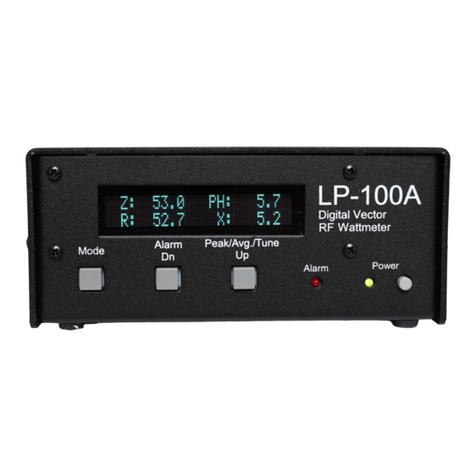
TelePost LP-100 User manual

1
LP-100
Digital Vector
HFWattmeter
Operating &
AssemblyManual
June,2006
TelePost Incorporated
Rev. B2

2
Compliance Statements…
FederalCommunicationsCommission
Statement(USA)
Thisdevice complieswithPart15 oftheFCC Rules. Operation issubjecttothefollowing two
conditions:(1)thisdevice maynotcauseharmfulinterference,and (2)thisdevice mustacceptany
interferencereceived, including interferencethatmaycauseundesiredoperation.
EuropeanUnionDeclaration ofConformity
TelePostInc. declaresthattheproduct:
ProductName:DigitalVectorRFWattmeter
ModelNumber:LP-100
Conformstothefollowing ProductSpecifications:
EN55022:1998Class B
following theprovisionsoftheElectromagneticCompatibilityDirective89/336/EEC,testedandverified
3-17-2006 atFCC accreditedlaboratory.
IndustryCanadaComplianceStatement
CanadaDigitalApparatusEMIStandard
ThisClass Bdigitalapparatusmeetsall therequirementsoftheCanadianInterference-Causing
EquipmentRegulations.
Cetappareil numeriquedelaclasseBrespectetouteslesexigencesdu Reglementsurlematerial
brouilleurdu Canada.
CopyrightandTrademarkDisclosures
LP-100 isatrademarkofTelePostInc. Windows®isaregistered trademarkof Microsoft Corporation.Teflon®isa
registered trademark of E.I. du Pontde Nemoursand Company.PICmicro®isaregistered trademarkof MicroChip
TechnologyInc.
Materialinthisdocument copyrighted ©2006 TelePost Inc. Allrightsreserved.Allfirmwareand softwareused inthe LP-
100, LP-100 VCPand LP-100 Plotprogramscopyrighted ©2004-2006 TelePostInc.Allrightsreserved. MicroCode
Loaderisacopyrighted programfromMecanique, http://www.mecanique.co.uk/.

3
TableofContents
Introduction............................................................................................................4
PartsList.................................................................................................................5
AssemblyInstructions............................................................................................7
InitialCheckout....................................................................................................15
Calibration............................................................................................................17
Operation..............................................................................................................21
CircuitDescription ...............................................................................................24
Schematic............................................................................................................26
Software ...............................................................................................................28
Troubleshooting ...................................................................................................30
SpecificationsandCALTable.............................................................................32
Warranty..............................................................................................................33
AppendixA..........................................................................................................34

4
Introduction
TheLP-100isdesignedasan accurateinstrumentformonitoringstationperformance. It providesanumberofuniquefeaturesnotseen
beforeinahamradiowattmeter.
Themost obviousof theseisthevectordisplay.Thisdisplayshowsthecompleximpedanceoftheloadintwoways. Thetoplineof the
displayshowsimpedanceinpolarform…i.e.,magnitudeandphaseoftheimpedance.Thebottomlineshowstherealandimaginary
componentsofimpedance…i.e., R+jX.Theparametersaredisplayedinarangeof0.1to999.9ohms.Phaseisdisplayedin0.1
degreeincrementsfrom0-180 degrees.
Featuresinclude…
•PLEDdisplaywithbargraphsforpowerandSWR, alongwithnumericalreadout forboth
•ProfessionaldBm/ ReturnLoss display
•50 mWto2500Wwithfourautorangingscales
•Powerdisplayresolution of0.01to1Wdependingon scale
•Frequencycoverageof 1.8-54MHz,withautomaticband-by-bandcompensation
•Z, R,Xdisplayfrom0-999.9ohmseach
•Separatecouplerwith50ohmportsforuncluttereddesktop
•Peak-hold numerical powerreadoutwith"hang"characteristicforpowerandSWR
•SWRaccuracy<.15(5%)fromabout.1Wto2500W, <.10 typical
•Poweraccuracyis5%typical atanyrated powerlevelorfrequencyfrom.5Wto2500Waftercalibration,usableto0.05W
•Canbeeasilymatched in thefield toexternal standardtowithin0.1%on eachband
•Powerdisplayisactual powerdeliveredtotheload(FwdminusRefpower).
•SWRAlarmsystemwithsetpointsforOff, 1.5,2.0.2.5and3.0.
•WindowsfreewareVirtual Control Panel forsoftware/ remotecontrol
•Supportwithin TRX-Managerfordirect remotemonitoring
•Advanced charting capabilityforSWR, RL, Z, R, Xandphaseanglevs.frequency
•Built-inbootloadertoallowforfirmwareupgradestobedownloadedand installed.
•Callsignscreen savertoextend lifeof display
•ConformstoFCCPart 15A&B, ICAS andCEradiated emission limits,tested andverified byaccredited lab
Thismanualwilladdress theassemblyof theLP-100,initialcheckout,calibrationandoperation.You maywishtoread throughthe
circuitdescriptionandstudytheschematicbeforebeginning assemblytofamiliarizeyourselfwiththeproject. Itishighlyrecommended
thatyouthoroughlyread throughthe Assembly section beforeevenunpacking theLP-100kit.

5
PartsList
Pre-installedSMT parts
QTYPart No. Description
4C9,10,12,13 0.01uF50V
2R4,18 Resistor26.71%.25W
2R5, 12 Resistor49.91%.5W
2R6,21 Resistor56.21%.25W
2R9, 27 Resistor56.21%.5W
2R10,20 Resistor4221%.25W
1R24 Resistor1741%.25W
1R30 Resistor1201%.25W
1R33 Resistor32.61%.25W
1R35 Resistor751%.25W
1D8 HSMS-2805 dualSchottky diode
1U1 AD8302
1U9 AD8367
1U10 Gali-74MMIC
1T1 ADP-2-1Transformer
Partstobeinstalled–main chassis
QTYPart No. Description
15 C1,2,5,6,7,11,14,20,22,27,32,33,40,42,43 0.1uF50Vmarked104
2C3,41 10uF50V
1C4 0.33uF50Vmarked334
8C8,21,28,29,30,34,38,39 0.01uF50Vmarked103
7C15,16,17,18,19,31,35 1uF50Vmarked105
2C23,24 0.001marked102
2C25,26 0.002marked202
1C36 330pF50Vmarked331
1D2 Rt.Ang. LEDRed
1D3 Rt.Ang. LEDGreen
1D4 1N4001
1D5 1N4148
1RC1 ribbon cableassembly
2J1,P1 16-pinDILheaderfordisplay
2J2,7 BNC jack,rt. angle
1J3 Powerjack2.5mm
1J4 DB9PCBmount
1J6 DualRCAPCBmount
1JP1 2-pinSILheader&jumper
5L1,2,3,5,7 1mhmoldedchoke
2L4,6 470uHmoldedchoke
1Q1 2N4401
1 LCD-1 PLEDdisplay20x2
2R1,13 1M1%1/8wbr-bl-bl-yel-br
3R2,41,42 10k5%1/8wbr-bl-or
2R3,17 390 5%1/4wor-wh-br (changedto1Kafterser.#36)
6R7,11,14,16,34,36 1k5%1/8Wbr-bl-red
1R8 20kpot
1R15 22k5%1/8Wred-red-or
2R19,29 4.75%1/4Wyel-viol-gold
1R22 150k1%1/8Wbr-grn-bl-or-br
2R23,25 10k1%1/8wbr-bl-bl-red-br
1R26 6.34k1%1/8Wblue-or-yel-br-br
1R31 100 5%1/8Wbr-bl-br
1R32 174 1%1/8Wbr-viol-yel-bl-br
1R37 57.61%1/4Wgrn-viol-blue-gold-br(bluebody)
1R39 120 1%1Wbr-red-bl-bl-br(rustcolorbody)
1RL1 OmronG5V-2-H1-DC5

6
PartsListcont’d
QTYPart No. Description
1 S1 CEM-1212CPiezotransducer
3SW1,2, 3 4mm tactileswitch,rt. Angle&keycaps
1T2 ToroidcoreFT37-61
1U2 LM7805
1U3 18F252 PIC
1U4 TLC-271ACP
1 U5 MAX6225BEPA
1U6 MAX232N
1U7 LM34DZ
1 U8 MCP3304
1Y1 Resonator10 MHz
1PwrCable
1Enclosure Main
1PCB Main
1Heatsink for7805
2ICSocket 8-pin
2ICSocket 16-pin (Inolongeruseasocketfortherelay)
1ICSocket 28-pin
Partstobeinstalled–coupler
QTYPart No. Description
1 Enclosure Coupler
1PCB Coupler
2T1,2 ToroidcoresFT140-61
2UHFConnector SO-239
2BNC Connector UG1094/U
2BNC cable 6'M/M-RG174U
4R3, 4,9,10 75 ohm1%1W(2512SMT)
8R1, 2,5-8,11,12 301 ohm1%1W(2512SMT)
2Nylonbushings Onewith3/16”hole, onewith¼”hole
6AdhesiveTeflon®tape 2 long and 4shortpieces
1TerminalStrip 2lug terminalstrip
1AdhesiveLabel CouplerTop Label
Partstobeinstalled–hardware
QTYPart No. Description
16 4-40x3/16”machinescrews-black
13 4-40nuts–9large,4small
84-40x¼”threadedstandoffs
14-40x1.5”threadedstandoff
6#4 self-tappingscrews–(1)¼”,(5)3/8”–black
14 #4 self-tappingscrews–¼”–plated
15 #4 lockwashers
10 4-40x3/8”machinescrews(forSO-239sandDB-9)startingwithser.#71
5 4-40x1/4”machinescrews(remainingcouplerscrewsandU2heatsink)
8RubberFeet (4)squareforcontroller,(4)roundforcoupler
1#4 SolderLug
1#20 wireforcouplerxfmrs (2)45”lengths
1 #28 wireforcontrollerxfmr (2)6”lengths
1RG-142B/UTeflon®coax (1)2”length
1RG-316UTeflon®coax (1)2”length
1 .25”pieceof shrinkwraptubing
You shouldcheck allpartsbeforestarting toallowyou tostartthe process ofobtaining replacement partsassoon as
possible. Itisalsoagood idea tosort the partsinadvance…egg cartonsarehandyforthis(passivepartsonly). Notethat
the mixof hardwarehaschanged alittleovertime.Thiswasdone inpart tomakesurethatthe screwsforthe long
standoffpostinthe couplerdon’t bottomout.

7
Assembly
Overview
BelowisapartslayoutofthemainPCB.Thesemarkingsmatchthesilk-screening onthePCB, butarerepeatedhereforclarity. You
can alsocrossoutthepartsonthisgraphicastheyareinstalled. Notethatseveralcomponentswithmarkingson theboardarenot
includedinthefinalproduct,namely…C37, C44,C45,R28, L8and J8.J8willbeprovidedaspartof apossiblefutureexternalanalog
meterdisplayoption.Also,therearetwoartworkmistakesontheboard.OnerequirestheadditionofajumperfromU4pin7topin8.
Theotherrequiresthereversalof U7.
AlloftheSMTcomponentsarepre-installedonthisboardforyourconvenience. SMTpartsaresuppliedwherevernecessaryfor
performanceoravailablilityreasons. CAUTION:Beverycarefulhandlingthisboardtoavoiddamagetotheinstalledparts.Anti-static
measuresarehighlyrecommended,suchasuseof ananti-staticmat,groundedsolderingironandwrist band.
Atthispoint,it wouldbeverysmarttoinspect allthesolderpadsforanyproblems, especiallyforearlyserialnumbers.Asof thiswriting,
I haveassembled(8)boardswithout aproblem,butI had acustomeremailmewithapictureofapairofbadpadsonU4thatweren’t
fullyetchedthrough and asaresult thepadshadabridgetoground.Startingat serial#0027Istartedvisuallyinspectingalltheboards
beforeshipping.Iwouldrecommendthebuilderdoasecond inspectionaswell.Bettersafethansorry.
Irecommendapproachingassemblyinthefollowingorder…
Install allICsockets
Install resistors
Install capacitors
Install connectorsand switches
Install 7805regulator
Install chokesselectively

8
Assemblycont’d
Thisallowstheboardtoremainflat duringmostoftheconstruction.Followingthisorderwill alsofacilitateinitialcheckout.Thechokes
will beselectivelyinstalledtoallowforcheckoutof varioussectionsofthecircuit.
Checkout will followthisorder…
Verifyproper+5vdcbeforepoweringanydevices
Install L2, PICandPLEDandcheckdisplayforproperPICoperation
Install L1, L3,U5,U7and U8andverifyproperoperationofADC
Install L5andU4andverifyproperpowerdetection
Install L7andverifyproperfrequency counteroperation
Install U6and verifyproperserialportoperation
Theabovechecks willrequireonlyaDVMand theCalibration screensexcept forthepowerdisplaycheck.Tocheck thepowerdisplay,
you will needatransmitterandcompletedcoupler. I will list expectedcurrentdraininredateachstepsothat youcan verifythat
nothingisshortedineachsection.
TocalibratethepowerreadingsoftheLP-100willrequireaminimumofanaccurate50-ohmdummyload and ameanstomeasurerf
voltage. ACantenna typeofloadisnot generallyagood choice. Thedummyloadwillneedadiodepeakdetectoroutputoryouwill
needacalibratedoscilloscopetomeasurep-prfvoltageacrosstheload.Analternativewouldbeanaccuratereferencewattmeter.
Tocalibratetheimpedancegainandphasedetectorsyouwillalsoneeda25or75-100 ohmdummyload.Thiscanbeeasilymadeup
outofinexpensive3W,5%metaloxideresistors,suchasusedinmyLP-200 ortheElecraft DL-1.Thiscalibration canbedonewithas
littleas1Wofpower.
Alternatively,youcanuseapairof50 ohmdummyloadswithcoaxadapterstoallowthemtobeparalleledtoprovide25 ohms.SWR
calibrationrequiressettingoffsetandslopeadjustmentsfortheAD8302gaindetector.Calibration oftheAD8302phasedetector
requiresadelaylineofknownelectricallength. Youcangetprettyclosebyusing ahighqualitypieceof polydielectricRG-58,and
calculatetheelectricallengthindegreesusingthefollowingformula…
Phase=(360*L*F)/(984*VF)
WhereDelayisindegrees, Lisinfeet and FinMHz. VFwouldbe0.66forpolydielectric.Anyconvenientlengthofabout5-10’is
acceptable,whichwouldprovideadelayof~39to78degreesat 14MHz. Youwill findmoreaboutcalibration inthe Calibration
section.I amcontemplatinganinexpensivecalibration kitinthe$25 range,whichwouldincludeaswitchabledummyload PCBand
pre-cutdelayline.IwillalsocalibrateanyassembledLP-100kitfree ofchargeif you willpayround-tripshippingtome.
You willneedthefollowingtoolstocompleteassembly…
30-60Wadjustablesoldering iron
60/40alloysolder….020”diameterrecommendedforthermalpads
Needle-nosepliers
Wirecutters
SmallPhilipshead screwdriver
Razorknife
DigitalMultimeter
NOTE:TheLP-100iswhatIwouldcall anintermediatelevelkit. Ifcareistaken,you shouldhavenodifficultybuildingit. Iwouldpegthe
assemblytimeat about8hourstotal,alongwithsomereadingthrough themanualinadvance, and sometimeforcalibration.Takeyour
time, and double-check yourwork.Itissomewhatdifficulttocleanlyremoveincorrectpartswhichhavethermalgroundpadsonthem.I
foundinthemanyboardsI haveassembledthatthethermalpadswillaccept solderwellifyouplacethetipoftheironatthejunctionof
thepad andwire. Extraheat mayberequiredonthesepads,however.Iplantoeliminatethethermalpadsonthetopoftheboardand
add moreviastocompensateonfutureboards.

9
Assemblycont’d
Step-by-step assemblyinstructionsformainboard.
Belowisapictureof theassembledPCB.TheSMTpartscomepre-installed.
Itisrecommendedthat you print thismanualtoallowforeasy referencewhilebuilding,andtoallowyou tocheck offthestepsasyou
completethem. Therewillalsobeatableofcalibrationvaluesyou canenterasyoudothecalibration. Thiswill enableyoutoreturnto
theoriginalsettingsshouldyouneedtointhefuture.
Makesureyourworkareaisstatic-free toavoiddamagetothepre-installedSMTparts.Itisalsoadvisabletowearananti-staticwrist
band.Refertothepartsplacement graphiconpage6forquestionsregardingpartsplacement. Youcanzoomintothepdfversionof
thisdocumentforeasierpartsidentificationifneeded.
qInstall all IC(and relay)sockets, keeping theboardflat asyou gotoavoidgaps. AddajumperwirefromU4pin7toU4pin8atthis
time. Thiswireneedstobeinsulatedfromground.
qInstall resistors. Toavoidmessiness whentrimmingleads,Iwoulddo about 6at atime.Ifyouareunsureofthecolorsusedby
someofthemanufacturersforthecolorcode,measurethevaluewithaDMM.
qInstall all .01uFcaps(marked103).
qInstall all .1uFcaps(marked104).Thisshouldbedoneinat leasttwobatches.
qInstall remainingcaps,leaving the10uFcapsforlast. Observepolarityonelectrolytics. Youmayhavetoformtheleadsofthe1
uFcapstofit thesmallspacingoftheholes. Also,somekitsmaybesuppliedwithelectrolyticsforthe1uFcaps.Refertothe
component placementguideforproperpolaritysinceitisnot markedonthesilk-screen.

10
Assemblycont’d
qInstall miscellaneouspartssuchasresonator,Piezotransducer,etc. NOTE:Removetheprotectivecovering onthetransducer
beforeusing.Also, the“+”lead goestothesidewiththejumper,pertheplacement guide.Donotinstallchokesyet.
qInstall connectorsandswitches. Youwill probablyhavetopropsectionsoftheboarduptoensurethatthepartsareflushwiththe
board.Installtheheaderon thePLEDPCB. Theheaderisinstalledon thebacksideofthePLEDPCBwiththelongpinspointing
awayfromtheboard.
qInstall 7805regulator.Attachheatsinktotheregulatorbeforeinstallingon PCB,using 4-40x¼”” machinescrewandsmallhexnut.
qInstall T2.Thisisatoroidxfmr.It ismadeupof 10bifilarturnsofthe#28 enameledwirewoundonaFT37-61core.Bifilarmeans
that thetwowiresarewound asapair.See diagramaboveforwiring. Note: Thedrawing isrepresentational,itdoesnotshowthe
actualnumberofturns. Aturnisdefinedasapassthrough thecenterofthecore. Useanohmmetertoverifythecorrect wiring.
You willwindupwiththree leads, whichwill beinsertedintothethree holesindicatedonthesilk-screen. Thelead withtwowires
goestothecenterholeinthePCB.Makesurethattheenamelisremovedfromthenleadsbeforesolderingtoensuregood
contact.
qInstall L4andL6.Theremainingchokeswillbeinstalledaspartoftheinitialcheckoutoftheboard,inordertoenablepoweringup
ofcircuitsindividually.
qThejumpersforthePTT connectorcan bewirednow.Thenormalwiringisshownonthecomponent placementdiagramatthe
beginningofthischapter,andbelow.Thisprovidesforanormallyclosedconnection betweenthecenterconductorsofthetwo
RCAconnectors. Thiswillworkformost rig/ampcombinations.FormoreoptionsforPTTwiring,check out theSteppIRTuning
Relaysectionof mywebpage.
qAttachtheDB-9connectortothePCBusing4-40x3/8”screwsand smallhexnuts.
qYou caninstall RL1atthistime.Thecorrectpositioningiswiththetwoseparatedpinstowardthebackoftheboard,next tothe
snubberdiode,D5.Iusedtosupplyasocketforthis, buthavedecidedthatthere’sreallyno needforit, andthere’sariskofthe
relayworkinglooseduringshipment.

11
Assemblycont’d
Initialcheckoutofmainboard.
qStep1.Makesurethatyourbenchisclean andthePCBisnotsitting on anycutoffcomponentleads.Connectsuppliedpower
cabletoasupplyof12-15VDC. Thedashedwhitelead on thesuppliedpowercableisthe+lead (centerpin). UsingyourDMM,
check for5.0VDC atpin3of U2.Thevoltageshouldbewithin0.25Vof5.0VDC. ~7 mA.Note: Allcurrentreadingsarewiththe
new1Kresistorsinstalledinstead of390 ohmfortheLEDseriesresistors. Theywillbeabout10 mAhigherwiththe390s.
qRemovepowerand installL2,U7,Y1andthePIC. Rememberthat thesilkscreenisbackwardsforU7. Temporarilyconnectthe
PLEDdisplay. Becarefultomakesurethereisnothingonyourbenchwhichcouldshortout anythingonthePLEDPCB. The
ribbon cableshouldbeorientedasshownintheinteriorphotobelow. Makesurethat theribbonconnectorsarecenteredon the
headersatbothends.
qStep2.Powertheboardupagain,andverifythatyouareseeing the“splash”screenwithversionandcopyright information,
followedbythemainLP-100 screen. Thescreenshouldlooklikethescreenon thephotoatthetopofthe“Operation”sectionof
thismanual. You mayhavetoplaywithR8,thePLEDbrightness pottosee this. Ifyoudon’t see thedisplay, see the
troubleshootingsection.Thepropersettingforthebrightnesspotisjustatthepointwherethedisplayreachesmaximum
brightness. Thiswillensurethatthebrightness dropstotheproperlevelwhenthefirststepofthescreensavertimerisreached. A
fineradjustmentcanbemadeafterthescreen-saverstarts.ThecorrectvoltageforthePLEDatthejunctionofR8andR15is3.0V
atfullbrightness, approx.2.4Vinthescreensavermode. ~35 mA
qStep3.InstallL1,L3, U5,andU8. ~82mA.TemporarilyentertheCalibratemodebybrieflypressingtheModeandAlarmbuttons
almost simultaneously. TheModebutton shouldbepressedslightlyahead oftheAlarmbutton. Youshouldnowsee thefirst
Calibratescreen, called“Offset”. OnceintheCalibratemode,presstheModebuttonrepeatedlyuntilyougettothe“Reference”
screen. You shouldsee something similartothefollowing. ThisscreenshowsthereferencevoltagegeneratedbyU1(the
gain/phasedetector),theReceivedSignalStrengthIndicatorvoltagefromU9(theAGCchip)andtemperatureindegreesFand C
(fromthetempsensor, U7).
qStep4.InstallL5,L7, U4andU6andcheck thecurrent. ~160 mA. Ifalliswell, settheboardasideuntil thecouplerassemblyis
completedtoallowcheckoutofthepowerdetectorcircuitand frequency counter.

12
Assemblycont’d
Step-by-step assemblyinstructionsfordirectional coupler.
Refertothedrawingandpicturesduringassemblyofthecoupler.Thesepicturesarecourtesy of Stan,W5EWA.Constructionof the
couplerconsistsofonlyafewsteps. Themaincomponentsarethetransmissionline,toroidaltransformersandtheattenuatorPCB.
Themostcriticalstepisthewindingof thetransformers. Theyarewoundwith26turnseachof#20enameledwire. Thecoresare
wound inoppositedirections, i.e.theyshouldbemirrorimagesofeachother.Thewindingsshouldbeevenlyspacedover~60%ofthe
core, asshownlater.Thecoresaresupportedbynylonbushings,whichareinsertedintothecorecentersafterwinding.Ifthewiresare
wound tightly,thecoresshouldfit snugly,butshouldnothavetobeforced.Thecoresshouldbewound byhand, don’tuseanytoolson
thecoresorwiresastheymaybreak.
ThebushingwiththesmallerholeismountedbetweentheSO-239connectors,andsupportedbytheRG-142Teflon®coax. Thispiece
ofcoaxformstheprimarywindingofthecurrentsampling transformer.Theothertransformerissupportedbyalong standoff which
formstheprimaryofthevoltagesamplingtransformer.Oneend ofthisstandoff isgrounded, andtheotherconnectstotheattenuator
PCB. Thisstandoffalsoincludesawrapof Teflon®plumberstapetoallowatightfit.Thetransformersecondariesarewiredasshown
inthedrawing.Itisimportantthatthecoresbepositionedasshown,andthewiresberoutedasshown.Improperroutingorcore
orientation willaffectperformance,especiallyabove30MHz.
qInstall thetwoSO-239UHFconnectorsusing 4-40x3/8”machinescrews, #4lockwashersand large#4 hexnutsfor7of the
mounting holes.Theremaininghole, uses4-40x3/8”hardwareandasolderlugasshown.Thesoldercupson theSO-239s
shouldbefacingupward.
qSoldertwoshortpigtailsabout 1.5”longintothecenterpinofthetwoBNCs.Youcanusecut endsfromotherpartsforthis.Install
thetwoBNC connectorsusing thesuppliedspecialhardware,includingsolderlugs,asshown.

13
Assemblycont’d
qPreparethetwopiecesofcoaxasshowninthediagram.Makesurethattheshieldwiresdon’tshortouttothecenterconductoron
eitherend. RG-142isdoublesilvershielded.Youmayfindit easiertoremovetheoutershieldtokeepthetwistedshield
connectionmoreflexibleand easiertoworkwith.Slipashortpieceof heatshrinktubingovertheshieldandheat withaheatgun or
hairdryer.Analternative,showninW5EWA’spicsabove,istocuttheshieldshort,and thenwrap ashort pigtailof wirearoundit.
qWind26turnsof#20enameledwireon eachoftheFT140-61 cores.. Thecoreswillbewoundinoppositedirections,sothatthe
finishedtoroidswillbemirrorimagesofeachother.Awinding isdefinedasthewirepassing throughthecenterofthecore. If you
countwindingson theoutsideedgeofthecore,yourcount will beoneshortoftheactualnumberof turns.Mis-countingbyoneturn
will giveyou apowerreadingerrorof8%,andcauseotherproblemsaswell.Thecurrentsamplingxfmrisinstalledbetweenthe
SO-239 connectors, andwill besupportedbytheshortpieceof Teflon®coax. Thevoltagesamplingxfmrissupportedbythelong
standoff.Leavepigtailsasshownonthewiresfornow,andscrapetheenameloff theendsof theshortleads.Arazoror
sandpaperisgoodforthis.Theshortonesare1”long, andthelong oneis3”long. Windthewiretightly. Useyourfingerstokeep
thewindingsformed closetothecoresontheinside.

14
Assemblycont’d
qBeforeslippingthenylonbushingsintothewoundcores,takethetwolongpiecesof Teflon®tape, peelthepaperoffofthe
adhesiveside, andwrapeachofthenylonbushingswiththeTeflon®tape. Thentakethemediumpieces,removethepaper,and
sticktheminthecoresbetweenthewindings, withthethickeroneagainstthecore. Thiswillmakeforatightfit insidethetoroid
cores,andwillalsoservetokeepthewindingsproperlypositionedaroundthecores.Beforesliding thecoresinplace, makesure
that theinsideofthewindingsisflatagainstthecores. Becarefulwhenpushing thecoresinplacenottodislodgetheTeflon®
tape. See thepicturebelow…
qSolderthe12SMTresistorsontotheattenuatorboardasshown. Don’t beafraidofthis.TheseareVERYbigpartsasSMTgoes.
Theresistorvaluesareprintedontheresistors.Useafinetiponthesolderingiron, andtinONEofthePCBpadsforeachresistor
withasmall amount ofsolderbeforeattemptingtosoldertheresistors.Holdtheresistorsinplacewithatweezers, andapplyalittle
heat totheedgebetweeneachpad andtheboarduntil thesolderflowsbetweentheresistorandpad. It ishelpfultoslidethe
resistoroverthepadasit meltsontothesolderdrop,sothattheotherend exposesalittleofthepad ontheotherside. Solderthe
othersideinplacebyapplyingheatandsoldertotheedgewheretheresistorsitsonthepad. Thengoback tothetackedpad and
touchupifnecessary.Applyingalittlefluxtotheboardahead oftimewillhelptoholdthepartsinplaceandaidinsolderflow.To
verifytheproperinstallationoftheresistors,usean ohmmetertocheck theresistanceofeachbarestriplineconnectiontoground.
Themounting holeisgrounded, aswellasthelong stripalongthetopedge. Eachpointshouldbeabout83-84ohms.Ifnot,
check yoursoldering.
qInstall thePCBontothesideofthecouplerabovetheBNCsasshown. Theboardmountswiththeholenearthebottomedge.
Bend and solderthepigtailsfromtheBNCstothetwostriplinesnearthemountinghole.

15
Assemblycont’d
qSolderonetheshortpieceof RG-316Upreparedearliertothesolderterminalonthebottomofthecoupler,withthecoaxshield
connectingtothegroundedlug, and thecentertothelug that connectstothecurrentsamplingxfmr.
qSolderthecenterconductorfromtheotherend ofthecoaxtotheremainingPCBstriplinepad,andtheshieldtotheground lugon
thecenter-most BNC.
qSlidethecurrentsamplingtransformerovertheshort pieceofRG-142asshowninthediagrams,beingcarefultoposition the
windingsandthecoaxshieldasshown.Thisisatightfit, butifyoutakeyourtimeandrotatethecoaxasyoupress itintoplace,
you shouldn’thaveanytrouble.Thereseemstobealittlevariationinthediameterof theRG-142,soyou mayfind thatyou needto
filetheinsideof thebushingalittletoallowagoodfit.Thiscanbedonewithasmallrattailfileorarolledpieceofsandpaper.
qBeforesolderingthecoaxintothesoldercupsontheSO-239s,verifythatthesidesofthecasebottomareparallel.Thisis
importantsothatthereisminimaltensiononthecoaxwhenthescrewsareinstalledtoholdthecasehalvestogether. Thexfmr
shouldbeorientedlevelwiththewindingsfacingupbeforesoldering. SolderthecoaxintotheSO-239 connectors,andtheshield
wiretothesolderlugontheXMTRconnector. Cutthewirefromtheoutsideleftofthetransformersecondarytolengthandsolderit
tothelug ontheXMTRconnector.
qCut and solderthewirecomingfromtheinsiderightsideofthexfmr totheinsulatedlugonthesolderterminal.
qSlidethevoltagesamplingxfmroverthelong threadedstandoff.Ihavewrappedthestandoff withtwolayersofplumbersTeflon®
tape. Pushthexfmr overtheend withthetapeon it untilitprotrudesabout ½”.Holdtheassemblyup tothechassistomakesure
that thexfmr iscenteredbetweenthesides. Lookingattheinsidepictureofthecompletedcoupler, makesuretheshortsideofthe
standoff protrudesfromthesideofthexfmrwiththeshortlead.Trimtheexcess tapefromtheend ofthestandoff.
qTakeasmallpigtail ofabout2”lengthand installitontheend oftheassemblywhichfacestheattenuatorboard.Use4-40x1/4”
hardware.
qAttachtheassemblytothesideofthecouplerusing4-40 x¼” hardware. Thepigtail shouldbefacingthePCB.Itisimportantthat
thisassemblybeattachedfirmlyoryou willsee erraticoperation.
qPrepareand soldertheshort end ofthetoroidwinding sothatitconnectstothesolderlugon theright-mostBNC.If thecoreis
mountedcorrectly,thiswireshouldcomeofftheright sideofthecorefromtheinside.Solderthepigtailfromthestandofftothe
striplinepad on theend ofthePCB.
qThelongwirecomingofftheoutsideleftsideof thecoregoestotheoutput SO-239asshown.Scrapetheend ofthewireand form
aloop togoaround theSO-239 centerconductor. Thewireshouldfollowthepathshown.Forbestphaseaccuracyat50MHz, a
littlecouplingtothecurrent xfmrsecondaryisdesirable. BecarefulnottooverheattheSO-239 centerconductorwhensoldering
thewire.
qMakesurethatall connectionsaresolderedwell,andthat thecoresarelevelandcenteredbetweenthecasewalls. Slipthetop on
and attachwith(14)4-40x¼”sheetmetalscrews.
qClean andwipethetopofthecoupler.Carefullylineupthetoplabelandapplystartingatoneend andsmoothingasyougoto
prevent theformation ofbubbles.
Final Checkoutand Assembly
Beforegoingthrough theCALscreens, itisnecessarytoverifythattheremainingbasiccircuitsareworking.PoweruptheLP-100,and
verifythat thecurrentdrawiscorrect. 160mA
ConnecttheCurrentandVoltageportsof thecontrollerandcouplertogetherusing thesupplied6’coaxcables. Youmaywanttobundle
thecablesusingelectricaltapetomakeforaneaterinstallation,butit wouldbesmarttomarkoneofthecablessoasnottogetthem
confusedatalaterdate, otherwise25 ohmswill be100ohms!
Connect a50ohmdummyloadtotheLOADport. SelecttheFast modeforthedisplay(lowercase“w”), and applyasmallamountof
power. ThePowerand SWRbargraphsshoulddeflectupward, andthenumericalreadoutsshoulddisplayanumberreasonablyclose
totheexpectedvalue.Switchtothevectordisplay,andyoushouldsee valuescloseto50 ohmsforZandR,andclosetozerofor
phaseand X.
Next, enterCALmodeandscroll totheFinescreen. Youshouldsee thebandindicatedinthelowerleft cornerduringtransmission.
Thisshouldmatchthebandyouaretransmitting on.TheBandindicatorshouldremainonthelast usedbandaftertransmission.

16
Assemblycont’d
UsingtheAlarmSet button, settheAlarmfor“1.5”.Removethedummyload andtransmitintothecouplerat lowpower.TheRedAlarm
LEDshouldlighton thefrontpanel,andtherelayshouldclick. IfyouhaveJP1inplace,thePiezotransducershouldalsosound.Note:
thetransducerwillsoundprettyloud sinceit’snotinsideacaseatthispoint.Reconnectingthedummyloadwillcancelthealarmaftera
second orso. You can double-check thePTT connectionswithanohmmeteratthistime. Thecenterconuctorsof theRCAconnectors
whouldbenormallyshortedtogether,andopenwiththealarm.
You arenowreadytoinstallthecontrollerboardinthecase. First, installthe4-40x¼” threadedstandoffsonthebottomofthecase
using4-40 x¼”blackmachinescrews.Next, slidetheboardintotherearholesasyoudrop thefrontdowntowardthebottom.Be
carefulnottoscrapethebottomoftheboardonthefrontpanelasyouslideit. You mayhavetobend theLEDsbackalittletoallowthe
boardtoslidedown,andslightlypress theswitchesaswell.
Oncetheboardisinplace,alignthefrontholeswiththeswitchesandLEDs,andscrewtheboarddownwithfourmore4-40 x¼” black
screws.Theswitchcapswillbeinstalledaftercalibration,incaseaproblemshowsupthatrequiresremovalof theboardfromthecase.
Thecapscan bescratchedduringremovaliftheyareinstalled.
Install thefourremaining4-40x¼”standoffsonthefrontofthePLEDPCB,usingfour4-40 x¼”blackmachinescrews,andtighten.
MountthePLEDPCBtothefront using theremainingblackmachinescrews, andinstalltheribboncablebetweenthetwoPCBsas
showninthepicture.Again, makesurethattheribbon jacklinesupproperlywiththeheaderpins. Don’tforgettoremovetheprotective
filmfromthePLEDdisplaysurfacebeforemounting. Thetopcoverwill beinstalledaftercalibration.
Connections…
Power: 12-16VDC,centerpin+.Thelead withthewhitestripeonthesuppliedcableis+
PTT: LoopthePTTbetweenyouramplifierandrigthrough theLP-100usingRCAconnectors
RS-232:Connectstocomputer.
Current/Voltage:ConnecttocorrespondingjacksonthecouplerusingsuppliedRG-174Ucables.

17
Calibration
EntertheCalibratemodeagainbyhittingtheModeand Alarm buttonsinanoverlappingsequenceasdescribedintheInitialCheckout
section. Belowyouwillsee apictureofeachCalibratescreenalong withabriefsynopsisofwhatitdoesandwhatthecontrolsadjust.
TheModebuttoncyclesthroughthevariousCalibratescreens, andtheDn/Upbuttonsallowadjustment oftheCalibration constantfor
thatscreen.
Allowsadjustmentoftheaccuracyoftheop-ampdetectorandADC toprovidecorrect conversion valuesat
lowpowerlevels. Thisadjustmentismadebytransmitting at alowpowersuchas1W, andmatchingthe
voltageon thedisplaywiththevoltageatU8pin1asread onaDMM.
AdjustsoverallpoweraccuracyoftheLP-100. Thisadjustmentaffectsallfrequenciesequally, and ismade
bycomparing theLP-100powerreadingwithan accuratereference. Acceptablereferencemeasurement
devicescan beinexpensivelymade,andwill bedescribed later.
Sameasabove,but adjuststhedisplayedpowerreadingon aband-by-band basis. Thebuilt-infrequency
counterdetectsthebandyou’reon, andstorestheCALconstantforeachbandautomaticallyfor12bands
from160mthrough4m.Thecounterworksfrom50 mWto2500W.
Thisadjustmentisused tocalibratethezeropoint (oroffset)ofthemagnitudedetectorforproperdisplay.It
ismadebytransmittingintoan accurate50ohmdummyload,andsettingthescreen toread50.0.If your
load isknowntobecloseto50ohms,butnotexactly,adjustforthevaluethatmatchesyourload. There
aresettingsforHFandVHF. TheproperCALconstant isautomaticallyselectedwhen you transmit.
SimilartotheZeroscreen. Thisadjustmenthoweverisdonewithavalueremovedfrom50ohms.25 or75-
100ohmsaregood choices. Theadjustment correctstheslope(orgain)ofthemagnitudedetector. There
isalittleinteractionbetweenthesetwocontrols, soyouneedtotouchupZeroafteradjustingSlope.
Thisadjustmentisused tocalibratethezeropoint forphasedetector. It issimplydonetransmittingintoa
highquality50ohmdummyload. Thecontrolsarethenadjusted sothat thedisplaycorrectlyshowszero
degrees. LaterfirmwareversionschangedtheTrimvaluetothree digits.
Thisadjustmentisused tocalibratetheslopeofthephasedetector. Itissimplydonebyinsertingalinewith
knowndelayintotheCurrentinputoftheLP-100, andtransmittingintoahighquality50ohmdummyload.
The controlsarethen adjusted sothat thedisplaycorrectlyshowsthelinedelay. IfcoaxofknownVelocity
Factorisused, thelinelengthindegreescanbesimplycalculated.
Thisscreenisused tomatchthereadingsofthelowpowerandhighpowerADC inputs.It isdoneata
powerlevelbelow320W, whichisthepoint at whichthelowpowerinputreachesmaximum.Itspurposeis
toallowcompensatingforanyerrorinthe1%precisiondividerpartsused inthehighpowerinput.
Referencescreen.Displaysthereferencevoltagefromthegain/phasedetector,aswellastheRSSI
voltage(ReceivedSignal StrengthIndicator) fromtheAGCchipused in thefrequencycounterpreamp.
Thisvoltageisproportionaltothelog oftheRFinput powertotheLP-100. Thescreen alsoshows
temperatureinDegF &C. Therearenoadjustmentsforthisscreen,it isused fortroubleshootingpurposes
only.
TheTrimvalueon thebottomdisplaylineistheCALconstantyouareadjusting,andthevalue(s)totheleftofit aretheparameter
being measured. Asyou changetheTrimvaluewiththeDn/Upbuttons,theparameterwillchangevalue.
NOTE:Beforeproceeding toCalibration,check theLP-100Updatepage, www.telepostinc.com/LP-100-Update, forthelatestfirmware
revision. Ifit’slaterthanyours, you shoulddo theupdatebeforecalibrating. Mostfirmwarerevisionswill notaffectcalibrationunless you
purposelyselect“ProgramData”intheOptionsmenuintheMCLoaderprogrammingsoftware. Check theSoftwaresectionof this
manualformoreinformation. Youcan download MCLoaderontheUpdatepage,aswellasthelatest firmwarehexfile. Thereisa
summaryofupdatechangeslistedalong withthefiles. Thisisasimpleprocess, and offersagreat waytokeepyourLP-100current
through multiplefree updates.

18
Calibration Cont’d
InitialCalibration
ThefirsttestrequiresonlyaDMM,andissimplyaccomplishedbytransmittingatalowpowerlevel…approximately1-5W,and
measuringthevoltageatU8pin1.WhileintheCAL>Offset screen, adjusttheDn/Upbuttonstomatchthemeterreadingofyour
DMM. JottheTrimconstant downforfuturereference. Thereisapageattheend ofthismanualtomakethateasy. NOTE:Normaluse
oftheLP-100, includingtheflashprogrammingofanewfirmwareversion, will not disturbthesavedCALconstantsunless you havethe
MCLoadersoftwareset uptowrite“ProgramData”.Jottingthevaluesdownwill allowyoutoreturntoyouroriginalsettingsincaseyou
accidentallychangeavaluebymistake.
Thesecond screenallowsfortheadjustmentofMasterpowersensitivity.Thisvaluewillnormallybeleftat1.000unless forsome
reason theFinecalibrationvaluesareunabletoallowyoutoreachthepropersettings.BoththeMasterandFinepoweradjustments
havearangeof+/-10%in.1%increments.
TheFinesensitivityadjustment ismadewhiletransmittingintotheLP-100.Theadjustmentscannotbemadeunless you are
transmitting,sincetheCALmemoriesareindexedtofrequency, andthecounterneedsan inputtosupplythecurrentfrequency. NOTE:
thelastusedfrequency isdisplayedwhennot transmitting.
Beforeadjustingeitheroftheseparameters,it isnecessarytoprovideanaccuratemeansofmeasuringpowerthatisindependent of
theLP-100.ThesimplestapproachtothisistoborrowahighqualitymeterlikeaBirdorAlphatouseasareference, andconnectit
betweentheLP-100anddummyload withaUHFmale-maleadapter.
Thesimplest, andprobablymostaccuratemethodfordoingthiswithsimpletoolsistouseahighqualitydummyload withadiodepeak
voltagedetectorandDMM. Hereisthesetup…
Thefollowingformulacan beusedtodeterminepower.
P(watts)=(Vpk+.25)*(Vpk+.25)/100
Thediodeisa1N5711 Schottkydiode,andthecapis.01uF.Aconvenientpowerleveltouseis10W,asitiswithinthePIVspecs ofthe
1N5711.10Wproducesapeakvoltageof~31Vacross a50ohmload.Thediodewillhandleupto40W, but I haveonlytestedthe
circuitforaccuracyat10W. ThevoltageneedstobemeasuredbyahighimpedanceDMM withgood accuracy. MostqualityDMMs
have>1meginputimpedance,and manyhave>10meg input impedance.
Theaccuracyofthissetupwillmainlyberelatedtothequalityoftheload.Ifthedummyloaderroris5%, thenthepowercalculationwill
beroughly5%off. Theactualdiodedrop willverylikelybewithinabout.2Voftheassumed valueintheformula,foravoltageerrorof
under1%at100V.Youcanroughlyguess attheRFresistanceofyourdummyloadbymeasuringitat DCwithaDMM,althoughthat
methodwillmostlikelybeinaccurateat50 MHz,and probablyat28 MHzaswell. Makesureyoumeasuretheresistancewiththeload
at operatingtemperature.Also,allconnectingcables/adaptersneedtobeasshortaspossible.

19
Calibration Cont’d
Ifyoudon’t haveaccess tothesemethods,youcansend yourcompletedLP-100 backtomeforcalibrationifyouarewillingtopayfor
returnshippingcosts.
Thefirst stepinpowercalibration istosettheMasterTrimvalue.Thisshouldbedoneon 1.8or3.5MHz. MakesuretheFineTrim
settingforthisband is1.000,thentransmitataknownpowerleveland adjusttheMasterTrimsettingsforthecorrectpowerreading.
ToadjusttheFinepowerconstantsforeachband,simplytransmiton thebandofinterest andadjusttheDn/Upbuttonsforthecorrect
powerreadings.Movethroughallbandsinsequenceuntiltheyhaveallbeenadjusted. You willnoticethat whenyou transmitnow,the
Trimvaluechangesautomaticallybasedon theband.
Thenext seriesofadjustmentscreensareusedtosetup thegain/phasedetectorforproperZ, SWRandRLdisplay.Thefirstofthese
screensistheGainZeroscreen, whichisusedtocenter,or“zero-out”thegaincomparator.A50ohmload isrequiredforthis
adjustment.Simplytransmitonaconvenientbandinthemiddleofthemeter’srange,suchas20m, ataconvenientpowerlevelabove
about2watts. Thedisplayshouldshow50ohms.Ifitdoesnot,theusetheDn/Upbuttonstoadjustthedisplayfor50 ohms.Thevalue
maychangeslightlywithpower, dependingonhowcloseto“typical”yourAD8302is,andshowreducedbutusableaccuracybelow1
watt.
Next, switchto6mif you haveit,andtransmit again.UsetheDn/Upbuttonstosetthevalueto50 ohmson6m.TherearetwoGain
Zeroconstantstoallowfordeviationsat theupperlimitofthecoupler…oneforbelow6mandonefor6m.
Thenext screenistheGainSlopedisplay. Switchbacktothelowerbandforthisadjustment. Thisisusedtoadjusttheslopeorgainof
thegaincomparatorsothatloadsremovedfromthecenter(or50ohms)willdisplayproperly. You can usealoadintherangeof20-25
ohms,oroneintherangeof75-100 ohmsforthisadjustment.Aconvenient valueis25 ohms,whichyoucanobtainbyparallelingtwo
50 ohmdummyloads.Ifyoudon’thavesuchdevices,youcanmakeyourownusingmetaloxidepowerresistorsand aPL-259
connector.5W, 5%metaloxideresistorsareavailableinexpensivelyfromMouserand Digikeyandcanbeusedforthisadjustment.Any
valueintheabovementionedrange,mountedinsideaPL-259shouldsufficetoprovideaload with5%accuracyand a5W-10Wrating
forshortperiods. Youcan measuretheDC resistanceoftheloadasareasonableapproximation oftheRFimpedance.Ifyou makethe
Slopeadjustmentonalowbandsuchas80or40m,thismeasurementshouldsuffice. AdjusttheDn/UpbuttonstomatchyourDC
reading.
ThefinalCALadjustmentsforthegain/phasedetectorarethePhaseZeroandPhaseSlopeadjustments.TheZeroadjustmentisdone
bytransmittingintoahigh qualitydummyloadandsettingtheDn/Upcontrolsforareadingof“0.0”degrees. Makesureyou removethe
paralleleddummyload afterthepreviousstep. Thedisplayisinabsolutevalue,sonegativenumberswill bepositive.Ifyou gotoofar,
thedisplayedphasewill thereforeclimbagain.Thecorrectsettingisasclosetozeroasyou can get, preferablyonthepositiveside,but
thisisn’t critical.
AsmentionedintheOverview, adjustingthePhaseSlopeissimplyamatterofmatchingthereadingtoaknowndelaylinevalue.Again,
theformulafordeterminingdelayindegreesis…
Phase Delay(Degrees)=(360*L*F)/(984*VF)
WhereLisinfeet andFinMHz. VFwouldgenerallybe0.66 forpolyethylenedielectric. FoamdielectricsaregenerallyhaveaVFof
about.80.Check forthecorrectvalueofthecoaxtype/brandyouareusing.Anyconvenientlengthofabout6-10’isacceptable. A6’
lengthwillprovideadelayofnear45degreesat14 MHz. Thisisagoodrangetouse.
InsertthedelaylineintotheCurrentcablebetweenthecontrollerandcoupler,using aBNCbarrelconnector.Besuretoadd thelength
ofthebarrelinyourcalculations. Witha50ohmload, thephaseshouldread closetothecalculatedvalueindegrees. Ifnot, usethe
Dn/Upbuttonstoadjustthereadingtothecorrectvalue.
Again,Iamcontemplatinganinexpensivecalibrationkitinthe$25range, whichwouldincludeaswitchabledummyloadPCBandpre-
cutdelayline.I willalsocalibrateanyassembledLP-100kitfree of chargeifyouwill payround-tripshippingtome.
Thelast screentoadjustistheHi/Loscreen. Thisisusedtomatchthepowerreadingsforthehighandlowpowerranges.Ifyou
transmit atapowerof100W, thetworeadingsshouldroughlymatch.Ifnot,adjusttheDn/Upbuttonstomatchthereadings. TheHi
readinghaslessresolution, soitwilljumparoundalittleand you maynotget anexactmatch. Ifthat’sthecase, erronthehighside.
Log allyourconstantsforfuturereference, and you’redone.

20
Calibration Cont’d
Finaldetails
Ifeverything hascheckedouttothispoint,you cancompletetheassemblyof thecontrollerbyadjusting theLEDsonthefrontpanelto
lineupwiththeholes,andsnap theswitchcapsinplaceontheswitches.
You cannowinstall thecoveronthecontroller. NOTE: Thescrewholenext tothePLEDdisplayrequirestheuseofa4-40x¼”self-
tappingscrewasopposedtotheother5holeswhichusea3/8”screw. Thisisimportanttoavoidshorting ofthePLEDconnector.
Other manuals for LP-100
1
Table of contents
Other TelePost Measuring Instrument manuals

