Telesis XPRESS EP/TLM User manual

XPRESS™ EP /TLM Laser Marking System
Doc. No. 40213 – 1 of 6
System Overview
The XPRESS EP/TLM is an advanced, fiber-coupled diode
end-pumped laser marking system. The laser beam quality and
Q-switched pulse characteristics are optimized for applications
that require high beam quality and stability. This system is a very
good choice for general-purpose laser marking, scribing,
trimming, and other material processing applications.
The XPRESS-series unique L-shaped design features a continuous
wave (CW)/Q-switched Nd:YVO4end-pumped laser with a
remote fiber-coupled diode pumping source. With average diode
life of greater than 20,000 working hours the XPRESS EP offers
the user “best-in-class” reliability.
The robust mechanical and optical design allows the Telesis
XPRESS EP to operate in industrial conditions with respect to
shock, vibration, and dust.
The XPRESS EP/TLM laser marking system offers these
advantages:
•Reliable, long, maintenance-free performance
•Compact size and modular construction
•Remote, fiber-coupled pumping diode
•Exceptional beam quality and stable output power
•Active (thermo-electrical) temperature control of the
laser crystal and pumping diode
•Active AO Q-switching
•Air cooling
•Visible red diode for dry run / positioning
•Large digital display for marker status, settings, and
error condition monitoring
•Standard 115/230VAC operation
•DoD-compliant Unique Identification (UID) marking
System Configuration
The XPRESS EP/TLM basic package consists of the following:
•TLM-Series Laser Controller – contains pumping diode,
RF driver, and other electrical components
•Fiber Optic / Umbilical Assembly
•XPRESS EP Laser Marking Head – contains sealed
resonator, beam expander, turning mirror, galvanometer
assembly, visible red light positioning laser
•Software – Merlin II LS Laser Marking Software
•System Computer – supplied by Telesis or by customer
The modular design allows for major components to be easily
replaced and returned to Telesis if in need of repair.
Laser System Options
•Desktop computer or Notebook computer with powered
cardbus-to-PCI expansion enclosure
•Externally-mounted focus-finder diode
•Tool post w/ manual hand crank for z-axis adjustment
•Pushbutton station (start/abort)
•I/O Options:
TTL via PCI-DIO24 Card (Kit #53920)
Opto-isolated via Merlin DCIO Module (Kit #53928)
TMC090 Controller (for auxiliary axes; additional I/O)
•Programmable X-, Y, or Z-axis (TMC090 required)
•Rotary drive fixture (TMC090 required)
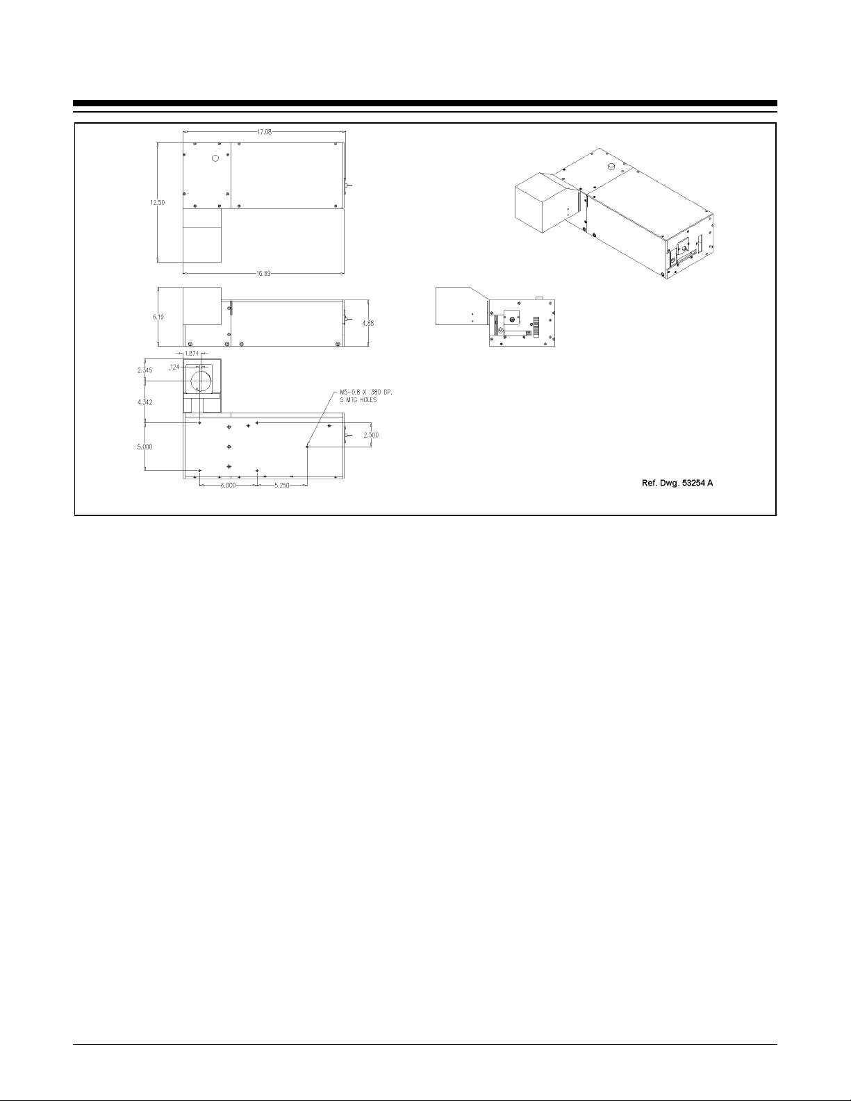
XPRESS EP/TLM Laser Marking System General Arrangment
XPRESS™ EP /TLM Laser Marking System
Doc. No. 40213 – 2 of 6
System Setup
Complete installation procedures are provided in the
XPRESS EP/TLM Installation/Maintenance Manual. The
following procedures are listed for reference only to provide a
general overview of the installation process.
1. Equipment should remain powered down and in OFF
position until mounting is complete.
2. Place computer, monitor, keyboard, and laser controller in
desired location. Locate controller as close as practical to
laser marking head. Standard cable length is 1.75 meters
(5.74 feet) long between the laser marking head and the
laser controller. An optional 4.75-meter (15.58-ft.) fiber
optic cable is also available.
3. Place the laser marking head on selected mounting.
a. Do not bend or kink fiber optic cable. The fiber
optic cable will tolerate approximately 300 mm
(12 in.) diameter bend without damage.
b. Allow a minimum distance of 150 mm (6 in.) at
rear of the laser marking head. This will provide
sufficient room for a proper bend radius of fiber optic
cable.
c. Do not block or obstruct exhaust fan. Note location
of exhaust fan on right side of the laser marking head.
This fan must have adequate clearance to ensure
proper cooling.
4. Mount laser marking head using any three of five factory-
tapped M5-0.8 mounting holes provided.
a. Locate five pre-drilled M5-0.8 mounting holes. The
one nearest the galvanometer output is referred to as
the "origin". All other mounting hole dimensions are
referenced to this hole. Refer to the Mounting and
Dimension Details drawing more information.
b. Telesis recommends using a minimum of three (3)
attach points for mounting the laser marking head,
one of which should be the origin mounting hole.
c. Mounting bolts must not extend into laser marking
head more than 9.5 mm (.38 in.) to avoid
interference with internal components.
d. The leading edge of customer-supplied mounting
fixture should extend no greater than 25.4 mm (1 in.)
from origin mounting hole to allow clearance for
beam output lens.
e. As viewed from front of the laser marking head in
upright position, center of output beam is 11.0287 cm
(4.342 in.) from origin mounting hole.
5. Secure the laser marking head to mounting fixture using
M5-0.80 bolts and lock washers. Do not over tighten bolts.
6. Ensure laser controller power switch (front panel) is OFF.
7. Select proper fuse arrangement, then connect power cable.
8. Connect fiber-optic cable to laser marking head. Connect
remaining cables, as applicable.
9. Refer to XPRESS EP/TLM Operation Supplement for proper
startup procedure. Refer to laser marking system Operation
Manual for complete information on using system software.
XPRESS EP Laser Marking Head Dimensions and Mounting Details

XPRESS™ EP /TLM Laser Marking System
Doc. No. 40213 – 3 of 6
XPRESS EP/TLM System Specifications
Compliance............................CDRH
Laser Type.............................fiber-coupled, diode end-pumped,
Q-switched, Nd:YVO4
Wavelength (laser output)......1,064 nanometers (nm)
CW Average Power ..............7 watts at 1,064 (nm)
Expected Diode Lifetime.......greater than 20,000 hours
Long Term Output
Power Stability ...................less than ± 2%
Max. Power Consumption .....less than 500 watts
Input Power ...........................95 to 250 VAC, 6 amps, 50/60 Hz
single phase
Supply Voltage Fluctuation ...± 10%, maximum; clean ground line
Oper. Environment ................Indoor only; Installation Category II,
Pollution Degree 2 Environment
Oper. Temperature.................18° to 35°C (65° to 95°F)
Recommended Temp.............20° to 25°C (68° to 77°F)
Oper. Relative Humidity........10% to 85% non-condensing
XPRESS EP Laser Marking Head
The XPRESS-series lasers have a unique, space-saving “L”
shaped footprint. Designed for easy maintenance, the galvo head
is mounted at a 90° angle to the laser rail. A heat exhaust fan is
located on the back side of the unit.
The laser marking head encloses the sealed laser resonator, the
beam expander, the turning mirror, the red light dry
run/positioning laser and the galvanometer assembly.
Laser Marking Head Specifications
Dimensions (L x D x H) ........43.38 x 31.75 x 15.72 cm
(17.08 x 12.50 x 6.19 in.)
Mounting Weight..................approx. 13.6 Kg (30 lbs.)
Mounting Holes .....................five factory-tapped M5-0.80
Positioning.............................visible red diode beam (650 nm)
Field Resolution.....................16 bit (65535 data points)
Galvanometer Repeatability ..less than 22 micro radian
Marking Field Size ...............lens-dependent, see chart
Fiber-Optic Cable Length......1.75 m (5.74 ft.) – standard
4.75 m (15.58 ft.) – optional
Cooling ..................................air cooled, active thermo-electric
Marking Field Size
The size of the marking field is dependent on lens type.
See below.
Sealed Laser Resonator
The laser resonator is assembled and sealed in the clean room
environment to prevent optical contamination. The laser resonator
contains an electro-mechanical safety shutter. Under power, the
safety shutter allows 1064nm laser beam to pass through the
galvanometer steering mirrors. If the shutter is closed during
normal operation (or power is removed from the system via a
power off/stop condition) it will inhibit the 1064nm laser beam.
Visible Red Positioning Beam
The laser marking head produces a visible red diode that may be
viewed on the work surface without the need for protective safety
goggles. This provides a safe and convenient aid for laser setup
and part programming. Since the red beam is located after the
shutter, the positioning beam may be used with the shutter opened
or closed. Additionally, the visible red beam may be used with the
lasing beam during the marking cycle. Note that protective
eyewear should always be worn when the laser is in operation.
Flat Field Lens, Final Objective Lens, (F-Theta Lens)
The final object lens is key to the marking performance of the
system. This is the final coated optical lens that the beam will pass
through before it strikes the marking target. This lens is called a
flat field lens because when the beam is focused, the focus lies in a
plane perpendicular to the optical axis of the lens. To protect the
final objective lens from dust and debris, a clear protective cover
is inserted between the work area and the lens.
The following chart outlines the available lenses, the resulting
image field provided by the lens, and the working clearance (in
millimeters and inches).
Lens
Image Field
(mm) (in.)
Working
Clearance
(mm) (in.)
100 mm 65 x 65 2.56 x 2.56 97.0 3.82
160 mm 110 x110 4.33 x 4.33 175.0 6.89
Spot Size (line width)
In all cases, laser marked spot size is dependent on a variety of
factors including lens selection, focus, laser power, and the
material being marked. The following chart is provided for
reference only.
Lens Spot Size (line width)
100 mm 25 microns (.0010 in.)
160 mm 40 microns (.0015 in.)

XPRESS™ EP /TLM Laser Marking System
Doc. No. 40213 – 4 of 6
TLM-Series Laser Controller
The pumping diode is enclosed in the laser controller, while the laser
resonator with the crystal is located in the laser marking head. The
pumping beam from the diode (approx. 808 nm) is delivered through
a fiber optic cable directly into the laser resonator.
The laser controller also contains the active thermo-electrical cooling
system for the pumping diode, the RF driver, galvanometer power
supplies, driver control circuits, appropriate fusing, and a
115/230VAC IEC320 connector, and a front panel control module.
Engineered for the greatest reliability and for ease of maintenance,
the pumping diode within the laser controller is an easily replaceable
sealed module with expected lifetime of greater than 20,000
operating hours.
Operator Control Panel
The front panel includes the system key switch, laser off push
button, manual safety shutter control, function indicators, and LCD
display. The display allows monitoring of the diode current, the
crystal and diode temperatures, system status, and error conditions.
TLM-Series Laser Controller Console
Laser Controller Specifications
Dimensions (W x H x D)....... 42x 14 x 50cm
(16.5 x 5.5 x 19.5 in.)
Surrounding Envelope ........... 50x 14 x 56cm
(19.5 x 5.5 x 22.0in.)
Weight ...................................approx. 10 Kg (22 lbs.)
Cooling ..................................air cooled, active thermo-electric
Fiber Optic Cable Assembly
The fiber optic cable is permanently attached directly to the
pumping diode within the laser controller and cannot be removed.
The standard optical fiber is 1.75 meters (5.74 feet) long. An
optional 4.75-meter (15.58-ft.) fiber optic cable is also available.
System PC
The laser system requires an IBM-compatible computer for
running the Merlin®II LS Laser Marking Software. The PC may
be a desktop or a notebook computer and may be supplied by
Telesis or by the customer. If the PC is supplied by Telesis,
warranty for the computer, computer keyboard, monitor, and
peripherals default to the original equipment manufacturer.
Galvo control cards are included, along with interconnect cabling.
The laser software is installed and the entire unit is tested as a
laser marking system.
The minimum computer requirements are as follows:
•Windows® 2000 or Windows® XP
•Telesis Merlin®II LS Laser Marking Software
•Pentium®III, 128 MB RAM (minimum)
•Multi-gigabyte, HDD
•CD-ROM and 3.5 in. External Disk Drives
•SVGA Color Monitor, Mouse, and Keyboard
•Laser/Galvo Controller Board
•Video Card
•One available RS-232 Serial Port
•Two available USB Ports
•Two available PCI Slots *
Note: If a notebook computer is used, expansion
must be used to provide the PCI slots.

XPRESS™ EP /TLM Laser Marking System
Doc. No. 40213 – 5 of 6
System Software
Telesis’ powerful WIN32 Merlin®II LS Laser Marking Software is
a PC-based operating software package that comes standard with
the laser marking system. It is a graphical user interface that
makes marking pattern design quick and easy. The WYSIWYG
(what-you-see-is-what-you-get) interface provides a to-scale
image of the pattern as it is created. Just “click and drag” for
immediate adjustment to field size, location, or orientation.
The Merlin®II LS includes tools to create and edit text (at any
angle), arc text, rectangles, circles, ellipses, and lines. Multiple
fields may be grouped and saved as a block to form a logo.
Existing DXF CAD files can also be imported for marking. Non-
printable fields can be created to clearly display a graphical
representation of the part being marked.
Overview of Merlin-II LS User Interface
Merlin®II LS Laser Marking Software Specifications
Operating System ..................Windows®2000 or Windows®XP
Desktop PC or Notebook PC
Font Generation .....................True Type Fonts
Barcodes and Matrix..............2D Data Matrix, PDF417, BC 39,
Interleaved 2 of 5, UPCA/UPCE BC
128, Maxi Code, Code 93, QR Code
and others
Graphic Formats ....................Raster and Vector: BMP, GIF, JPG,
WMF, EMF, PLT, DXF
Serialization...........................Automatic and Manual Input
Host Interface Capable
Linear Marking......................Scalable with Letter Spacing
Control
Arc Text Marking ..................Scalable and Adjustable
Drawing Tools .......................Line, Rectangle, Circle, Ellipse
Remote Communications
The communication capability of the marking system software
allows you to control the laser from remote I/O devices. Remote
communications can be performed by connecting to a Host computer,
an optional I/O card, or an optional TMC090 Auxiliary Controller.
The rear panel of the controller also provides a connector to
monitor output signals that report the status of the shutter, laser
emission, and fault conditions.
Host Communications. Remote communications may be
executed from a host computer using RS-232 or Ethernet
(TCP/IP) connections to the system computer (i.e., the PC
running the Telesis laser marking software). The software
provides parameters to define the data transmitted to and from
the host. For more information on using and configuring these
parameters, refer to the Operation Manual supplied with the
laser marking software.
I/O Card. Telesis offers an optional I/O card that allows for an
additional six input and six output signals. The I/O card is
available in the following kits. For more information on using
the optional I/O card, refer to the Telesis Optional I/O Card
Installation Supplement supplied in each of these kits.
Kit #53920 This kit is available for all Telesis laser
systems. It includes the I/O Card, SIPs resistor
packs (pre-installed), the software driver CD,
and installation documentation.
This kit does not provide opto-isolated signals.
If this kit is used, it is the responsibility of the
installer/integrator to provide opto-isolation
between remote I/O devices and the I/O card.
Refer to the OEM User’s Guide for signal
limitations.
Note: Telesis does not endorse direct
connection of I/O signals to the I/O
card. Direct connections to high
current/high voltage devices will
damage the card.
Kit #53928 This kit is available for all laser systems that
use the Merlin-II LS Laser Marking Software.
It includes Kit #53920 (above), plus the Telesis
I/O Interface Module and two cable assemblies.
This kit provides opto-isolated signals between
remote I/O devices and the I/O card through the
Telesis I/O Interface Module. Additional opto-
isolator board assemblies or opto-isolated I/O
rack assemblies are not required when the
interface module is used.
TMC090 Controller. Telesis offers an optional TMC090
Controller for all laser systems that use the Merlin-II LS Laser
Marking Software. The TMC090 Controller provides an
interface for connecting six input and six output signals to and
from the laser marking system, and for connecting the optional
auxiliary axes: vertical (Z) axis, rotational (Theta) axis, and
linear (L1 and L2) axes. For details, refer to the TMC090
Installation/Maintenance Manual supplied with the controller.

XPRESS™ EP /TLM Laser Marking System
Doc. No. 40213 – 6 of 6
Communications Protocol
Two types of host interface are supported (RS-232 or TCP/IP) and
two communication protocols are provided through the Merlin-II
LS marking system software (Programmable and Extended).
Programmable Protocol. Programmable protocol provides one-
way (receive only) communication with no error checking or
acknowledgment of the transmitted data. You may use
Programmable protocol to extract a continuous portion of a
message string to print. This can be used with a host computer or a
bar code scanner. Note that XON/XOFF Protocol applies even
when Programmable Protocol is selected.
The Programmable Protocol Message Type identifies the type of
message sent from the host. It determines how the marker uses the
data it extracts from the host message string when Programmable
Protocol is used.
49 Message type 49 ("1") overwrites the content of the first
text-based field in the pattern with the data extracted from
the host message. Note that if the field contains message
flags, they will be overwritten, not updated.
72 Message type 72 ("H") updates the Offset X/Y
parameters with the data extracted from the host message.
Syntax for the transmitted string is ±X.X,±Y.Y where ± is a
positive or negative sign, X.X represents the X-axis offset
distance, and Y.Y represents the Y-axis offset distance.
80 Message type 80 ("P") indicates the data extracted from
the host message is the name of the pattern to be loaded.
81 Message type 81 ("Q") updates the text in the first query
text buffer (buffer 0) with the data extracted from the host
message.
86 Message type 86 ("V") updates the text in the first
variable text field in the pattern with the data extracted from
the host message.
118 Message type 118 ("v") updates the first text field
encountered in the pattern that contains a variable text flag
that matches the specified string length.
If the host is providing the Message Type within the transmitted
text string, enter "0" in the Message Type parameter text box
displayed on the Programmable tab of the Host/Setup window.
0 Message type 0 (zero) indicates that the host will provide
the message type, field number (if applicable), and data (if
applicable). This option allows more flexibility by
delegating the message type selection to the host on a
message-by-message basis. It also allows you to direct data
to specific fields and/or query text buffers.
The host can use Message Type 0 to provide data to the
marking system. The marking system will insert data
transmitted with the message into the appropriate location.
Communications Protocol (continued)
Extended Protocol. Extended protocol provides two-way
communication with error checking. It is designed to provide
secure communications with an intelligent host device using pre-
defined message formats and response formats. It also provides
error checking using a block check code to detect faults in the
transmitted messages and to verify the data is properly received.
The Extended Protocol Message Type determines how the marker
uses the data it extracts from the host message string or from the
marking system software, as applicable.
1 Message Type "1" can provide data to a text string in the
pattern or poll the pattern for data.
E Message Type "E" allows the host to take the machine
offline. It also provides the option of displaying an error
message box with the provided data string.
V Message Type "V" can provide data to a variable text string
in the pattern or poll the pattern for data.
P Message Type "P" can load a pattern or poll the system for
the current pattern name.
O Message Type "O" places the marker online. This allows a
host computer to reset. For example, this may be used to
recover from a power outage when the marker is
unattended.
G Message Type "G" initiates a print cycle.
Q Message Type "Q" can provide data to the system query text
buffer or poll the system for data.
H Message Type "H" can provide data to the system X/Y
Offset parameters or poll the system for data.
S Message Type "S" is used to poll the system for the machine
status. The machine status is returned to the host in an eight-
character hexadecimal mask.
I Message Type "I" is used to poll the system for the I/O
status.
Table of contents
Popular Measuring Instrument manuals by other brands


Tektronix
Tektronix RSA5100B series Declassification and security instructions

CEM
CEM SMART System 5 Operation manual

Test Equipment Depot
Test Equipment Depot BST-CM273 instruction manual

Agilent Technologies
Agilent Technologies 490 user manual

OHAUS
OHAUS ST Series instruction manual

Fluke
Fluke 5606 user guide


