Teleste ACcess Series User manual

User manual AC1500
59300547 Rev.001
21.4.2016 1(16)
ACcess Series
User Manual
Teleste Corporation
AC1500
Broadband amplifier

User manual AC1500
59300547 Rev.001
21.4.2016 2(16)
Contents
Introduction........................................................................................................ 2
Installation .......................................................................................................... 3
Housing................................................................................................................ 3
Interfaces ............................................................................................................. 4
Powering .............................................................................................................. 5
Front panel........................................................................................................... 6
Features .............................................................................................................. 7
Diplex, input and output modules, return path module........................................ 7
Setup................................................................................................................... 8
Preparation .......................................................................................................... 8
Forward path........................................................................................................ 8
Return path .......................................................................................................... 8
Options for level and slope control ................................................................. 9
Installation.......................................................................................................... 10
Front panel......................................................................................................... 10
Indicators ........................................................................................................... 10
User interface .................................................................................................... 11
Manual gain and slope control........................................................................... 12
Automatic gain and slope control (AC6158 only) .............................................. 12
Local ingress switch control............................................................................... 12
Remote ingress switching.................................................................................. 13
Factory default settings ..................................................................................... 13
Legal declarations ........................................................................................... 14
Introduction
The AC1500 is a single active output amplifier with 43 dB operational gain.
Integrated interstage gain and slope controls optimise flatness performance and
together with a transponder or a pilot detection module add ALSC functionality.
Temperature compensating MLSC unit minimises the needed amount of ALSC
units. With internal splitting there are 3 separate outputs available
The amplifier stages are based on high performance GaN hybrids, which makes
the usable output level range especially wide. The platform and accessories of
AC1500 are fully functional up to 1.2 GHz.
Elements like ingress switches and return amplifier are built on the
motherboard. For upgrading return path to 85 MHz or 204 MHz there is no need
to change return amplifier, but only diplex filters and a passive slope and
response correction unit. Continuous rotary switch upstream controls are built
on the motherboard

User manual AC1500
59300547 Rev.001
21.4.2016 3(16)
Installation
Housing
The AC1500 amplifier should be installed vertically so that the external cable
connectors and ventilation hole are pointing downward. Secure the housing with
the three mounting brackets. Figure 1 depicts for the positions of mounting
brackets as well as other installation dimensions.
The amplifier is equipped with an easy removable lid. The lid opens with the
hinges to the left. The open cover can be removed by first opening the lid into a
90 degrees angle and the lifting it off the hinges.
Before closing the lid is should be checked that:
•nothing is trapped between the lid and the case
•all case gaskets are in their correct positions
•lid seats evenly on the rubber gasket
Using 4 mm allen key, the lid retaining bolts are fasten in a diagonal sequence
with a tightening torque of 3 Nm. The class of enclosure is IP67 when correctly
installed and tightened.
Node housing should be grounded with at least 4 mm2grounding wire (Cu) from
a proper earth to the grounding point.
8616021
Figure 1. AC1500 housing dimensions – top and side view
User manual AC1500
59300547 Rev.001
21.4.2016 4(16)
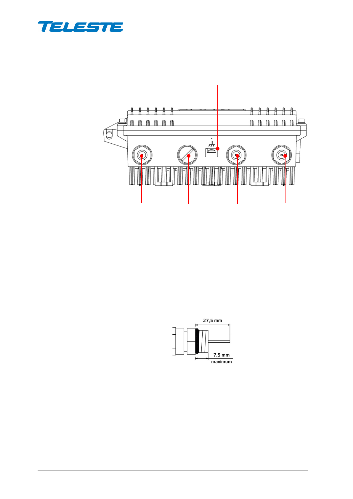
Interfaces
8616013
Figure 2. Port locations – bottom view
The AC1500 amplifier has four dedicated cable connection points: input, input
bypass/output and two outputs. The amount and function of the actual
connectors varies with the chosen configuration.
All RF ports have a standard PG11 thread and they accept any KDC type
adapter or connector. Suitable length for the centre conductor pin is
approximately 20 mm (Figure 3). Screw the KDC connector/adapter body into
the port. Tighten the centre conductor seizure screw and torque to 0.7 Nm. Do
not over tighten.
8604025
Figure 3. Centre conductor length
Grounding point
Input port
Output port 1
Output port 2
Input bypass / Output port 3

User manual AC1500
59300547 Rev.001
21.4.2016 5(16)
Powering
NOTE! To reduce the risk of electric shock, do not remove the
shielding cover of the power supply unit if it is connected. All
electrical installations must be carried out by authorized and
competent technicians in accordance with the national or regional
electrical regulations.
Common precautions:
•The AC1500 amplifier is intended for installation in restricted access
locations (dedicated equipment rooms, equipment closet, or the like)
•Operate the device only on the specified supply voltage.
•The AC1500 must never be operated without its power supply unit
shielding cover.
•The AC1500 has no separate power switch thus the power plug must
be easily accessible.
•Disconnect the power cord by the connector only. Never pull on the
cable portion of the power cord.
•Do not place or drop heavy or sharp-edged objects on the power cord.
•The power must be disconnected when installing or removing the
AC1500.
The AC1500 can be powered by several PSU options. Every option has its own
advantages and limitations which are described briefly as follows.
230 V AC:
The locally powered AC1500 amplifier is connected to the mains voltage of
205…255 V AC via its own power cord. The power supply unit (AC6313) is
double shielded and does not require separate grounding. However, ensure that
the housing of the AC1500 is properly connected to the earth in order to meet
safety requirements. Proper grounding will also improve protection from the
effects of interference and thus increase the overall reliability of the system.
27...65 V AC:
The ACE6314 power supply unit accepts 27...65 V AC either via a coaxial cable
by inserting a fuse to the corresponding fuse holder or directly at the external
input. The external input is located on the power distribution board at the upper
right corner of the node. External power can also be fed through the node into
the network. Maximum feed-through current is 7 A per port (15 A total). If
powering will be provided through a dedicated output port, the port must be
equipped with a fuse (supplied).
40...90 V AC:
The node can alternatively be delivered with a 40...90 VAC (square or quasi
square) for remote supply. Power is supplied either via a coaxial cable by
inserting a fuse to the corresponding fuse holder or directly at the external input.
The external input is located on the power distribution board at the upper right
corner of the node. External power can also be fed through the node into the
network. Maximum feed-through current is 7 A per port (15 A total). If powering
will be provided through a dedicated output port, the port must be equipped with
a fuse (supplied). Note! This PSU option (AC6315) is not fully compliant with the
EN 60728-11:2010 standard because powering voltage can exceed 65 V AC.
User manual AC1500
59300547 Rev.001
21.4.2016 6(16)
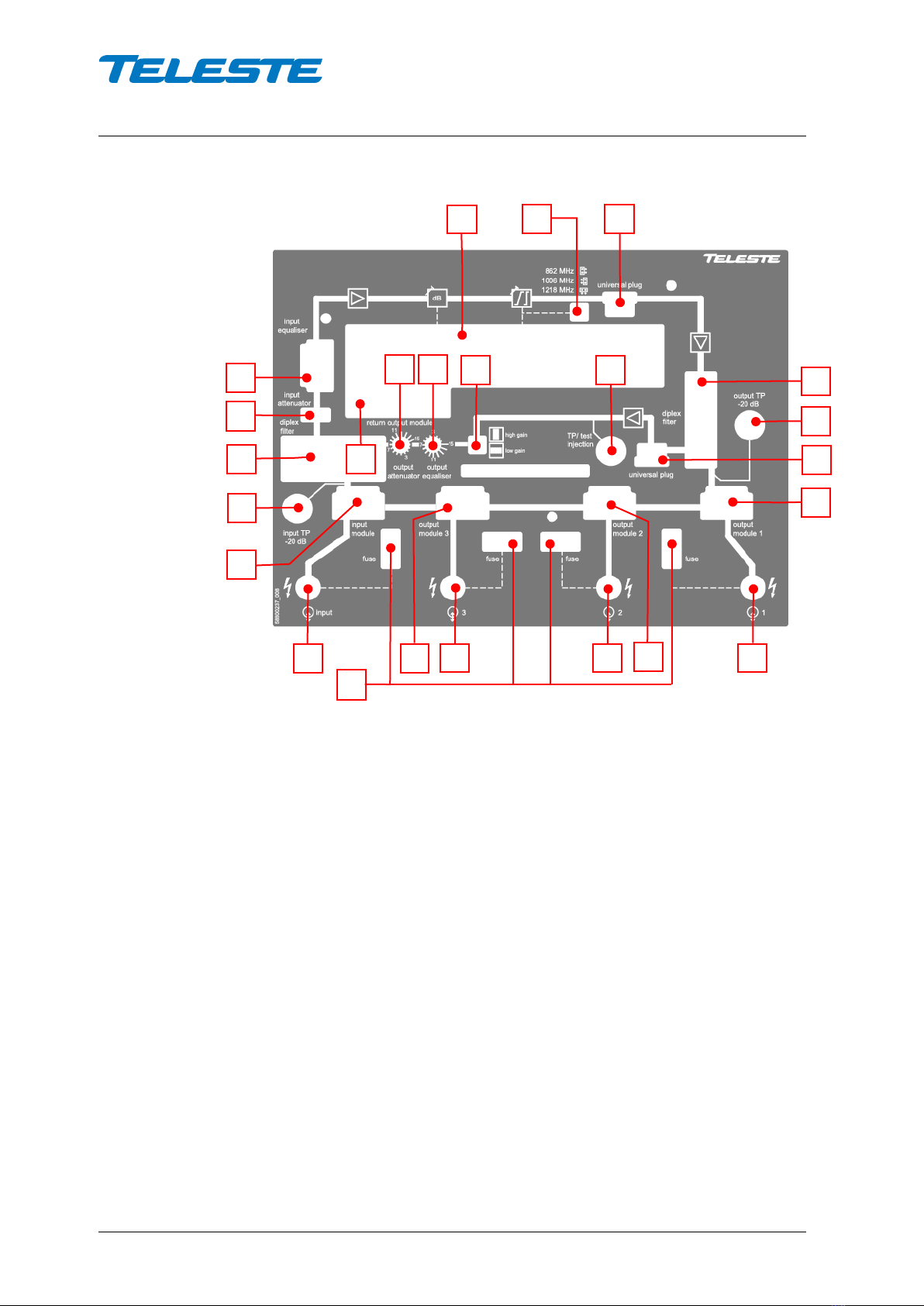
Front panel
8615015
Figure 4. AC1500 front panel
1) Input centre conductor seizure screw
2) Input module (see table 1)
3) Input test point
4) Input diplex filter
5) Attenuator for downstream RF signal
6) Equaliser for downstream RF signal
7) Slot for ALSC / MLSC / transponder
8) Interstage slope pivot point selection
9) Downstream universal plug-in
10) Output diplex filter
11) Output test point
12) Upstream universal plug-in
13) Output module 1 (see table 2)
14) Output 1 centre conductor seizure screw
15) Output module 2 (see table 3)
16) Output 2 centre conductor seizure screw
17) Output 3 centre conductor seizure screw
18) Output module 3
19) Fuse(s)
20) Return output module
21) Attenuator for upstream RF signal
22) Equaliser for upstream RF signal
23) Upstream gain mode selection
24) Upstream test point / injection point
19
1
2
3
4
5
15
14
12
16
17
23
24
6
22
21
20
13
7
8
9
11
18
10
User manual AC1500
59300547 Rev.001
21.4.2016 7(16)
Features
Diplex, input and output modules, return path module
The AC1500 amplifier is delivered according to the specifications defined in the
ordering code.
Optional return path operation needs plug-in diplex filters
(Figure 4, positions 4 and 10). The available diplex filter types are CXF065
(65/85 MHz), CXF085 (85/105 MHz) and CXF204 (204/258 MHz). It is also
possible to order the amplifier without diplex filters.
Input and output modules are passive plug-ins used to control the outputs – see
tables 1,2and 3. During amplifier adjustment the plug-in unit positions for input
and output modules must be equipped at least with the 0 dB modules.
Module
Functionality as input module
Input
Bypass
AC6110
0 dB input module, no bypass
0 dB
not used
AC6124
Two-way splitter, bypass in use
-4 dB
-7 dB *)
AC6113 2/12 dB tap, bypass in use -12 dB -5 dB *)
AC6115
1/16 dB tap, bypass in use
-16 dB
-4 dB *)
Table 1. Input modules with corresponding nominal attenuation values
*) Bypass attenuation includes fixed 3 dB insertion loss of the internal bypass circuit.
Module
Output module 1
Output 1
Output 2
AC6120
0 dB output module,
0 dB
not used
AC6124 Two-way splitter -4 dB -4 dB
AC6113
2/12 dB tap
-2 dB
-12 dB
AC6115
1/16 dB tap
-1 dB
-16 dB
Table 2. Output modules with corresponding nominal attenuation values
Module
Output module 2
Output 2
Output 3
AC6120 0 dB output module 0 dB
not used
or bypass
AC6124
Two-way splitter
-4 dB
-4 dB
AC6113
2/12 dB tap
-2 dB
-12 dB
AC6115
1/16 dB tap
-1 dB
-16 dB
Table 3. Output modules with corresponding nominal attenuation values
Output module 2 usage is similar to Output module 1.
Installed output module 2 controls how amplifier bypass / output 3 port is
configured. When output module 2 slot is equipped with AC6120 module, this
port is input bypass port. When output module 2 slot is equipped with a tap or
splitter module, this port is output 3 port.
AC1500 has return amplifier built in on the motherboard. For upgrading return
path there is no need to change return amplifier, but only diplex filters and the

User manual AC1500
59300547 Rev.001
21.4.2016 8(16)
passive return path module. Options for the return path module (Figure 4
pos. 20) are AC6250 (65 MHz), AC6251 (85 MHz) and AC6252 (204 MHz).
Setup
Preparation
Check installed plug-in modules in the amplifier. Note! Amplifier does not work if
one of these components is missing.
−Install input and output diplex filters as called for by design.
−Install input attenuator and input equalizer as called for by design.
−Select appropriate interstage pivot point according system’s highest
frequency.
−Install ALSC, MLSC or transponder unit. Assuming AC6158 or AC6188 is
in use adjust the gain and slope controls to mid-position (Gain: 0 dB,
Slope: 0 dB).
−Select appropriate plug-in module into forward path universal plug-in slot
to set the operative gain according to amplifier usage (Trunk/distribution).
−Return path universal plug-in slot must be equipped at least with the 0 dB
JDA series attenuator.
−Check the presence of return path gain mode selector. Start with “low
gain”, use “high gain” mode only if needed.
−Install return path module with designed frequency range.
Forward path
Verify adequate signal at the input of the amplifier (Figure 4. pos. 3) Note! If the
income level of the amplifier is quite high or unknown, replace the input
attenuator with an attenuator of rather big attenuation value e.g. JDA915 (15
dB).
Set the output slope of the amplifier according to the network plan calculation by
means of input equaliser (Figure 4 pos. 6). The signal can be measured at the
-20 dB output test point (Figure 4 pos. 11). To reach the desired output level
select an appropriate input attenuator for the plug-in position 5 (Figure 4). Both
attenuation and slope control is achieved by plug-ins of the JDA series type
ranging from 0 dB to 20 dB in 1 dB steps. Output level and slope can be fine-
tuned with AC6158/AC6188.
Assuming that AC6158 ALSC module is in use, switch it to “ALSC On” mode.
ALSC (Automatic Level and Slope Control) keeps the output signal level stable
irrespective of input signal level variations by adjusting the interstage gain and
slope controls based on the pilots. Gain and slope are adjusted slowly in small
steps to guarantee stable operation in long amplifier cascades.
If new output levels need to be set, ALSC should be first disabled, then gain
and slope adjusted (with manual controls or plug-in modules) to achieve desired
pilot levels, and then ALSC enabled again.
Return path
The return path adjustment is based on unity gain principle such that the return
path gain of the amplifier station exactly matches the loss of the cable following
it (i.e. the cable span toward the headend).

User manual AC1500
59300547 Rev.001
21.4.2016 9(16)
The return path requires a specific signal level for proper operation. The ideal
level at the amplifier is based on the incoming power and the maximum loss
through which that signal must travel on its way to the amplifier. A typical
individual channel level at the return path input is in range of
•70…80 dBµV with 65 MHz US
•65…70 dBµV with 204 MHz US
Inject a signal of known power into the test signal injection point (Figure 4 pos.
24) and measure the output level at the headend. Once the signal is received at
the headend, it can be measured and the information sent into the forward path
as a narrowband signal. This signal can be detected from the -20 dB test point
(Figure 4 pos. 11). Adjust the gain (Figure 4 pos. 21) and slope (Figure 4 pos.
22) of the amplifier until the target level is produced. Maximum control range for
the return path slope is 15 dB. The upstream level adjustment range is 15 dB.
Options for level and slope control
AC1500 can be equipped with different control modules, offering different level
of automation and remote management.
AC6158 / AC6188 control modules
AC6158 is an ALSC module for automatic gain and slope adjustment. It
measures two user adjustable pilot signals and adjusts the amplifier interstage
gain and slope controls to maintain constant amplifier output level.
AC6188 does not support pilot detection or ALSC, otherwise the two modules
are identical. Thus all references to AC6158 in this manual are valid also for
AC6188 unless otherwise stated.
Both modules support manual gain and slope control and return path ingress
switch control via local UI. They also support Remote Ingress Switching (RIS)
which allows remote ingress switch control via forward path data link using
HDM155 RIS controller module.
AC6952 transponder
AC6952 is an element management transponder with forward and return path
level measurement and ALSC controller unit. AC6952 can be plugged into the
amplifier's transponder slot. Note! AC6952 is applicable with 65 MHz or 85 MHz
upstream signal path.
AC6952 transponder software supports both CATVisor and HMS remote
communication protocols. The communication protocol can be changed via the
user interface.
User manual AC1500
59300547 Rev.001
21.4.2016 10(16)
Installation
To install an AC6158 unit, first locate the correct installation position in AC1500
or AC2500 amplifier. Snap off the segments of the shrouds break-away type
slot cover and remove the slot cover. Insert the unit by pressing it gently into
place. The unit will fit only in one orientation.
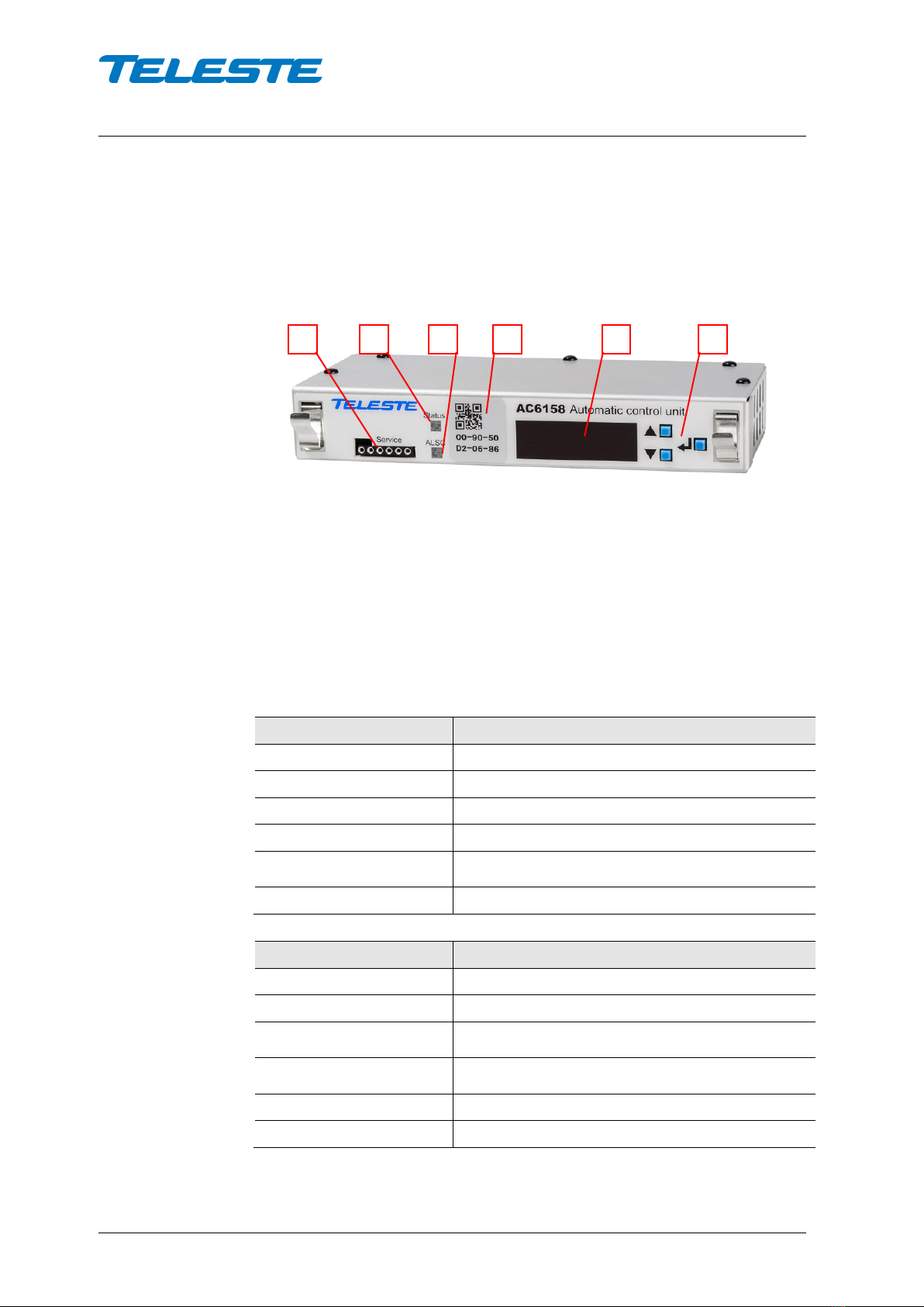
Front panel
Figure 5. AC6158 front panel, 1) Service port (factory use only), 2) Indicator for module
and RIS status, 3) Indicator for ALSC status (AC6158 only), 4) MAC address, 5) Led
display, 6) Up / Down / Enter buttons
Indicators
The two led indicators on the front panel are labelled as "Status" and "ALSC" (in
AC6158 only). During the power-up sequence both leds will be yellow and
"Teleste" text scrolls through the display.
Status led Description
██████████ green Operation OK, locked to RIS carrier
██████████ green blink Operation OK, received RIS packet
██████████ yellow Operation OK, RIS carrier not found
██████████ red Platform not recognised ("PLAT" in display)
██████████ red blink
Internal error ("ERR" in display). If reinsertion
doesn't help, unit should be sent to service
██████████ dark Software / power failure
ALSC led (AC6158 only) Description
██████████ green Pilots OK, gain & slope OK, pilot targets achieved
██████████ green blink Pilots OK, adjusting gain and/or slope
██████████ yellow
One pilot lost or gain saturated or slope saturated.
See UI's "ALSC" item for more details.
██████████ yellow blink
One pilot lost or gain saturated or slope saturated,
adjusting gain and/or slope
██████████ red Both pilots lost, adjustments frozen
██████████ dark ALSC disabled
1
2
3
4
5
6

User manual AC1500
59300547 Rev.001
21.4.2016 11(16)
User interface
During the power-up sequence "Teleste" text scrolls through AC6158 display. If
there is no button activity during ~3 minutes, the display will go dark. Pressing
any button wakes up the display and activates the first menu item.
The menu structure is described below. The Up / Down buttons browse through
the menu items, Enter button selects the item for modification / reading, Up /
Down changes the value of a parameter and Enter returns to the menu.
ONLY IN AC6158
ONLY WITH AC2500
ALSC: Off or On / High pilot
lost / Low pilot lost / Gain
saturated / Slope saturated
High pilot frequency
[MHz]
High pilot type
[Analog / Digital]
Low pilot frequency
[MHz]
Low pilot type
[Analog / Digital]
Gain
[dB]
Slope
[dB]
Cable type [Ground / Short
aerial / Long aerial]
Ingress switch 1 control
[0 dB / -6 dB / -50 dB]
Ingress switch 2 control
[0 dB / -6 dB / -50 dB]
RIS communication status
[Scanning / locked to MHz]
Software version
MAC address
Reset to factory settings
Enter button
UP / DOWN buttons
Perform factory reset
ALSC menu shows "On" or "Off" when everything is OK, otherwise an error
message is displayed instead: ERR.H = high pilot missing, ERR.L = low pilot
missing, ERR.G = gain saturated, ERR.S = slope saturated.
If there is an internal error or amplifier type cannot be detected, "ERR" is
displayed and the UI cannot be used.
If amplifier type is not supported, "PLAT" is displyed and the UI cannot be used.
Pilot frequency can be edited in 0.25 MHz steps, although the last digit is not
visible in the UI.

User manual AC1500
59300547 Rev.001
21.4.2016 12(16)
Manual gain and slope control
AC1500 and AC2500 amplifiers' electrical interstage gain and slope controls
can be manually adjusted in -5…+5 dB range with 0.5 dB steps. The values are
stored in the amplifier memory, default is 0 dB. Note that adjustment values
above ±4 dB may not be always achieved, depending on unit, temperature and
selected cabling type.
The gain and slope controls can be manually adjusted also when ALSC is
enabled, but ALSC continues adjusting and thus usually cancels the manual
adjustment. If new output levels need to be set, ALSC should be first disabled,
then gain and slope adjusted (with manual controls or plug-in modules) to
achieve desired pilot levels, and then ALSC enabled again.
The selected cabling type affects gain and slope temperature compensation.
With "Ground" cabling type, only amplifier's own temperature-induced variation
is compensated. "Short air cable" and "Long air cable" compensate for typical
250 m and 400 m aerial cables, respectively, in addition to the amplifier's own
variation. The cabling type selection makes it possible to use fewer ALSC units
in an amplifier cascade than is possible with traditional circuitry that
compensates only for amplifier's own variation. The cabling type is stored in
amplifier memory, default is "Ground". Note that cable type selection also
affects ALSC operation if pilot(s) are missing.
Automatic gain and slope control (AC6158 only)
ALSC uses two pilots to keep amplifier output levels stable. Normally the high
pilot controls amplifier gain and the low pilot controls slope. When there is more
than 0.5 dB difference between target and measured pilot levels, ALSC starts
adjusting (ALSC led blinking green) and adjusts until pilot level error is below
0.3 dB (ALSC led solid green) or gain/slope saturates (ALSC led yellow, and
blinks if adjusting continues). ALSC adjusts gain and slope slowly in small
increments to prevent oscillation in long amplifier cascades.
If either pilot is lost, i.e. its level falls below ~75…80 dBµV, slope control is
frozen and gain is controlled with the remaining pilot (ALSC led yellow). If both
pilots are lost, gain and slope controls are both frozen (ALSC led red).
The pilot frequencies in 0.25 MHz steps and pilot types ("Analog" for peak
detection, "Digital" for average detection) are stored in amplifier memory. They
should be set correctly before enabling ALSC. These settings are read-only
when ALSC is enabled.
The target pilot levels are memorised by AC6158 every time ALSC is enabled,
and stored in AC6158 memory. ALSC cannot be enabled if pilots are missing.
If ALSC is enabled with gain or slope values other than 0 dB, the adjustment
range is reduced. Thus the recommended adjustment method is to first disable
ALSC and set gain and slope to 0 dB. Output can then be adjusted to desired
value by inserting appropriate input plug-in modules. If fine-tuning is needed, it
can be done via UI gain and slope controls before finally enabling ALSC.
Local ingress switch control
The amplifier ingress switch(es) can be controlled via local UI. The setting is
stored in amplifier memory, default is 0 dB. If ingress switch commands are
received via RIS, they override local commands.
User manual AC1500
59300547 Rev.001
21.4.2016 13(16)
Remote ingress switching
Teleste RIS (Remote Ingress Switching) system allows low cost ingress
detection and countermeasures at headend. It consists of a head-end HDM155
RIS controller module which communicates with RIS receiver modules such as
AC6158 installed in the field equipment using one-way forward path RF link.
RIS communication addressing is based on the AC6158 MAC address. The
MAC address is visible in the front panel sticker in both human readable (only
last 3 bytes, start is always 009050) and 2-D barcode format, and can also be
checked via the UI.
AC6158 RIS receiver scans for RIS carrier within its tuning range, starting from
the previously found carrier frequency. Scanning is indicated with yellow Status
led. When a carrier is found and packet sync is established, Status led goes
green and AC6158 acts according to the received commands. If the carrier is
lost for >1 minute, scanning is resumed.
Received RIS packet is indicated with short dark blink on Status led.
Refer to HDM155 RIS controller documentation for more details on the RIS
system and commands.
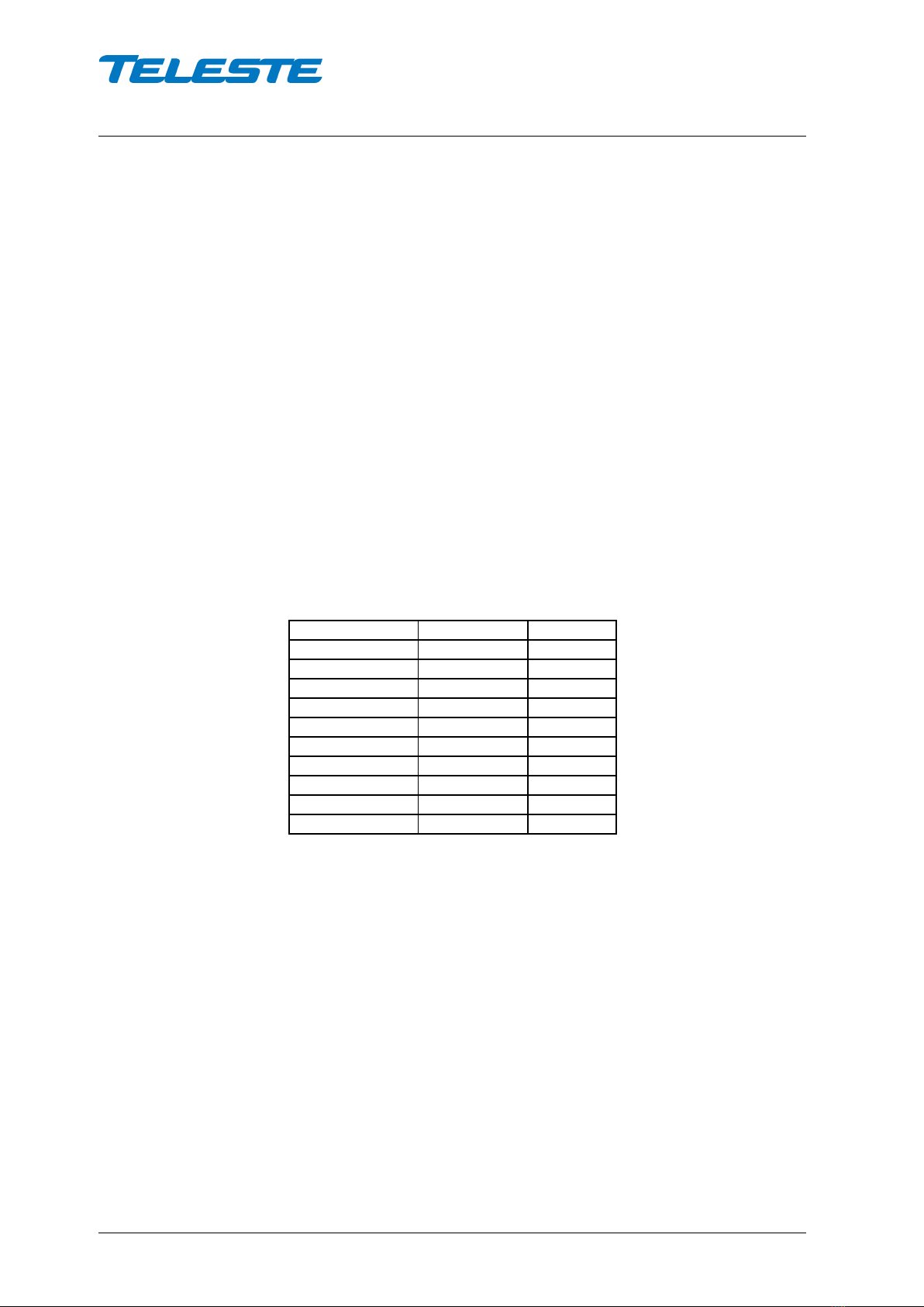
Factory default settings
When "Reset to factory settings" is selected on the UI, the following values are
stored and taken into use:
Parameter
Stored into
Default
ALSC status
AC61x8
Off
High pilot freq
motherboard
858 MHz
High pilot type
motherboard
Digital
Low pilot freq
motherboard
290 MHz
Low pilot type
motherboard
Digital
Gain
motherboard
0 dB
Slope
motherboard
0 dB
Cable type
motherboard
Ground
Ingress1
motherboard
0 dB
Ingress2
motherboard
0 dB
User manual AC1500
59300547 Rev.001
21.4.2016 14(16)
Legal declarations
Copyright © 2016 Teleste Corporation. All rights reserved.
TELESTE is a registered trademark of Teleste Corporation. Other product and
service marks are property of their respective owners.
This document is protected by copyright laws. Unauthorized distribution or
reproduction of this document is strictly prohibited.
Teleste reserves the right to make changes to any of the products described in
this document without notice and all specifications are subject to change without
notice. Current product specifications are stated in the latest versions of
detailed product specifications.
To the maximum extent permitted by applicable law, under no circumstances
shall Teleste be responsible for any loss of data or income or any special,
incidental, consequential or indirect damages howsoever caused.
The contents of this document are provided "as is". Except as required by
applicable law, no warranties of any kind, either express or implied, including,
but not limited to, the implied warranties of merchantability and fitness for a
particular purpose, are made in relation to the accuracy, reliability or contents of
this document.
Teleste reserves the right to revise this document or withdraw it at any time
without notice.
Teleste Corporation
P.O. Box 323
FI-20101 Turku
Street address: Telestenkatu 1, 20660 Littoinen
FINLAND
www.teleste.com

Notes

This manual suits for next models
2
Table of contents
Other Teleste Amplifier manuals


