Teleste AC1000 User manual

User Manual AC1000
59300001 Rev.003
Broadband Cable Networks December 17, 2002 1(11)
printed on December 17, 2002
A: AC1000 AMPLIFIER PLATFORM
General
The AC1000 is a single active output amplifier with
high gain. The amplifier can be used for distribution
purpose at high gain mode and also as a line
amplifier with lower gain. It is extremely versatile
and scalable through a wide range of plug-in
options. The amplifier platform can also be easily
upgraded to operate as a fibre node. The part A of
this document is devoted to procedures possible
while the Access platform is used as an amplifier.
Similar information concerning the fibre node will be
found in part B of this document respectively.
Installation
TheAC1000canbeinstalledeitherintoastreet
cabinet or to an outdoor environment. The node
should be installed in a vertical position so that the
external cable connectors are underneath. Secure
the housing with three mounting brackets – see
fig.1 for the positions of mounting brackets as well
as other installation dimensions.
The cover opens with the hinges to the left. The
open cover can be removed by first opening the
cover into a 90 degrees angle and the lifting it off
the hinges. Close the lid by tightening the four
retaining bolts in a diagonal sequence. Before
closing the lid check that
-nothing is trapped between the lid and the case
- all case gaskets are in their correct positions
A sufficient tightening torque is 3 Nm. Ensure that
the lid seats evenly on the rubber gasket. The class
of enclosure is IP54.
To ground the amplifier housing connect at least
4mm
2grounding wire (Cu) from a proper earth to
the grounding point (see the arrow in fig.1).
Cable connections
Underneath the AC1000 amplifier there are four
cable connection points: input, input bypass/output
and two outputs. The amount and function of the
actual connectors varies with the chosen
configuration. All coaxial outputs have a standard
PG11 thread and they accept any KDC type
adapter or connector. A suitable length of the cable
inner conductor exposed for the connectors is
approximately 20 mm (fig.2).
8602013
Fig.1. Dimensions of the AC1000
housing and the grounding point
location
Type Description
AC6110 0 dB input module
AC6112 1/12 dB tap
AC6120 0 dB output module
AC6124 two-way splitter
AC6128 2/9 dB tap
AC6111 termination module
Table 1. List of available input and
output connector modules
ac1000_rf
Fig.2. RF cable connector
User Manual AC1000
59300001 Rev.003
Broadband Cable Networks December 17, 2002 2(11)
printed on December 17, 2002
Power feed
The supply voltage of the remote powered amplifier (27...65 V AC or ± 33...90 V
DC) can be fed through any of the cable connections by inserting a fuse to the
corresponding fuseholder (fig.3 pos.22). When a cable connection is used for
powering, the maximum supply current is 8.0 A.
The power intake of the remote powered amplifier may also be done externally
via the cable feed-through that is located on the upper left corner of the
amplifier. In this case the maximum supply current is 12.0 A.
External power can also be fed through the amplifier into the network. Maximum
feed-through current is 8.0 A per port.
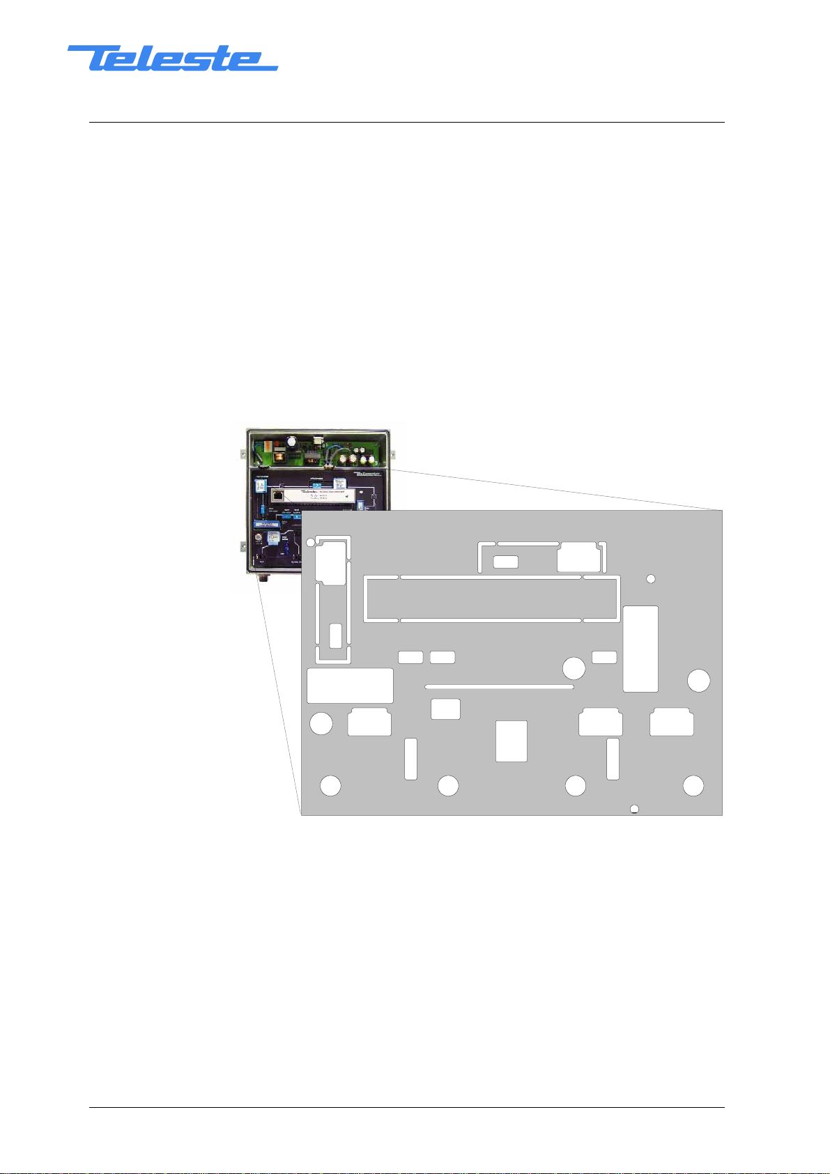
Connectors and plug-in unit slots
Fig.3. AC1000 plug-in placement,
1) Input
2) Input by-pass / Output 3 (*)
3) Output 2
4) Output 1
5) Input test point, -20 dB transformer
6) Test signal injection point, -30 dB
transformer
7) Output test point, -20 dB directional
coupler
8) Input module (see table 1)
9) Input diplex filter
10) Input attenuator
11) Input equaliser
12) Slot for element management
transponder module
13) Interstage attenuator
14) Interstage equaliser
15) Output diplex filter
16) Return path input attenuator
17) Return path equaliser
18) Return path attenuator
19) Output module 1 (see table 1)
20) Output module 2 (see table 1)
21) Input by-pass / Output 3 jumper (*)
22) Fuse(s)
*) See chapter Jumper settings (next page)
1234
5
67
8
9
10
12
13
15
16
17
18
19
20
21
22
22
22
11 14

User Manual AC1000
59300001 Rev.003
Broadband Cable Networks December 17, 2002 3(11)
printed on December 17, 2002
Adjustments
Forward path
The AC1000 is available in many configurations to fill various network
requirements. The amplifier is delivered according to the specifications defined
in the ordering code. Optional return path operation needs plug-in diplex filters.
The available diplex filter types are CXF030 (30/47 MHz), CXF042 (42/54 MHz),
CXF050 (50/70 MHz) and CXF065 (65/85 MHz). It is also possible to order the
amplifier with no diplexers, in which case the diplex filters are replaced by
forward path jumpers CXF000. In addition an optional element management
transponder module is available allowing remote monitoring and controlling of
the amplifier.
The input and output amplifier stages are both based on high performance
solutions which allows the operator to set this amplifier’s outputs for trunk or
distribution levels. Input and output modules are passive plug-ins used to
control the outputs – see table 1. During the adjustment the plug-in unit
positions for input and output modules must be equipped at least with the 0 dB
modules.
Install the interstage equaliser and attenuator plug-ins (fig.3 pos.14 and 13)
according the network plan. The network plan should specify exact signal
values.
Set the output slope of the amplifier according to the network plan calculation by
means of input equaliser (fig.3 pos.11). The signal can be measured at the
-20 dB output test point (fig.3 pos.7). To reach finally the desired output level
select an appropriate input attenuator for the plug-in position 10 (fig.3). Note! If
the income level of the amplifier is quite high or unknown, replace the input
attenuator in position 10 (fig.3) with an attenuator of rather big attenuation value
e.g. JDA915 (15 dB, 860 MHz).
Return path
The return path adjustment is based on unity gain principle such that the return
path gain of the amplifier station exactly matches the loss of the cable following
it (i.e., the cable span toward the headend). Inject a signal of known power into
the test signal injection point (fig.3 pos.6) in the amplifier and measure the
output level in the headend. Once the signal is received at the headend, it can
be measured and the information sent into the forward path as a narrowband
signal. This signal can be detected from the -20 dB test point (fig.3 pos. 7).
Adjust the gain (fig.3 pos. 18) and slope (fig.3 pos.17) of the amplifier until the
target level is produced.
The return path requires a specific signal level for proper operation. The ideal
level at the amplifier is based on the incoming power and the maximum loss
through which that signal must travel on its way to the amplifier. A typical
individual channel level at the return path input is in range of 70…80 dBµV.
Usually the return path input attenuator (fig.3 pos.16) is set to 0 dB. If the
amplifier is used as the last amplifier in a network and it is followed with a
distribution network with an exceptional low attenuation, an extra attenuation
can be added. Attenuators of the JDA series type ranging from 0 dB to 20 dB in
1 dB steps are available.
If the return path is not in use, the return path attenuator (fig.3 pos.18) should
be removed. The termination towards the headend will then be completed
automatically. Alternatively the return path can be terminated towards

User Manual AC1000
59300001 Rev.003
Broadband Cable Networks December 17, 2002 4(11)
printed on December 17, 2002
fuse
by-pass / output 3
by-pass / output 3
client/network by replacing the return path input path attenuator (fig.3 pos.16)
with an attenuator of big attenuation value e.g. JDA920 (20dB, 860 MHz) or with
a 75 ohm termination plug-in JDA975.
Utilising remotely controlled ingress switch allows the operator to isolate
problems in return path and take corrective actions. The return path signal can
either be cut off (i.e. signal is attenuated more than 50 dB) or be attenuated by
6 dB. As default factory setting the ingress switch is set to 0 dB position. Since
homes may not always be connected to return path services, the return path RF
signal should be cut off by the management unit. Once connected, the ingress
switch should be set to 0 dB position.
Jumper settings
The function of the Input by-pass / Output 3 port (fig.3 pos.2) is selected with a
jumper (fig.3 pos.21). The jumper positions are displayed in the protective
covering inside the amplifier housing (see fig.4). When the jumper is in the by-
pass position, the input signal is passed straight through the amplifier into the
port in question. In case the jumper is in the output 3 position, the output signal
is fed into this port. Note! The output module 2 slot (fig.3 pos.20) has to be
fitted with a proper module (splitter or tap) to enable the third output port.
Fig.4. By-pass / Output 3 jumper location and settings

User Manual AC1000
59300001 Rev.003
Broadband Cable Networks December 17, 2002 5(11)
printed on December 17, 2002
B: AC1000 FIBRE NODE
General
The AC1000 is extremely versatile and scalable through a wide range of plug-in
options. The trend toward fibre deep architecture is also fully supported in the
Access amplifier platform. If smaller segments are needed due to increased
capacity demand the amplifier platform can be easily upgraded to operate as a
fibre node.
Information concerning installation, cable connections, powering and plug-in
placement can be found in part A of this document.
Fibre connections
The node can accept two fibre cables. These cables carries forward path and
return path optical signals. When feeding the optical cable in the node, a
suitable PG11 threaded feed-through adapter type KDO8xx, is available. NOTE!
Each KDO adapter is manufactured using a high quality precision and in order
to ensure the protection against water it is forbidden to mix up the parts of
different KDO adapters. The installation fibre filaments with connectors are fed
through the KDO type adapter. The fibre filament length inside the fibre
organiser is adjusted to sufficient measurement before tightening the adapter.
The adapter consists of two tightening nuts. Both nuts of the adapter are
tightened to the positive stop. The main nut against the mounting case is
tightened at first.
Fig.5. KDO832 adapter components
KDO832 is a fibre feedthrough adapter
for two 3 mm fibres.
Assemble the O-
ring 14x1.78, which
keeps the plastic halves together, to the
brass body.

User Manual AC1000
59300001 Rev.003
Broadband Cable Networks December 17, 2002 6(11)
printed on December 17, 2002
Fibre installation
Fibre installation is a critical procedure and it should be done with carefulness.
Incorrect handling of the fibre can result in damage and degraded performance.
Example of routing the fibres can be seen in figure 6.
When working with fibre pigtails and optical connectors, remember always:
-not to exceed the minimum bending radius
-to clean the fibre connectors before connecting them with ethyl or isopropanol
alcohol and dry it with pressurised air.
-to clean the connectors every time you disconnect them
Disconnected optical connectors may emit invisible optical radiation. Avoid
direct eye exposure to the beam. Laser light, visible or invisible, can seriously
injure eyes or even cause blindness
Fig.6. KDO832 The correct way to route the fibre pigtails.
Active modules
Optical receivers
The AC68x0’s are fibre optic receiver modules for the optical nodes of Access
platform. The performance and the features has been designed for the fibre to
the curb and the fibre to the building (FTTC/ FTTB) applications. Depending on
the optical input power, there are two kind of units available
AC6810 with an optical input power range ranging from -7 dBm to -2 dBm
AC6820 with an optical input power range ranging from -3 dBm to +2 dBm
Gain control
The optical receiver module is delivered without an attenuator plug. If necessary
use an attenuator plug-in to get appropriate RF level. Attenuators of the JDA900
series type ranging from 0 dB to 20 dB in 1 dB steps are available. The
attenuator value depends not only on the optical input level but also on the
optical receiver type and the OMI. Refer to the table below.

User Manual AC1000
59300001 Rev.003
Broadband Cable Networks December 17, 2002 7(11)
printed on December 17, 2002
Attenuator (4% OMI) Attenuator (5% OMI)
Opt. input level
(dBm) AC6810 AC6820 AC6810 AC6820
2 - JDA911 - JDA913
1 - JDA909 - JDA911
0 - JDA907 - JDA909
-1 - JDA905 - JDA907
-2 JDA911 JDA903 JDA913 JDA905
-3 JDA909 JDA901 JDA911 JDA903
-4 JDA907 - JDA909 -
-5 JDA905 - JDA907 -
-6 JDA903 - JDA905 -
-7 JDA901 - JDA903 -
Optical input power
The LED on the receivers front panel provides indication for the optical input
power.
LED on AC6810 Condition
Green Optical input power is within the nominal range
(-8.5…-1.0 dBm)
Yellow Optical input power drops below -8.5 dBm
Red Optical input power exceeds -1.0 dBm
LED on AC6820 Condition
Green Optical input power is within the nominal range
(-4.5…3.0 dBm)
Yellow Optical input power drops below -4.5 dBm
Red Optical input power exceeds 3.0 dBm

User Manual AC1000
59300001 Rev.003
Broadband Cable Networks December 17, 2002 8(11)
printed on December 17, 2002
Element management transponder
Some of the parameters can be controlled and monitored through the
transponder interface. The transponder unit will automatically detect the current
configuration of the Access platform when the user opens the Configuration
page. The Configuration page displays a graphical view of the current
configuration similar to the actual amplifier/node layout and also generates a set
of viewer pages individual to each active device. It is advisable to begin by
selecting the Configuration page at first since it is the only way to accomplish
the viewer pages. These pages include all the programmable controls and
settings.
Status
The type of the module as well as the measured optical input level is displayed
intheintheStatus frame. The background colour of the Optical level data field
changes to indicate alarms. A green background means legal values and red is
the symbol for an alarm.
Limits
The Limits frame displays the limits after which the unit starts indicating alarms.
The values are represented as read-only information. The manufacturer sets all
the limits.

User Manual AC1000
59300001 Rev.003
Broadband Cable Networks December 17, 2002 9(11)
printed on December 17, 2002
Optical return transmitters
There are a variety of options for transmitter modules available for the return
path applications of Access platform. The return path transmitters are available
either in 1310 nm Fabry-Perot, 1310 nm DFB or 1550 DFB versions. In addition
the platform can be equipped with CWDM transmitters. The CWDM lasers
deploy eight wavelengths in range of 1470 …1610 nm.
Gain control
The return transmitter module is delivered without an attenuator plug. If
necessary use an attenuator plug-in to give appropriate driving level for the
laser. Attenuators of the JDA900 series type ranging from 0 dB to 20 dB in 1 dB
steps are available.
In the front panel label (fig.7) is described the driving level at the test point that
gives 4 % OMI / channel. The input level should be adjusted to match this level
which is specified for each unit. For other OMI values, the needed plug
attenuator can be calculated from the formula:
20 xlog(new OMI% / 4%)
E.g. For 8 % OMI, a 6 dB higher input level is needed.
Depending on the nature of the return signal, the input level can be measured
as follows:
-When using a reference or test signal, the level of the carrier signal is
measured from the test point and it is adjusted to a value shown in the unit’s
label or calculated from it.
- When using a digital, noise like signal, the spectrum analyser’s noise marker
is adjusted to a same bandwidth as the digital signal has, and the level is
adjusted to a value shown in unit’s label or calculated from it.
Pilot
The pilot generator level corresponds to 4% OMI. Available pilot signal
frequency 4.5 MHz or 6.5 MHz can be controlled with a DIP switch on the
module’s front panel (fig.7).
ac3840ki
14
OFF
ON
Fig.7. AC6840 DIP switch positions

User Manual AC1000
59300001 Rev.003
Broadband Cable Networks December 17, 2002 10(11)
printed on December 17, 2002
Pin No. Setting Description
on Optical level: +2 dBm
1off Optical level: +1 dBm
on Pilot signal: 6.5 MHz
2off Pilot signal: 4.5 MHz
3 Not in use
4 Not in use
Table 2. Description of the DIP switch
Laser
Nominal optical powers are represented in table 2. The underlined functions are
default factory settings. With the DIP switch it is possible to reduce nominal
optical power by 1 dB. But OMI is also changed. However the product
specifications are valid only when using the nominal power.

User Manual AC1000
59300001 Rev.003
Broadband Cable Networks December 17, 2002 11(11)
printed on December 17, 2002
Element management transponder
Some of the parameters can be controlled and monitored through the
transponder interface. The transponder unit will automatically detect the current
configuration of the Access platform when the user opens the Configuration
page. The Configuration page displays a graphical view of the current
configuration similar to the actual amplifier/node layout and also generates a set
of viewer pages individual to each active device. It is advisable to begin by
selecting the Configuration page at first since it is the only way to accomplish
the viewer pages. These pages include all the programmable controls and
settings.
Status
The type of the module as well as the measured Laser current is displayed in
theintheStatus frame. The background colour of the Laser current data field
changes to indicate alarms and warnings. A green background means legal
values, red is the symbol for an alarm and yellow for a warning.
Limits
The Limits frame displays the limits after which the unit starts indicating either
alarms or warnings. The values are represented as read-only information. The
manufacturer sets all the limits.
Pilot
The pilot generator circuit can be controlled through the On/Off radio buttons.
Table of contents
Other Teleste Amplifier manuals


