Teletechnika Ltd. DHE-1000 Guide

DHE-1000
MPEG4 HD ENCODER
MPEG4 system with IP output
Technical documentation / Instruction set
Teletechnika Ltd.
3rd Edition / 6th November 2012

2
General description
The MPEG-2 compression that brought a revolutionary advance in the transmission of
picture and sound, by today was superseded by the MPEG-4 compression technique. On the
customers’ intensive demand Teletechnika developed the new generation of its encoders, the
MPEG-4 (H.264) Encoder. This version of the equipment allows the transmission of digital SDI
with embedded audio using H.264 MPEG-4 PART10 compression. Digitalized and compressed
voice and picture is composed to Single Program Transport Stream (SPTS). The output transport
stream includes the most important PSI/SI tables (PAT, PMT, SDT, NIT), thus in simpler systems
the encoder can be applied even without using a remultiplexer. This edition contains a 100 Base-T
Ethernet UDP/IP marked connector.
Structure
Features
•Digital video and audio input: SD/HD-SDI (with stereo embedded audio)
•Wide range of resolutions: 720x576i, 1280x720p, 1920x1080i
•System bitrate adjustable range of 1000 … 15000 kbps
•Audio bitrate adjustable between 32 and 384 kbps
•PSI inserter included with editable parameters
•Unicast / multicast UDP/IP output 100 Base-T full duplex mode ETH
•Separated management port for configuration
•Simple configuration in web browser
•Informative, wide display
•Low power consumption

3
Mechanical parameters, operation
The height of the encoder is 1 unit (1U) with 19’’ width and is supplied with standard
power cable.
In case of rack-mounted usage, the operator should take care of the proper airflow and
ventilation! Do not cover the case because it could cause overheating!
Hardware structure
Front Panel:
State indicator LEDs LCD
State indicator LEDs: Power OK
TS proper
Encoder setting, boot procedure
Serious internal problem
LCD:
2 line 40 character alphanumerical display, representing the state of the equipment on 12 pages:
1st page:
TS MAC Address: The MAC address of the UDP/IP marked ETH port.
TS IP:Port: The IP address of the UDP/IP marked port separated by a colon is the port.
2nd page:
Target IP:Port: The IP address of the destination side (DECODER) and the port on which
the decoder detects and filters.
Gateway IP: The IP Address of gateway if we use ‘Through gateway’ TS sending
(See below!)

4
3rd page:
Multicast MAC Address: The MAC Address of multicast sending in ‘To multicast’ mode in
hexadecimal format.
Streaming mode: Stopped: No TS output
Unicast to IP: TS sending in the local network without
gateway
Through Gateway: TS sending through a gateway if we use a
router to connection
To Multicast: TS sending to Multicast destination
4th page:
System bitrate: The set full TS bitrate in kilobits per second (=kbps).
Video bitrate: Comes from the system bitrate and audio bitrate. Also depends on
the PSI tables.
5th page:
Audio bitrate: The rate of the audio coding in kbps, possible values are:
32, 48, 56, 64, 80, 96, 112, 128, 160, 192, 224, 256, 320, 384
Audio Status: Indicates that there are embedded audio: Present or not: Muted
6th page:
The set PID values: PMT, VIDEO, AUDIO, PCR shown in hexadecimal format. The possible
values of PIDs are in 0x0020 … 0x1FFF range.
7th page:
Program ID: The Program identifier in hexadecimal format. The possible values
of this ID are in full 0x0000 … 0xFFFF range.
Program Provider: The name of program provider in maximum 20 characters.
8th page:
Program Name: The name of the program in max. 20 characters.
PSI Table Generator: Enabled / Disabled: The enabling of PSI tables. They contains:
PMT PID, Program ID, Program Provider, Program Name, Stream
ID, Network ID, Repetition Time, Network Name

5
9th page:
Stream ID: The identifier of the TS in hexadecimal format. The possible values
of this ID are in full 0x0000 … 0xFFFF range.
Repetition T: Repetition time of PSI table.
Network Name: The name of the network in max. 20 characters.
10th page:
MGMT IP: The IP address of the configuration port.
MASK: The network mask of the configuration port.
11th page:
MGMT Gateway: The Gateway IP address of the configuration port.
MGMT MAC address: The factory constant MAC address of the configuration port in
hexadecimal format.
12th page:
TRAP IP Address: SNMP trap destination IP address which to the equipment throws
the alarm traps. (In future feature)
TRAP server is: OFFLINE / ONLINE: The Encoder can ping the server or not.

6
Rear Panel:
230V AC: 230V power connector (cable included)
1AT: 1 Amper ’T’ type fuse, removable
POWER: Supply switch
MGMT: Management 10/100 Base-T Ethernet Port for configuration
PGM: Programmer connector just for service purposes.
UDP/IP: 100 Base-T Ethernet port for TS sending in UDP/IP packets.
SDI IN: Serial Digital Interface: Formerly the SDI interface was used only for linking
professional video equipment within the studio at the transmission of
uncompressed digital video signals. Today, the SDI interface can be found at
the inputs and outputs of more and more equipment of cable television and
other fields. Its great advantage is that one single coaxial cable can be used for
transmitting the picture and sound. The standard BNC connector on the back
panel of the MPEG-4 encoder is used for connecting the SDI signal. Over
time the SDI transmission developed to a fairly wide range of standard family.
The encoder supports the following formats: SD-SDI (SMPTE 259M, 270
Mbit / s), HD-SDI (SMPTE 292M, 1.485 Gbit / s). The transmission of sound
(embedded audio) is provided in the form of additional data, according to
SMPTE 272M (SD-SDI) and SMPTE 299M (HD-SDI).
Additional information: Due to the high bitrate use high-quality, double shielded coaxial cable, and try to minimize the length of
the cable, although originally the standard guarantees hundreds of meters of transmission quality.
230V AC POWER MGMT PGM UDP/IP SDI IN
1AT

7
User manual
The equipment could be started by turning the power switch ON, located beside power
connector. After the turn on, the POWER LED starts to light in case of faultless function. After
the start the LCD informs the user about the main state of the equipment:
At first by the boot procedure in the 1st line with the ‘Teletechnika Ltd. - MPEG4 HD
ENCODER’ label. In the 2nd line are the ‘Initializing .......’ label. Please wait by the boot section
about 15-20 seconds. By successful start an ‘OK’ word will appear after the points. If we have
some problem a ‘REBOOT!’ word and the equipment reboots until the successfully boot occurs.
Then, the previously described information displayed on the display.
Settings
The settings of the equipment only could be done via the MGMT connector. If there is
only a cable between the equipment end the computer it must be a crosslink type, otherwise e.g.
with a switch or router, the type of the used cable is not important.
To operate and reach the Encoder with our PC it has to be set into the same IP address
range as the equipment. The factory IP address of the equipment is on the 10th page of LCD. The
factory IP address begins with ‘192.168.1.’ with 255.255.255.0 mask.
8
Web surface
The general and IP settings of the equipment can be reached via our PC’s browser. Type
the IP address into the browser’s heading and press enter.
At first an username / password window will appear. In factory settings there are not
Username or Password. Please keep them clear and press Enter. After the first login every user
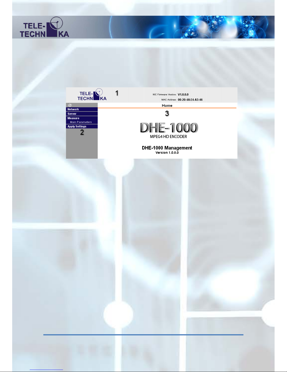
can change the Username and the Password. After logging in we can see the following web page:
Parts of the page
1. Header:
Teletechnika official webpage can be reached by clicking the Teletechnika logo at the left
corner.
In the line beginning with ‘NIC’ is the detailed version number of the used firmware.
After in the line beginning with ‘MAC’ we can see the equipment’s MAC address.
2. Menu bar (left):
House icon: Home page
Network: Network Settings
Server: Server Settings
Measure / Main parameters: Measured- and settable parameters of the equipment
Apply Settings: Save the Network and Server settings
3. Content page:
Page of the currently used menu point. Reset this push the Home icon and see the name
and version number of the currently used equipment.
9
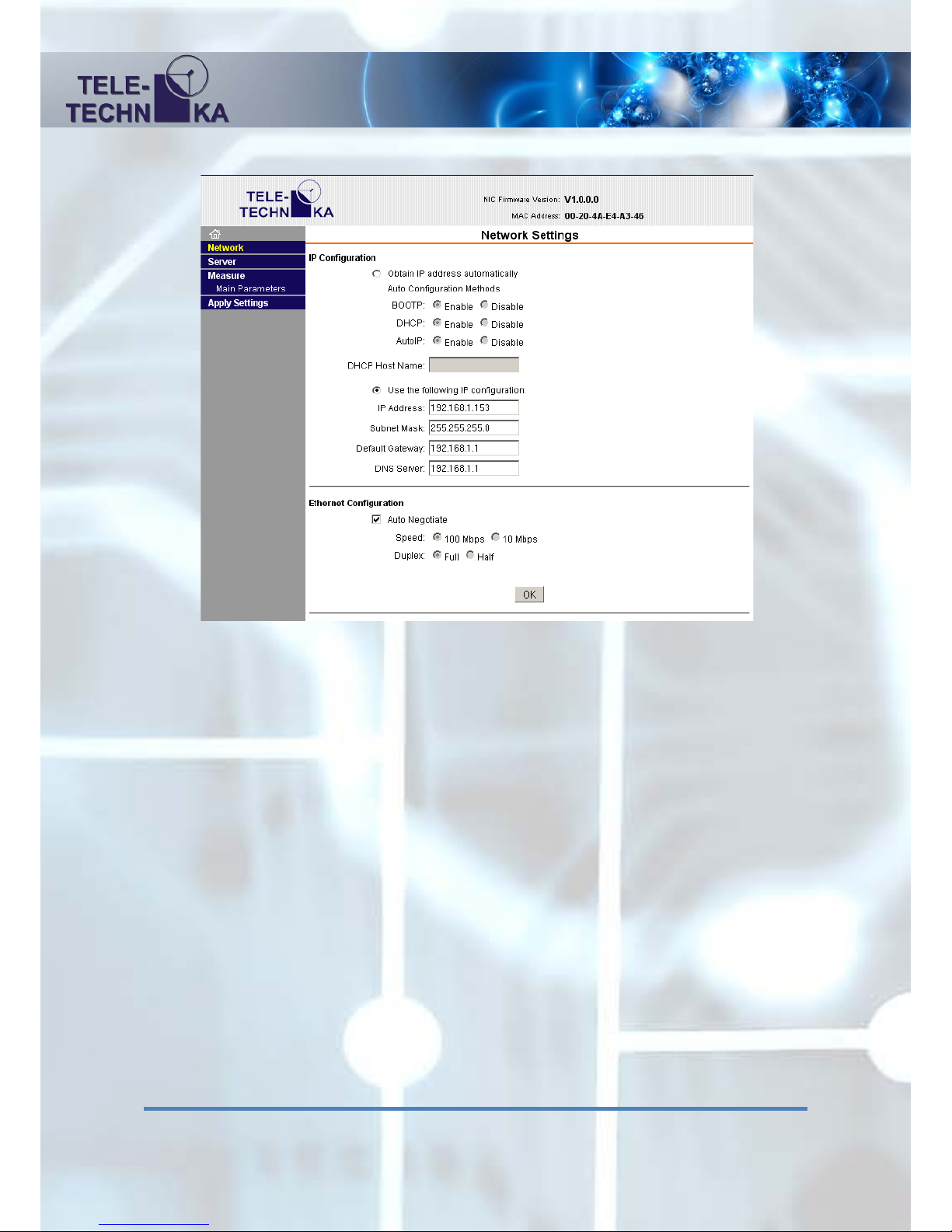
Network Settings
IP Configuration
Obtain IP address automatically:
DHCP: automatic IP settings from the used DHCP server
Use the following IP configuration:
Manual IP network settings:
IP Address: IP address of the equipment’s MGMT port
Subnet Mask: subnet mask of the equipment’s MGMT port
Default Gateway: default MGMT gateway
DNS Server: a DNS server’s address (not used)

10
Ethernet Configuration
(These settings should not be changed!)
Auto Negotiate: Check box for automatic negotiation
Speed: If Auto Negotiate is not checked give the parameters of the used network
10 or 100 Mbps
Duplex: Duplex- or half-duplex mode of the two way communication
OK: Prepare for sending the network settings
(if it is done it is marked with ‘DONE!’ line)
The option to apply settings in the Settings menu, you must click Apply.
Server Settings
Telnet/Web manager Password: Set the password for entering to the web surface
Retype Password: The password again for checking
We couldn’t give user name therefore by the login always keep it the user name field empty.
The password can be up to 4 digits. Note the password you specified, because without a password

11
reset operation is not possible without knowing the password.
Advanced
ARP Cache Timeout (secs): The timeout of the address resolution in seconds.
TCP Keepalive (secs): Alive hold time of the TCP connection in seconds.
Monitor Mode @ Bootup: Internal service mode enable / disable.
CPU Performance Mode: The internal CPU Performance mode, you should be high.
HTTP Server Port: The embedded web server port. Default: 80
MTU Size: Maximum packet size.
OK: On the Server Settings page Preparing to send (if the preparation has been 'Done!' Is
shown in the tab). The option to apply settings in the Settings menu, you must click Apply.
12
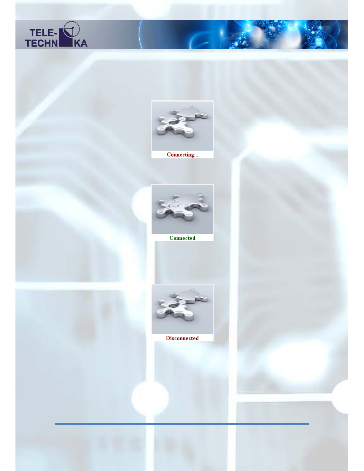
Measure / Main parameters:
Clicking this menu item in the web browser connects to the Encoder’s 10001 control TCP port.
The process of connecting a disconnected puzzle icon and the 'Connecting ...' label is marked:
If the connection is successfully a connected puzzle and a ’Connected’ label is displayed:
If you lose the connection with the device a disconnected puzzle again a ‘Disconnected’ label is
displayed:
If you have a physical relationship exists and still get Disconnected appears, make sure that only
one browser is opened and the device is not busy on the TCP socket port, as well as to get to the
10001 port on the device. If all the conditions are now in terms of the network device port access
control and still get disconnected inscription try to reconnect it click to another menu and then
come back. Make sure that Internet Explorer is used, do not open a browser and a few sheets of
the same Encoder device.
13
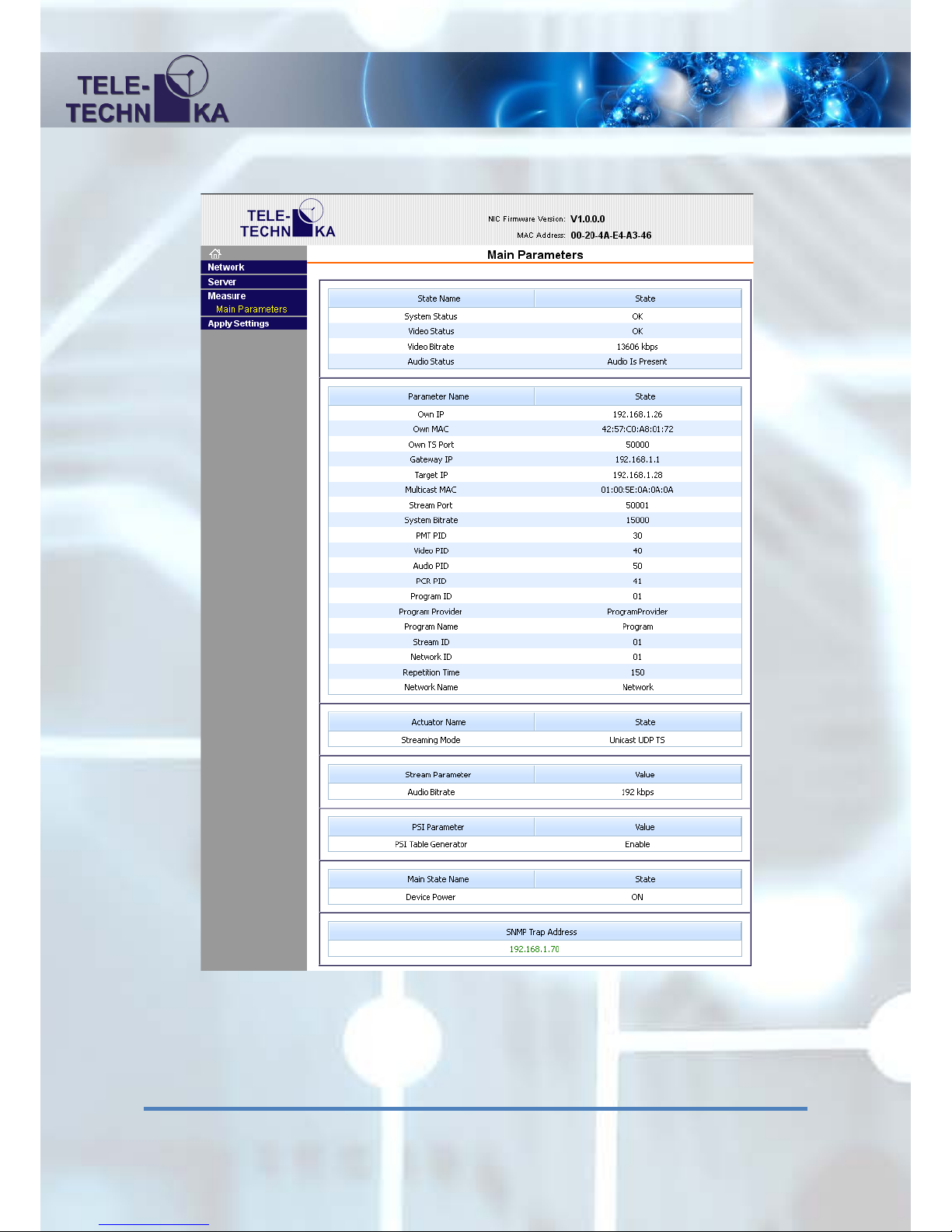
After a successful connection to the content page, and configured the device status parameters are
displayed:
The interface works: data query page when you open always happens, and it can be set to double
click on the desired field and press Enter, and rewrite the content fix it, you can return with
Escape. The measured information page is constantly updated each second.

14
Status field:
This section shows the measured parameters. The left side shows the name of the parameter. On
the right side is the parameter.
System Status: ‘OK’: Encoder module is works perfectly, ‘ERR’: Problem with the
encoder unit.
Video Status: ‘OK’: SDI video signal is connected, ‘Not Connected’: SDI video signal is
disconnected.
Video bitrate: The value of the video bitrate in kilobit per seconds. This value comes
from the system bitrate and audio bitrate. Also depends on the PSI tables.
Audio Status: Indicates that there are embedded audio: ‘Audio is Present’ or ‘No Audio’:
Muted
Settings field:
In this section can be set the parameters. The left side shows the name of the parameter. On the
right side can be change any parameter.
Own IP: The IP address of the UDP/IP marked port
Own MAC: The MAC address of the UDP/IP marked ETH port.
Own TS Port: The source TS Port.
Gateway IP: The IP Address of gateway if we use ‘Through gateway’
TS sending
Target IP: The IP address of the destination side (DECODER).
Multicast MAC: The MAC Address of multicast sending in ‘To multicast’
mode in hexadecimal format.
Stream Port: The destination port of TS.
System Bitrate: The full TS bitrate in kbps.
PMT, Video, Audio, PCR PID The PID values: PMT, VIDEO, AUDIO, PCR you can
specify in hexadecimal format. The possible values of PIDs
are in 0x0020 … 0x1FFF range.
Program ID: The Program identifier in hexadecimal format. The possible
values of this ID are in full 0x0000 … 0xFFFF range.
Program Provider: The name of the program provider in maximum 20
characters.
Program Name: The name of the program in max. 20 characters.
Stream ID: The identifier of the TS in hexadecimal format. The
possible values of this ID are in full 0x0000 … 0xFFFF
range.

15
Network ID: The identifier of the network in hexadecimal format. The possible
values of this ID are in full 0x0000 … 0xFFFF range.
Repetition Time: Repetition time of PSI table.
Network Name: The name of the network in max. 20 characters.
Streaming mode: Stopped: No TS output
Unicast UDP TS: TS sending in the local network without
gateway
Through Gateway: TS sending through a gateway if we use a
router to connection
Multicast UDP TS: TS sending to Multicast destination
Audio bitrate: The rate of the audio coding in kbps, possible values are:
32, 48, 56, 64, 80, 96, 112, 128, 160, 192, 224, 256, 320, 384
PSI Table Generator: Enabled / Disabled: The enabling of PSI tables. They contains:
PMT PID, Program ID, Program Provider, Program Name, Stream
ID, Network ID, Repetition Time, Network Name
Device Power: ON: Normal operation mode,
Reset: Do a reboot with the system.
SNMP Trap Address: The destination IP Address of the SNMP traps.
If the IP address is green it means that the 'Trap Server Online' as
the quick tip shows. If it is red then the first server does not see the
device ('Trap Server Offline').
Other Teletechnika Ltd. Media Converter manuals


