Interfacing to the KE-USB36 Input Header
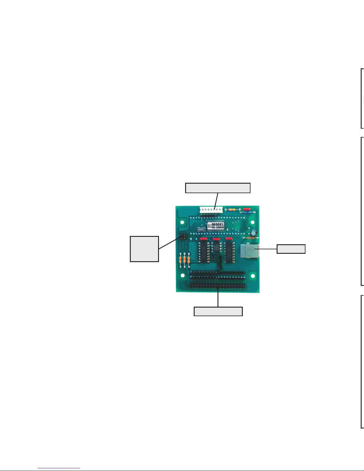
The KE-USB36 features a 2x20 header for interface to your input
devices. The input header is arranged with grounds on the end
pins of the header, and the 36 inputs between them. The board
is labeled near each header pin, designating the input number
that the pin represents. Each of the pins may be programmed to
emulate any key on a standard PC keyboard as well as the Left,
Middle, and Right mouse buttons.
Inputs on the KE-USB36 header are activated by shorting them
to one of the
provided logic
grounds on the
header. When
activated, the
input will report the keystroke that it has been programmed to
emulate. If held active, the keystroke will repeat (if programmed
to repeat), based on the repeat rates and delays set within the
operating system.
The inputs are intended to handle mechanical switch inputs and
are debounced for that purpose. Logic drivers may be attached
to the inputs as well, provided they are an active low, logic level
signal. Refer to the Appendix A on specifications for the timing of
logic signals. Never attach any external power to the Inputs.
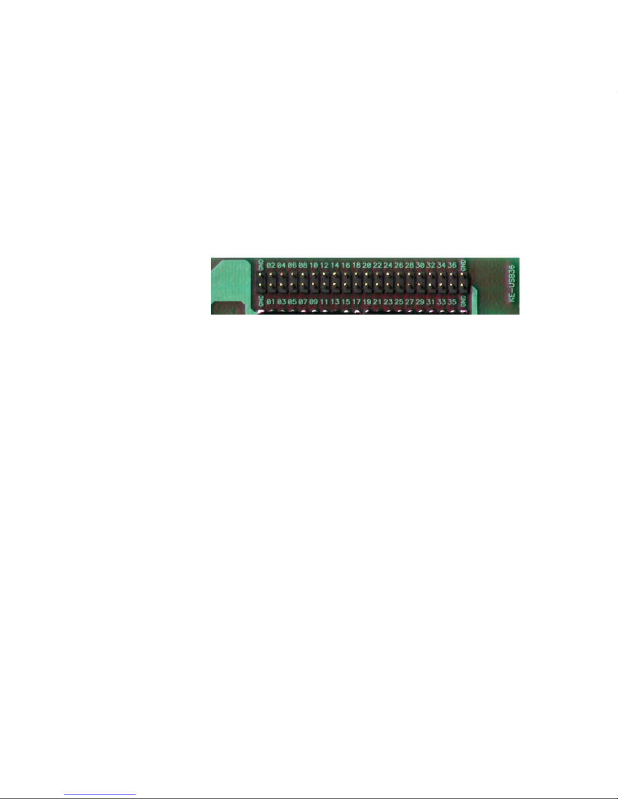
The KE-USB36 input header is a dual row header with .100”
spaced pins. This format is suitable for many readily available
connectors on the market, including a typical IDE hard drive cable.
Since all the inputs require the same logic ground reference, you
may “daisy chain” the ground to all of your switches. We also
offer a breakout board (our part number IOX36) for interface to
the KE-USB36. This interface board attaches to the KE-USB36
header through an IDE cable (provided with the IOX36). See
the accessories page of this manual for details on the IOX36.
Appendix B demonstrates connection techniques for switches on
Figure 4 - The KE-USB36 Input Header
a Trackball. Use the controls for either the X or Y axis for the
Spinner, according to the axis on which the Spinner movement is
to appear.
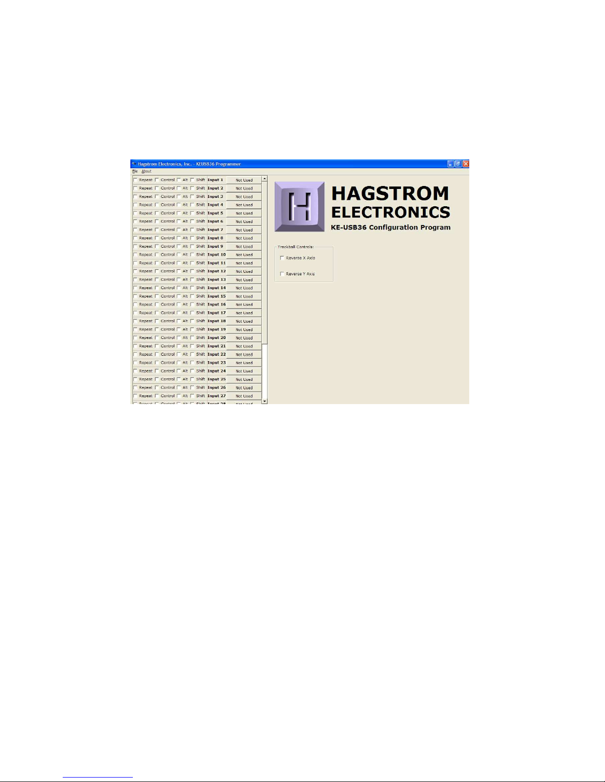
In order to accommodate the various brands of Trackballs, the
KE-USB36 provides check boxes to reverse the Left-Right and Up-
Down movements of the Trackball. If you find that one or both
directions of your cursor movement from the Trackball are reversed,
check the appropriate box in the configuration program.
The KE-USB36 uses the standard USB keyboard buffer length
which allows for up to six keys being reported “ON” at the same
time. This limitation only pertains to KE-USB36 inputs that are
programmed with the repeat selection enabled. Use of the Left and
Right Shift, Left and Right Alt, Left and Right Control, and Windows
GUI keys, can be used in addition to the six key limitation.
The KE-USB36 has the option of repeating an input that is held
on. If the input is selected to repeat, that input will count toward
the six key limit. Keys that are set to not produce a repeat will not
be subject to the 6 key limitation, provided there are no more
than 5 repeated keys currently active. Note that inputs defined as
mouse buttons do not figure into the six key limit.
Inputs on the KE-USB36 which emulate a multiple key sequence,
such as Shift+F1, will automatically have repeat disabled.
Appendix C:
KE-USB36 Read/Write from the Command Line
In addition to the KEUSB36.EXE configuration program, the CD
supplied with the KE-USB36 contains two command line programs
for reading from and writing to the KE-USB36 device. For details,
see the README.TXT file included on the CD.
156