Teletek electronics Loop Tester User manual

1
TECHNICAL AND
OPERATION
MANUAL
Loop Tester
Attention:
This manual contains information on limitations regarding product use and
function and information on the limitations as to liability of the manufacturer.
The entire manual should be carefully read.
The information in this manual is a subject to change without notice!

Loop Tester –Technical and Operation Manual
2
Table of Contents
1. Introduction......................................................................................................................................................3
1.1. General Description..........................................................................................................................3
1.2. Technical Specification.....................................................................................................................3
1.3. Supplied Equipment in the Kit...........................................................................................................3
1.4. Preparing the joint connections.........................................................................................................3
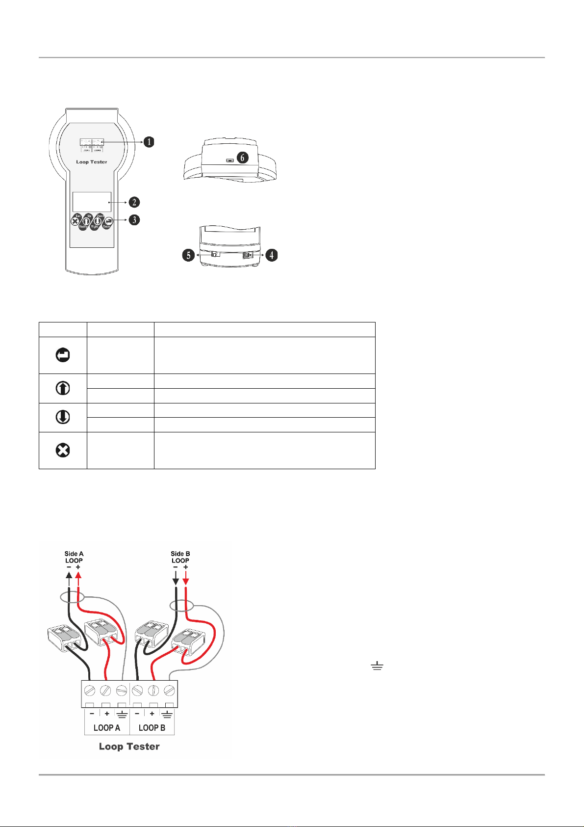
2. Control and Operation Elements ......................................................................................................................4
2.1. Control Unit......................................................................................................................................4
2.2. Buttons’ Functionality........................................................................................................................4
3. Connection Diagrams.......................................................................................................................................4
3.1. Loop Connection..............................................................................................................................4
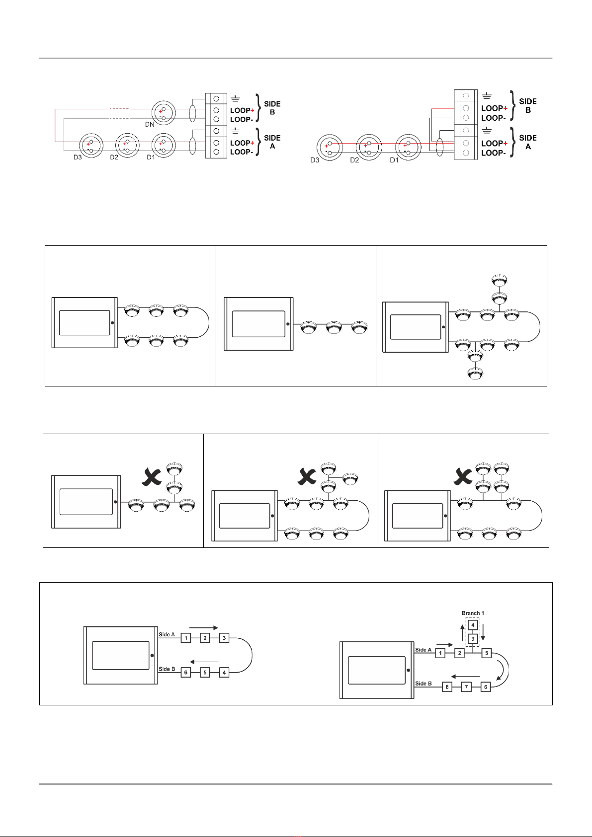
3.2. Topology Diagrams ..........................................................................................................................5
4. Operation with the Loop Tester........................................................................................................................6
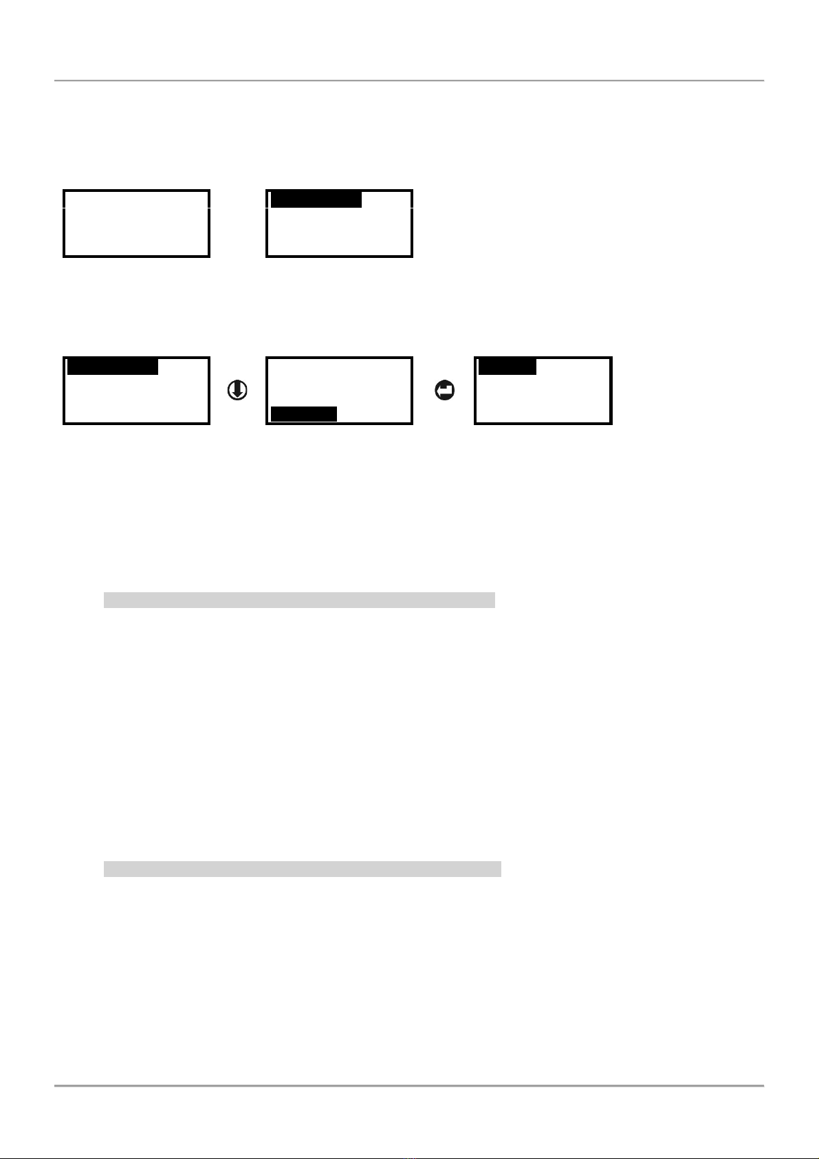
4.1. Switching on the Tester....................................................................................................................6
4.2. Choosing a Language.......................................................................................................................6
4.3. Reading a Topology of a Loop/Line ..................................................................................................6
4.3.1 Reading of Unaddressed Loop/Line (New installations)......................................................6
4.3.2 Reading of Addressed Loop/Line (Present installations).....................................................6
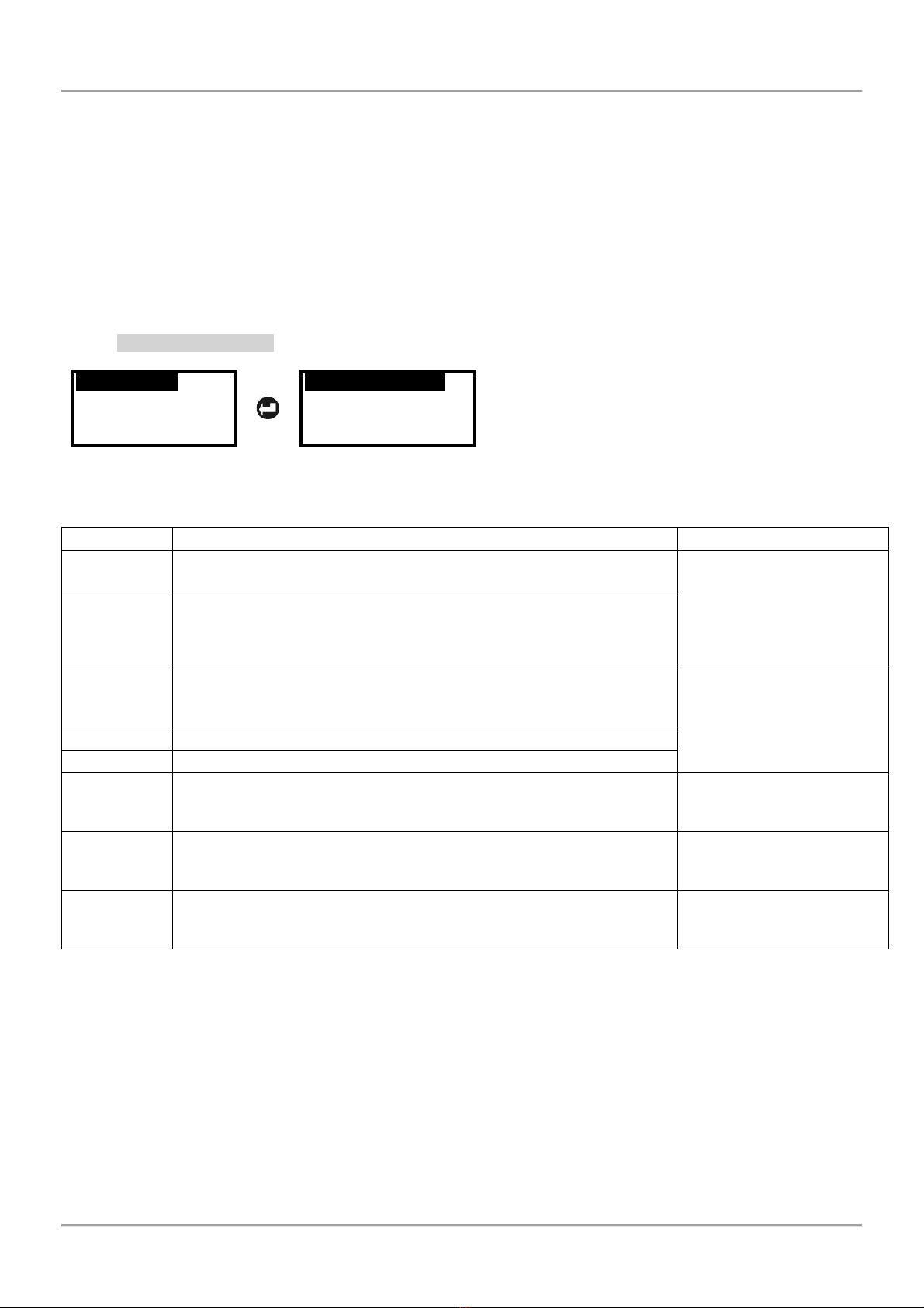
4.4. Perform Cable Tests.........................................................................................................................7
4.4.1 Auto Cable Test.................................................................................................................7
4.4.2 Single Cable Test...............................................................................................................8
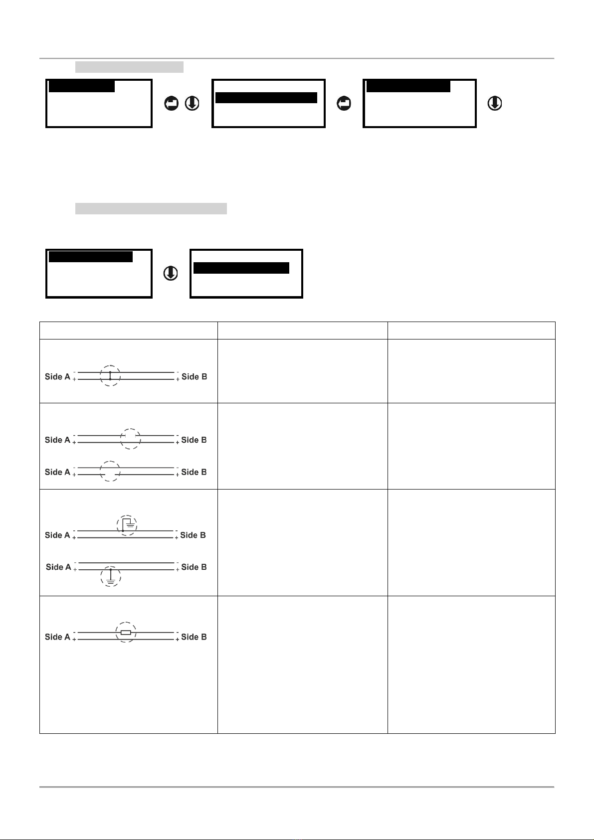
4.4.3 Searching for Cable Faults.................................................................................................8
4.5 Perform Loop Tests...........................................................................................................................9
4.5.1 Loop State.........................................................................................................................9
4.5.2 Loop Tools.......................................................................................................................10
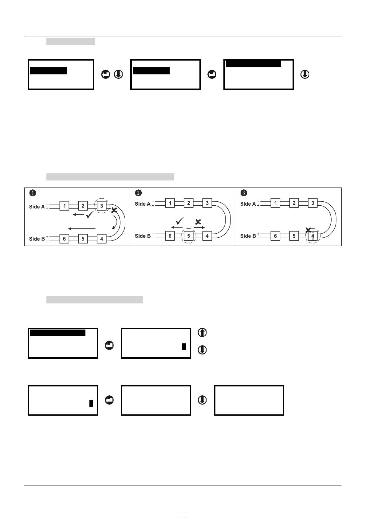
4.5.3 Bisection Method for Faults Searching .............................................................................10
4.5.4 Reading Device Parameters.............................................................................................10
4.5.5 Searching Short / Break Faults.........................................................................................11
4.5.6 Searching of Devices in Fire Alarm Mode.........................................................................12
4.5.7 Searching for Branch Position..........................................................................................12
4.5.8 Turn ON/OFF Device LEDs/Sound...................................................................................12
4.5.9 Checking the Operation Current.......................................................................................13
4.6 Addressing Devices Menus .............................................................................................................13
4.6.1 Autoaddressing by ID Number..........................................................................................13
4.6.2 Autoaddressing by Isolator Module...................................................................................14
4.6.3 Selfaddressing of Devices................................................................................................14
4.6.4 Changing the Address of a Device ...................................................................................14
5. Quick Menu Structure....................................................................................................................................15
Appendix –SensoIRIS Devices..........................................................................................................................15

Loop Tester –Technical and Operation Manual
3
1. Introduction
1.1. General Description
The Loop Tester is a diagnostic tool specially designed for operation with addressable devices SensoIRIS series.
The device is suitable for testing the continuity and the technical characteristics of the fire cable and also the
operability of the loop and the connected devices.
The Loop Tester can operate with only one loop line. The switching between the loops of the panel is very easy
using the supplied clamp terminal blocks.
The time for test may vary according the length of the loop and the number of the connected devices.
Important notes:
•During the test the loop line must be disconnected from the control panel!
•DO NOT connect the fire control panel and the Loop Tester to the loop line simultaneously!
•The cable tests have to be done without connected devices to the loop line! If the cable tests are
made with connected devices, you must consider that the measured results would not be exact.
•For exact results in searching short circuits faults, breaks in the loop line and existing branches is
mandatory all devices in the loop/line to be with built-in isolator module –see the corresponding
table for SensoIRIS addressable devices in the Appendix.
•In case of installed devices without isolators in present operating fire alarm systems, you have to
consider that they will be displayed as separate branches in the system. When you have to search
for branches in a system including devices without connected isolator, we recommend to remove
them temporally before starting mentioned above test procedures.
1.2. Technical Specification
•Main Power Supply: AC/DC Switching Adapter; input 100-240VAC, 50/60Hz, 1.5A; output 15VDC, 4A, 60W
•Range of the addresses: 1 ÷ 250
•Multilanguage Menus: YES
•Dimensions: 225 x 102 x 65 mm
•Weight: 340g
•Housing material, color: ABS, white
•Nominal Operating Temperature: -5°C ÷ 40°C
•Storage temperature: -20°C ÷ +70°C
•Related Humidity: ≤93% @ +40°C
1.3. Supplied Equipment in the Kit
•Loop Tester Unit –1 pc
•Power supply adapter –1 pc
•2-Cage clamp connector terminal block with levers –4 pcs
•Conductor wire, red, 120mm, 1.5mm2–2 pcs
•Conductor wire, black, 120mm, 1.5mm2–2 pcs
1.4. Preparing the joint connections
The Loop Tester is delivered with a set of wires (2 red and 2 black) and clamp terminals for easier connection to the
loop line. You can prepare the joint connections in advance and then follow the description in item 3. Connection
diagrams. Use conductor wires with cross-section from 0.14 to 4.00 mm².
Strip the wire to 11 mm length.
Lift the lever to open the clamp block.
Insert the stripped wire.
Push the lever backwards to close
the clamp block.

Loop Tester –Technical and Operation Manual
4
2. Control and Operation Elements
2.1. Control Unit
View from above
1 –Terminal block for connection to the loop line.
2 –LCD text display.
3 –Operation control buttons.
4 –Socket for switching the external power supply adapter.
5 –ON/OFF power switch.
6 –Micro USB port for firmware and software updates.
View at the bottom
2.2. Buttons’ Functionality
Button
Function
Description
Enter
- Confirmation of set parameters.
- Starting a test or addressing procedure.
- Turn ON/OFF of device LED indication.
Up
- Scrolling up the menus.
Modify
- Increasing the numeric digit with one unit.
Down
- Scrolling down the menus.
Right (Move)
- Moving the cursor on left/right.
Esc
- Reject the set parameters.
- Exit (one step back) from a sub- or main menu.
- Cancelation of test or addressing procedure.
3. Connection Diagrams
3.1. Loop Connection
Attention:
The loop line must be disconnected from the control panel before
connection to the Loop Tester!
DO NOT connect the fire control panel and the Loop Tester to the
loop line simultaneously!
Connect the four ready joint connections (clamp terminal + wire) to the
terminal row of the Loop Tester as strictly observe the polarity.
Connect the loop ends (side A and side B) to the respective clamps
connected to the terminal row of the Tester. Connect the shield ends
of the loop wires to the GND ( ) terminals of the Tester.
In case of a connection to a single line, connect to the Loop Side A
terminals of the tester, and use bridge connections along to Loop side
B terminals.

Loop Tester –Technical and Operation Manual
5
The following pictures represent a loop and single line connection to the Loop Tester terminal rows.
Loop connection
Single Line Connection
3.2. Topology Diagrams
The following topology types are allowed to be used for connection of SensoIRIS series addressable devices:
Loop
Single line
Loop with branches
The following topology types are not allowed to be used for connection of SensoIRIS series addressable devices. In
case of such connection found in the connection loop/line during addressing procedeure by isolator (see item 4.6.2),
the Loop Tester will display an error message “Branch in Branch” and will abort the operation.
Branch on a single line
Sub-branch of a branch on a loop
Branches without separation
In case of starting a test procedure of an unaddressed loop, the Loop Tester will set sequential addresses to the
devices according their order in the loop:
Addressing order in a loop
Addressing order in a loop with branch

Loop Tester –Technical and Operation Manual
6
4. Operation with the Loop Tester
4.1. Switching on the Tester
Power on the Loop Tester with the switch (item 2.1, position 5) moving in ON position. The display will show for a
while the software version of the device and then will display the main operation menus.
SW ver: 1.2
Cable tests
Loop Tests
Addressing
Language
4.2. Choosing a Language
The default set language is English. To set other available language for the setting menus, use the down arrow
button to select Language menu and press ENTER button.
Cable tests
Loop Tests
Addressing
Language
Cable tests
Loop Tests
Addressing
Language
English
Български
Italiano
Español
Use the arrows to select the language and confirm the choice with ENTER button. The menus will automatically
switch to the new set language.
4.3. Reading a Topology of a Loop/Line
The Loop Tester operation (test and addressing procedures) always starts from Loop Side A to Loop Side B –see
item 3.1. A list with avaliable devices in the loop/single line is reviewed in menu Loop Tests –Loop State (see item
4.5.1). The devices are displayed as a list according their set address in the system.
4.3.1 Reading of Unaddressed Loop/Line (New installations)
The advantage of the Loop Tester is that it is possible to read and test the characteristics of the fire cable,
connections in a loop or a line, and the mounted addressable devices for the site in advance, before connection to
the fire alarm control panel. In new installations the connected devices have no set addresses and the technician
has to address them first to perform the loop testing.
To perform testing of a new installation (unaddressed devices) follow the steps:
1. Connect the loop/line wires to the Loop Tester terminals as described in item 3.1.
2. Switch on the Loop Tester.
3. Enter in menu “Loop Test” and choose sub-menu “Loop Tools”. Select a test and press ENTER.
4. Select the option “Unaddressed loop” and confirm. Starting the procedure, the Loop Tester will set
sequential addresses to the devices according their order in the loop.
Note: You can run the addressing procedure again and change the set addresses later, when the loop is finally
connected to the fire alarm control panel.
4.3.2 Reading of Addressed Loop/Line (Present installations)
Attention: When you use the Loop Tester for diagnostic of present and already operating fire alarm
installation, it is strongly recommended first to save the existing configuration using specialised ProsTE
programming software!
To perform testing of a present installation (addressed devices) follow the steps:
1. Read the panel configuration with ProsTE software and save it as *TDF data file.
2. Power off the fire panel.
3. Disconnect the loop wires from the loop expander terminals.
4. Connect the loop/line wires to the Loop Tester terminals as described in item 3.1.
5. Switch on the Loop Tester.
6. Enter in menu “Loop Test” and choose sub-menu “Loop Tools”. Select a test and press ENTER.
7. Select the option “Addressed loop” and confirm.

Loop Tester –Technical and Operation Manual
7
4.4. Perform Cable Tests
This is a menu for performing test of the fire cable used in the installation. The test can be fully automatic or
manually selected separate single tests for different electrical values. It is recommended to run first the automatic
test for reviewing the general state of the cable and then, if it is necessary, to proceed with single tests.
The performed tests are for searching breaks, short circuits or earth fault of installed cable, which can disturb the
operability of the loop line.
Attention: The tests must be performed with no connected devices to the cable. If there are connected
devices, they have to be disabled or dismounted before running the desired tests.
Select Cable test menu and confirm with the ENTER button. Then choose auto or single cable test.
4.4.1 Auto Cable Test
Cable tests
Loop Tests
Addressing
Language
Auto Cable test
Single Cable test
Select this sub-menu to perform fully automatic test of the electrical characteristics of the cable. While the test is
running on, the message “Please Wait” is shown on the display. The time for test may vary according the length of
the cable.
The results from the test are shown as a list with values and can be reviewed (scrolling up/down) with arrow buttons:
Value
Description
Range limits/Messages
Ua
Measured voltage from the Loop side A. The side A is powered on and
then the voltage is measured at the same side of the loop.
15-32V
Ub
Measured voltage from the Loop side B. The side A is powered on,
then the side B is powered on and the voltage is measured at side B of
the loop. The measurement gives an idea for the voltage drops (from
side A to side B), electrical current value and cable resistance.
R+
The resistance of the positive cable wire. In case “Too High” message
is displayed that means there is a break in the cable or a bad contact
in the joint connections.
< 250 Ohm –Normal
250 - 400 Ohm –High
> 400 Ohm –Too High
(see item 4.4.3)
R-
The resistance of the negative cable wire. Same as described for “R+”.
Re
The resistance of the earth cable. Same as described for “R+”.
Earth Fault
Shows the presence of earth fault problem (or leakage to earth) of the
positive or negative wire of the cable* (see item 4.4.3).
None –No fault
Yes –Earth fault detected
in the cable
Short in cbl.
Shows the presence of short-circuit fault between the positive or
negative wire of the cable* (see item 4.4.3).
None –No fault
Yes –Short-circuit fault
with the cable
Break in cbl.
Shows the presence of breaking in the cable* (see item 4.4.3).
None –No fault
Yes –Break fault with the
cable
* Note: Use the bisection method for finding and location of the exact place of the fault. The method is described in
item 4.5.3.

Loop Tester –Technical and Operation Manual
8
4.4.2 Single Cable Test
Cable tests
Loop Tests
Addressing
Language
Auto Cable test
Single Cable test
Voltage side A
Voltage side B
R+ Cable
R- Cable
In “Single Cable test” sub-menu, all cable tests (see the table in item 4.4.1) are manually selected and performed
according the current needs of the technician. You can scroll with up and down arrow buttons to review the rest of
the possible test. The selected test is started with pressing ENTER button. To reject a started test press ESC button.
To escape from the “Cable Tests” menus press ESC button several times.
4.4.3 Searching for Cable Faults
If an error message is displayed in “Auto Cable Test” menu, you can run the separate single test again and locate
the exact place of the fault. Select a test using the arrows and run it with ENTER button.
Voltage side A
Voltage side B
R+ Cable
R- Cable
R Earth Cable
Leakage to Earth
Test for Short
Test for Break
Fault Diagram
Description
Solution
Short-circuit in the cable
Run singe test “Test for Short”
again to confirm the presence
short-circuit in the cable. In case of
fault the tester will display message
“Short in Cable”.
To locate the place of the short-
circuit fault use Bisection method
as dividing the cable in equal parts
(1/2, 1/4, 1/8, etc), until finding the
faulty section. See also item 4.5.3.
Break in the cable
Run singe test “Test for Break”
again to confirm the presence
break in the positive or negative
cable wire. In case of fault the
tester will display message “Break
in Cable”.
To locate the place of the break
use Bisection method as dividing
the cable in equal parts (1/2, 1/4,
1/8, etc), until finding the faulty
section. See also item 4.5.3.
Earth fault in the cable
Run singe test “Leakage to Earth”
again to confirm the presence earth
fault in the positive or negative
cable wire. In case of fault the
tester will display message “Earth
fault”.
Search the earth fault as inspect
the grounding components in the
cable line, corrupted shield of the
cable, etc.
You can also use and the Bisection
method described in item 4.5.3.
Too High resistance
According the result in the Auto
Cable Test menu run the single test
for:
“R+ Cable”
“R- Cable”
“R Earth Cable”
In case of unusual high resistance
found the tester will display
message “R+/R-/Re=Too High”.
The error message “Too High” is
displayed when the detected
resistance in the positive cable
wire (R+), negative cable wire (R-)
or earth cable (Re) is higher than
400 Ohm. In such cases, it is
recommended to check the cable
and the joint connections
(terminals, base contacts). Check
also the cable length –it might be
too long.

Loop Tester –Technical and Operation Manual
9
4.5 Perform Loop Tests
This is a menu for performing test of the loop and the connected devices. It is recommended to run first the “Loop
state” automatic test for reviewing the general state of the loop and a list of the connected devices. The general
review will help you at the beginning to orientate for current faults, possible breaks or short-circuits in the loop, the
number of connected devices and troubles with them.
Attention: To perform more precise tests it is obligatory to use the built-in isolator module for all modules
and call points connected to the loop. It is recommended to use detectors and sounders with bult-in isolator
module (see the table in the Appendix). In installations where, detectors and sounders without built-in
isolators are already being used, the results for searching branches and localization of short-circuits and
break in the loop can be uncertain. In this case it is recommended for more precise results in searching of
errors to be performed and the bisection method (see item 4.5.3).
4.5.1 Loop State
Cable tests
Loop Tests
Addressing
Language
Loop State
Loop Tools
Select “Loop State” menu and press ENTER. The message “Please wait” and a process bar are shown during
analysing the current loop state. The time for reading data can vary according the length and the number of
connected devices.
The general information is displayed as a list with short messages for the state and can be reviewed (scrolling
up/down) with arrow buttons:
Parameter
Description
State Messages
Short Side A
Shows the presence of short circuit at Loop Side A. In case of
fault “Yes” message, you can perform a detailed search using
menu “Loop Tools” – “Short / Break” (see item 4.5.5).
None –No fault
Yes –Short circuit detected at
side A.
Short Side B
Shows the presence of short circuit at Loop Side B. In case of
fault “Yes” message, you can perform a detailed search using
menu “Loop Tools” –“Short / Break” (see item 4.5.5).
None –No fault
Yes –Short circuit detected at
side B.
Earth Fault
Shows the presence of earth fault in the loop.
None –No fault
Yes –Earth fault detected.
Loop Break
Shows the presence of break in the loop. In case of fault “Yes”
message, you can perform a detailed search using menu “Loop
Tools” – “Short / Break” (see item 4.5.5).
None –No fault
Yes –Loop break detected.
Noaddr. Dev.
Shows the presence of devices with no set address in the loop.
Note: A possible reason for presence of devices with no set
address is performing the Loop State test for an unaddressed
loop.
None –No unaddressed devices
XXX –Number of found
unaddressed devices
Dbl. address
Shows the presence of devices with double address in the loop.
None –No double addresses
XXX –Number of found double
addresses
Num devices
Shows the current number of the addressed devices in the
loop.
Note: The number of unaddressed devices and devices with
double address are not included into this number.
XXX –Number of addressed
devices
Op. curr.
Shows the operating current of the loop. This is average
consumption of the connected devices.
Up to 500mA
Devices Table
Shows a list of the available devices and their set address in the
system. Note: The found devices with double address are listed
at the bottom of the table. The presented numbers for them are
not real addresses. In this case is recommended to perform an
addressing procedure for the loop and run the Loop State test
again.
-

Loop Tester –Technical and Operation Manual
10
4.5.2 Loop Tools
In this menu are available some test for finding troubles in existing loop installation.
Cable tests
Loop Tests
Addressing
Language
Loop State
Loop Tools
Read parameters
Short / Break
Fire position
Branch position
In the “Loop Tools” menu are included the following operations for precise finding of troubles and devices in the loop
configuration. You can scroll with up and down arrow buttons to review the rest of the available operations:
•Read parameters
•Short / Break
•Fire position
•Branch position
•Turn ON/OFF
•Operation current
4.5.3 Bisection Method for Faults Searching
1. Divide the loop into two separate equal lines. Measure the voltage at each line.
2. Divide the faulty line in the center. Restore the earlier connection in the correct line. Measure again the voltage at
each line. Thus, you will be able to locate the fault section.
3. Proceed in this way of dividing the faulty section in the center reducing the possible area with fault.
4.5.4 Reading Device Parameters
The “Read parameters” menu is for reviewing the type and some specific information for a device. Select “Read
parameters” and press ENTER button. Then using the arrows enter an address number - the buttons functionality is
described in item 2.2.
Read parameters
Short / Break
Fire position
Branch position
Read parameters
Enter Address 001
- Increasing values with one unit.
- Move the cursor between digits.
To read the parameters for the device of the selected address press ENTER button. The screen displays the
following general information:
Read parameters
Enter Address 001
Type:
Address:
S.No:
SW version:
Address:
S.No:
SW version:
Day Night
•Type –The name of the device –refer to the table in the Appendix for more details.
•Address –The current set address of the device.
•S.No –The serial number of the device, unique 10 digits number.
•SW version –The software version of the device.
•Day/Night –This parameter is available for reviewing only for detectors. In the field is displayed the set
levels for Day and Night operation modes (Low/Normal/Medium/High).
To escape from the “Read parameters” menu, single press ESC button.

Loop Tester –Technical and Operation Manual
11
4.5.5 Searching Short / Break Faults
Attention: To perform accurate tests for finding of Short and Break position in the loop is mandatory all of
the devices in the loop to have a built-in isolator module!
The “Short / Break” menu is for searching the exact place of short-circuit or a break in the loop.
Read parameters
Short / Break
Fire position
Branch position
Addressed loop
Unaddressed loop
According the organization of the system configuration there are two approaches to start test:
•Addressed loop –Use this option, when the devices in the loop are with already set address numbers.
The searching will follow the set addresses in the loop and will display the faults according their order.
•Unaddressed loop –Use this option, when all or some devices are undressed. Before starting the test,
the tester will erase the current addresses and will set new to all devices according the ID number.
After choosing an approach to proceed the tester starts consistent tests for short-circuit and break faults. The test is
started with pressing the ENTER button. During analysing, a message “Please wait” and a process bar are displayed
on the screen. The time for analysing can vary according the length of the loop and the number of faults.
The results are displayed with text messages pointing the place of the fault. Below is presented a quick table for
possible faults.
Fault Diagram
Description and Display
Solution
Short-circuit in the loop
A short-circuit is detected between
devices 2 and 3 in the loop.
Short at:
Dev.Type 002
Dev.Type 003
Locate the place of the displayed
devices and check the cable
section between them.
Tip: You can locate the exact place
of a device as turning ON its LEDs
(or sound signal for sounders) –
see item 4.5.8.
Break in the loop
A break in the loop is detected
between devices 2 and 3 in the
loop. The tester will locate the place
searching from both sides A and B.
Break between:
002 dev from SideA
004 dev from SideB
Find location >>>
The displayed numbers are the
counted devices from the two sides
of the found break. To find the
exact location of the break fault,
press ENTER button and confirm
with “Yes” command to continue.
When the test is over, the screen
displays the address of the device
after which the break is detected.
Break after:
Dev.Type 002
Locate the place of the displayed
devices and check the cable
section between them. The break
in the loop may be caused and
from bad connections to the device
terminals (bad joint contacts to the
base terminals for detectors and
sounders also).
Tip: You can locate the exact place
of a device as turning ON its LEDs
(or sound signal for sounders) –
see item 4.5.8.

Loop Tester –Technical and Operation Manual
12
4.5.6 Searching of Devices in Fire Alarm Mode
In this menu the technician can review if there an activated manual call points in the system. The test can be
performed for checking the correct operation of the connected call point to loop. Select “Fire position” and press
ENTER button. During the analysing process a message “Please wait” and a processing bar are displayed on the
screen. If there are activated manual call points, they will be displayed with their address number.
Read parameters
Short / Break
Fire position
Branch position
Devices in fire:
MCP150 008
MCP150 055
To escape from the “Fire position” menu, single press ESC button.
4.5.7 Searching for Branch Position
The branch is a sub-loop to the main loop. The connection topology diagrams are presented in item 3.2.
Attention: To perform accurate localization of the Branch position in the loop is mandatory all of the devices
in the loop to have a built-in isolator module!
In case of presence of devices without isolator, after performing this test they will be reported with type and
address and the branch search will be cancelled. For this reason, the devices without isolator, if present at
the site, must be removed in advance, before performing branch searching.
The presence of Short circuit and Break in the loop will generate an error message and the branch
searching process will be aborted.
Select “Branch position” and press ENTER button. During the analysing process a message “Please wait” and a
processing bar are displayed on the screen. The tester starts searching and during the test will show the total
number of addressed devices found in the loop (note that if a device is removed temporally it will not be included into
this number). At the last row is presented the real time searching as the tester goes through the loop devices.
At the final results screen are displayed the total number of found branches followed by the location where the first
one starts and the number of included devices into it. If there is more than branch into the loop, the list can be
reviewed with the arrow buttons.
Read parameters
Short / Break
Fire position
Branch position
Analysing...
Total devices in
Loop: 055
Started dev.: 001
Numb branches 001
001 Branch at:
M140 IS 003
Dev.in branch:002
Example for representing the described configuration above:
The Branch 001 is started with detector with set address 003, and
includes 2 devices in total (addresses 003 and 004).
You can locate the exact place of all devices included into the branch as
turning ON their LEDs (or sound signal for sounders), starting with the
first one displayed with the tester –see also item 4.5.8.
Note: In real installation the addresses may not be in consecutive order
as displayed in the example. It is recommended when searching for
branches to refer also to the electrical schematic diagrams of the built
fire alarm installation at the site.
4.5.8 Turn ON/OFF Device LEDs/Sound
This is a menu for location of exact place of a device in a fire installation with switching ON its LEDs (or sound signal
for sounders). From the main “Loop tools” menu use down arrow to select the “Turn ON/OFF” sub-menu and press
ENTER button.
Read parameters
Short / Break
Fire position
Branch position
Fire position
Branch position
Turn ON/OFF
Operating current
Turn ON/OFF
Enter address 000
Increasing values
with one unit.
Move the cursor
between digits.

Loop Tester –Technical and Operation Manual
13
Use the arrow buttons to select and address of a device and press ENTER button. A field “Turn ON” is appeared on
the screen. Press ENTER button again to activate the LED indication of the device. The field is changed to “Turn
OFF” and the LEDs of the device are switched on*.
Turn ON/OFF
Enter address 001
Turn ON
Turn ON/OFF
Enter address 001
Turn OFF
To switch off the LED indication press the ENTER button again –the field is changed to “Turn ON”. To select new
address for check, press ESC button –the field “Turn ON” is removed and the section for entering and address
starts blinking waiting new number to be entered.
*Note: For sounders with strobe, together with the LEDindication is switched on and a sound signal. For sounders
without strobe option is turned on only sound signal.
To escape from the “Turn ON/OFF” menu, single press ESC button.
4.5.9 Checking the Operation Current
This is a menu for checking the operation current in the loop –the average consumption of the connected devices in
the loop. The maximum current consumption of the devices in the loop is Imax = 500mA. If the consumption
exceeds this value an over-load protection would be turned on.
Read parameters
Short / Break
Fire position
Branch position
Fire position
Branch position
Turn ON/OFF
Operating current
Op.curr.= 120 mA
To escape from the “Operating current” menu, single press ESC button.
4.6 Addressing Devices Menus
In the “Addressing” section are accessible menus for different type of addressing devices in the loop. The menus are
common with those available in IRIS/SIMPO fire alarm panels. The menus allow performing two auto addressing
procedures by ID number or by isolator module (IS). The self-addressing procedure is used for quick adding of new
devices to free addresses. The last menu is for quick changing the current address of a device.
Cable tests
Loop Tests
Addressing
Language
Autoaddressing ID
Autoaddressing IS
Selfaddressing
Change address
Attention: Performing the auto addressing procedures by ID number and by Isolator module, will erase all
currently set address numbers of the devices in the loop.
4.6.1 Autoaddressing by ID Number
The addressing procedure follows the order of the ID numbers of the devices connected to the line. The order is
according the device type starting with the smallest ID number in the loop: modules, sounders, detectors and manual
call points. It is possible to address devices with and without built-in isolator modules. No restrictions for addressing
detectors into branches.
Select “Autoaddressing ID” menu and press ENTER button. To start the procedure, select “Yes” option and press
ENTER again.
Autoaddressing ID
Autoaddressing IS
Selfaddressing
Change address
Autoaddressing ID
Are you sure?
No
Yes
Autoaddressing ID
Successful
Number addressed
Devices: XXX
After successful addressing a message “Successful” will appear on the screen followed from the total number of
addressed devices. The order of addressing can be reviewed in “Loop State” menu –see item 4.5.1.
To escape from the “Autoaddressing ID” menu, press ESC button.

Loop Tester –Technical and Operation Manual
14
4.6.2 Autoaddressing by Isolator Module
This way requires all of the devices connected to the line to have a built-in or connected to the loop isolator module.
The tester starts the addressing of devices according their place following the order in the loop from side A to side B
–see item 3.1. There are some restrictions for addressing the detectors included into branches –see item 3.2.
Select “Autoaddressing IS” menu and press ENTER button. To start the procedure, select “Yes” option and press
ENTER again. During the addressing procedure, the screen displays the current number of found addressed devices
and the number of found branches.
Autoaddressing ID
Autoaddressing IS
Selfaddressing
Change address
Autoaddressing IS
Are you sure?
No
Yes
Successful
Addressed
Devices: 055
Nmb.branches: 001
After successful addressing a message “Successful” will appear on the screen followed from the total number of
addressed devices and the total number of found branches. The order of addressed devices can be reviewed in
“Loop State” menu – see item 4.5.1. The branch position can be reviewed in “Loop Tools” menus – see item 4.5.7.
Note: The addressing can be unsuccessful in case of found devices without isolator in the loop. In this case a fault
message “Branch in branch” will display on the screen and the addressing is aborted. It is recommended before
starting addressing by isolator module first to remove the devices without isolator module from the loop.
To escape from the “Autoaddressing IS” menu, press ESC button.
4.6.3 Selfaddressing of Devices
During this addressing procedure, the devices are added one by one to the loop (currently the detectors and
sounders are not mounted to the bases; the call points and modules are not connected to the loop).
Select “Selfaddressing” menu and press ENTER button. The tester will starts checking the current configuration as
during the process a message “Please wait” and a processing bar are displayed on the screen. When the reading is
complete the screen displays the total number of found addresses and the next free address in the system.
Autoaddressing ID
Autoaddressing IS
Selfaddressing
Change address
Selfaddressing
Dev. in loop: 055
Next address: 056
Ent. to start
Selfaddressing
Dev. in loop: 055
Next address: 056
ESC to stop
Press ENTER button to begin selfaddressing. Start to mount detectors one by-one. The tester will set the displayed
address number to the mounted device and automatically proceeds with next free address in the system. Every
device will confirm the new set address: with LED indication and/or with sound signal for sounders.
When all the new devices are added press ESC button to stop the procedure.
4.6.4 Changing the Address of a Device
In this menu the technician can change the current address of a device.
Select “Change address” menu and press ENTER button. The tester will starts checking the current configuration as
during the process a message “Please wait” is displayed on the screen. When the reading is complete the screen
displays two fields for setting the current address and the new address for the device. Use arrow buttons to set
address for changing and press ENTER button. The field “Set new addr” becomes active. Set the new address and
press ENTER to confirm.
Autoaddressing ID
Autoaddressing IS
Selfaddressing
Change address
Change address
Current addr: 001
Set new addr:
Change address
Current addr: 001
Set new addr: 009
After successful changing a message “Successful” will appear on the last row of the screen.
If “Busy new address” message is displayed on the last row that means the selected new address is already used in
the system configuration. In that case press ESC button to start the procedure again.
If “No device at:” message followed from an address number is displayed, that means no real device is found on the
current set address. In that case press ESC button to start the procedure again.

Loop Tester –Technical and Operation Manual
15
5. Quick Menu Structure
Appendix – SensoIRIS Devices
Device Name
Description
Isolator Module Available
S130
Optical-smoke detector
No
S130 IS
Optical-smoke detector
Yes (built-in)
T110
Temperature detector
No
T110 IS
Temperature detector
Yes (built-in)
M140
Combined detector
No
M140 IS
Combined detector
Yes (built-in)
MCP150
Manual call point
Yes (must be connected during installation)
WSOU
Sounder
No
WSOU IS
Sounder
Yes (built-in)
WSST / WS
Sounder and strobe
No
WSST IS / WS IS
Sounder and strobe
Yes (built-in)
BSOU
Base with sounder
No
BSOU IS
Base with sounder
Yes (built-in)
BSST
Base with sounder and strobe
No
BSST IS
Base with sounder and strobe
Yes (built-in)
MIO 04
Module with 4 outputs
Yes (must be connected during installation)
MIO 40
Module with 4 inputs
Yes (must be connected during installation)
MIO 22
Module with 2 inputs/2 outputs
Yes (must be connected during installation)
MIO 22M
Module with 2 inputs/2 monitored outputs
Yes (must be connected during installation)
MOUT
Module with 1 output
Yes (must be connected during installation)
MOUT-240
Module 240V interface with 1 output
Yes (must be connected during installation)
MINP M
Mini module with 1 monitored input
No
MC-Z
Conventional zone module
Yes (must be connected during installation)
Table of contents
Popular Test Equipment manuals by other brands

Agilent Technologies
Agilent Technologies 54621A user guide

Agilent Technologies
Agilent Technologies Infiniium 90000 Q-Series user guide

Megger
Megger TDM 45-P user guide

VOLTCRAFT
VOLTCRAFT MS-100 operating instructions

IBEKO POWER
IBEKO POWER DV-Power TRT3A manual

Berner
Berner Profi LCD Plus II operating instructions

Hygiena
Hygiena foodproof 2300 92 manual

Apera Instruments
Apera Instruments SX610 user manual

R&S
R&S HMO72 Series installation guide

RS PRO
RS PRO RSHS800 Series quick start

Omega Engineering
Omega Engineering hot point CL900A Series user guide

Good Will Instrument
Good Will Instrument instek GOS-6200 user manual