Wolfgang Warmbier GmbH & Co. KG 7
2 Safety Features and Precautions
The electronic measuring and test instrument is manufactured
and tested in accordance with safety regulations IEC/EN 61010-
1/VDE 0411-1 and EN 61557. When used for its intended pur-
pose, safety of the operator, as well as that of the instrument, is
assured.
Read the operating instructions thoroughly and carefully before
using your instrument. Follow all instructions contained therein.
The measuring and test instrument may not be placed into
service:
• If the battery compartment lid has been removed
• If external damage is apparent
• If connector cable or measuring adapters are damaged
•Iftheinstrumentnolonger functions flawlessly
• After extraordinary stressing due to transport
• After a long period of storage under unfavorable conditions
(e.g. humidity, dust or extreme temperature)
Data Backup
We advise you to regularly transfer your stored data to a PC in
order to prevent potential loss of data in the test instrument.
We assume no responsibility for any data loss.
We recommend ETC software (Electric Testing Center) for back-
ing up, processing and managing data.
Meanings of Symbols on the Instrument
Warning concerning a point of danger
(attention, observe documentation!)
Protection class II device
Charging socket for extra-low direct voltage (Z502R
charger)
Attention!
Only rechargeable batteries may be inserted when the char-
ger is connected.
EC mark of conformity
The device and included batteries may not be dis-
posed of with the trash.
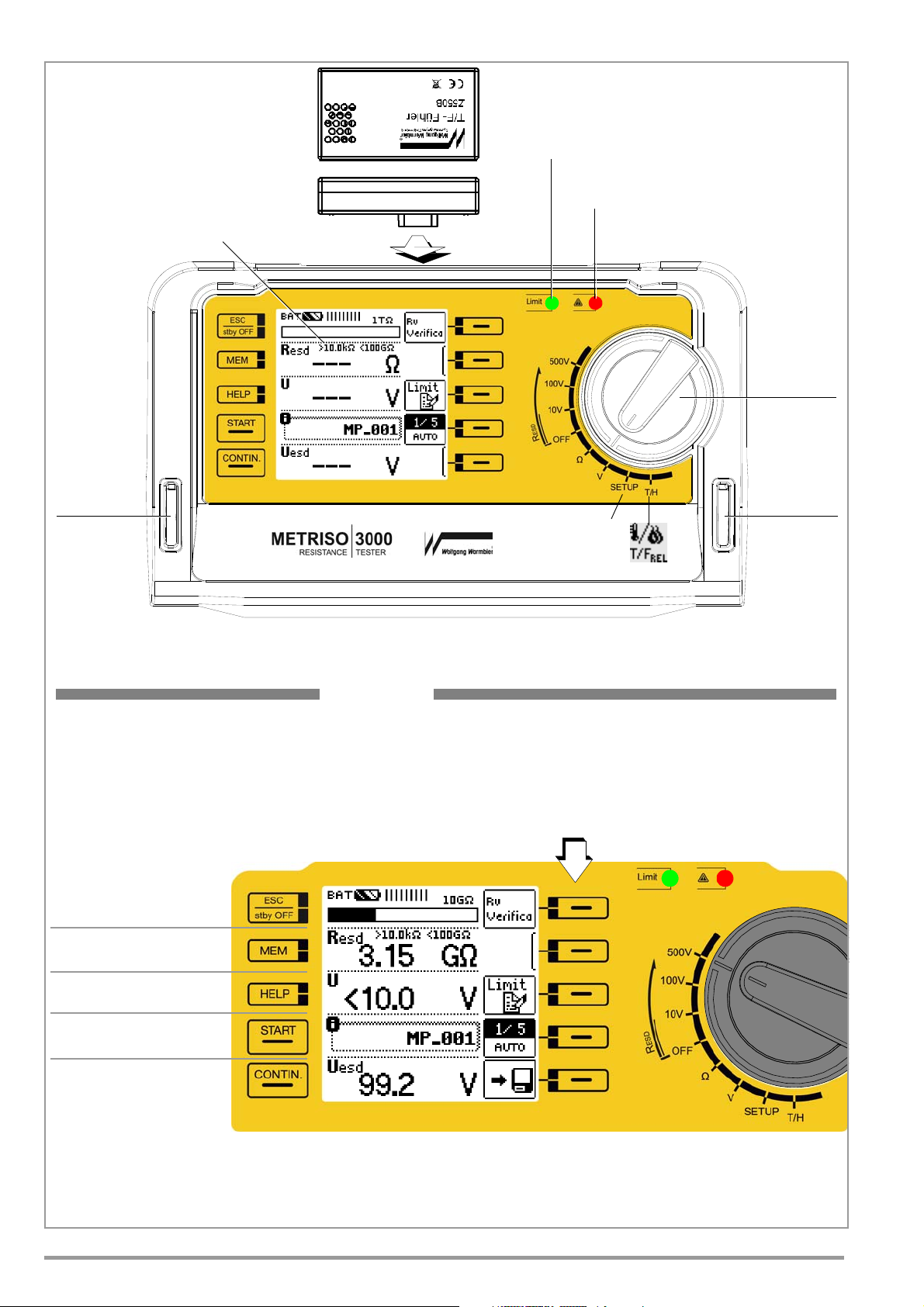
3 Initial Start-Up
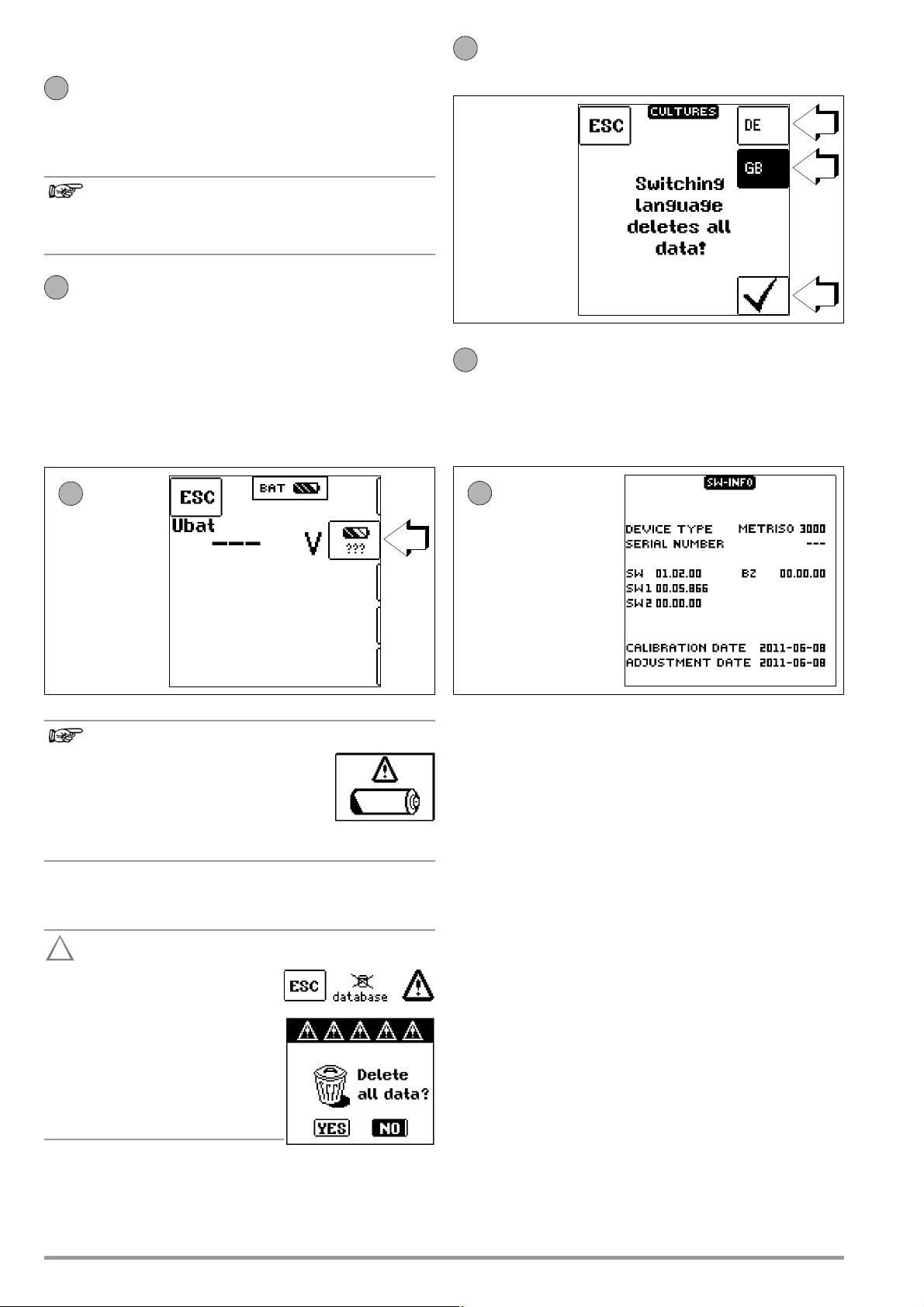
3.1 Battery Test
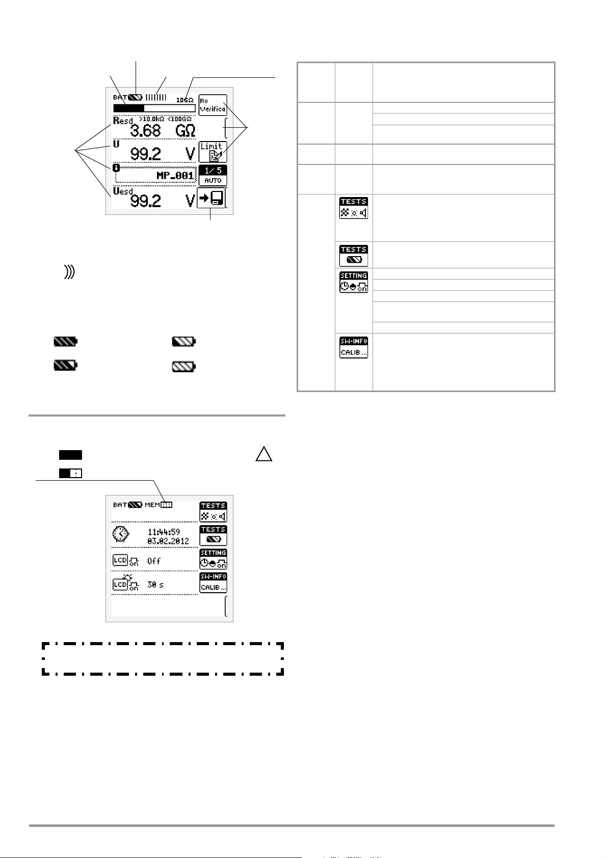
Four different battery symbols, ranging from fully depleted to fully
charged, continuously indicate the momentary charge level in the
upper left-hand corner of the display
If battery voltage has fallen below the allowable lower
limit, the pictograph shown at the right appears. The
instrument does not function if the batteries have been depleted
excessively, and no display appears.
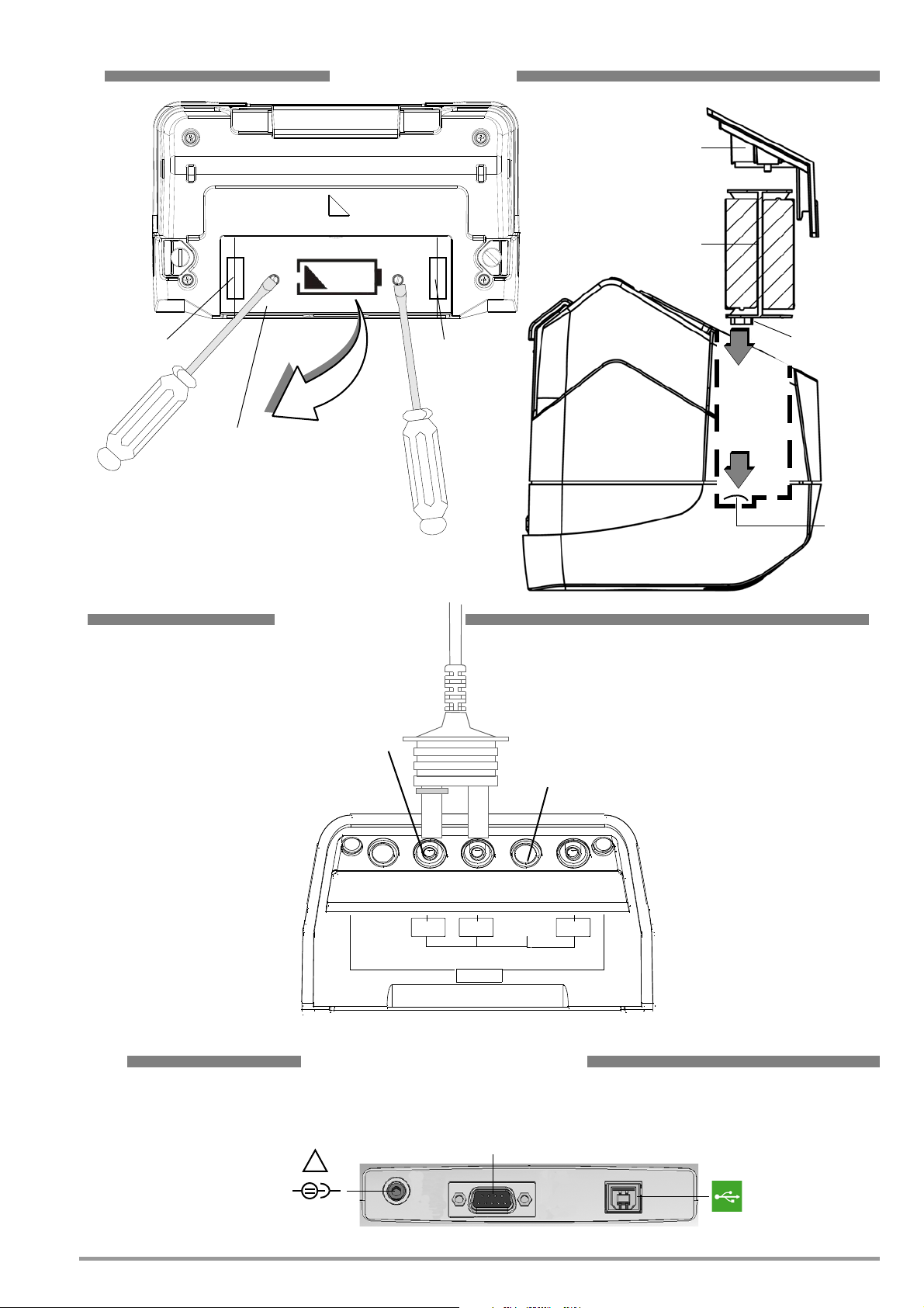
3.2 Installing or Replacing Batteries
New batteries must be inserted for initial start-up, or if only 1 filled
segment remains in the battery symbol.
Before opening the battery compartment (see page 5 for
location), disconnect the instrument from the measuring
circuit (mains) at all poles.
Eight 1.5 V size AA batteries in accordance with IEC LR 6 are
required for operation of the high-impedance measuring instru-
ment. Use new alkaline manganese batteries only.
Rechargeable NiCd or NiMH batteries may also be used. These
can be charged externally or by connecting the Z502R charger to
the test instrument. We recommend rechargeable NiMH batteries.
Always replace batteries in complete sets.
Dispose of batteries in an environmentally sound fashion.
➭Loosen both slotted screws for the battery compartment lid
on the back, and remove the lid.
➭Remove the battery holder and insert eight 1.5 V size AA bat-
teries with correct polarity in accordance with the symbols.
Make sure that all of the batteries are inserted with correct
polarity. If just one battery is inserted with reversed polar-
ity, it will not be recognized by the instrument and may
result in leakage from the batteries.
➭Push the battery holder into the battery compartment such
that the battery holder’s contacts touch the contact springs at
the bottom of the battery compartment (see drawing on
page 3).
If the battery holder is not inserted as specified, the instrument
cannot be supplied with power.
➭Replace the battery compartment lid and retighten the
screws.
The instrument may only be placed into service if the
battery compartment lid is securely fastened!
3.3 Charging the Batteries in the Tester
Use only the Z502R charger (available as an accessory)
to charge batteries which have already been inserted into
the test instrument.
Make sure that the following conditions have been fulfilled be-
fore connecting the charger to the charging socket:
– Rechargeable batteries have been installed with
correct polarity (not standard batteries)
– The test instrument has been disconnected from the
measuring circuit at all poles
– The instrument must remain off during charging.
Refer to section 12.2.1 with regard to charging batteries which
have been inserted into the tester.
If the batteries or the battery pack have not been used or
recharged for a lengthy period of time (> 1 month), thus resulting
in excessive depletion:
Observe the charging sequence (indicated by the LED at the
charger) and initiate a second charging sequence if necessary
(disconnect the charger from the mains and from the test instru-
ment to this end, and then reconnect it).