Tenma 72-7910 User manual

DigitalStorageOscilloscope
Model:72‐7610/72‐10510

TableofContents
Ⅰ.SafetyInformation.....................................................................................................1
Ⅱ.Accessories....................................................................................................................2
Ⅲ.ProductOverview......................................................................................................2
Ⅳ.Functions........................................................................................................................3
1. GettoKnowtheUserInterface.........................................................................4
2. GeneralInspections............................................................................................5
3. FunctionInspections..........................................................................................6
4. ProbeCompensation..........................................................................................8
5. AutomaticSettingofWaveformDisplay............................................................9
6. IntroductiontotheVerticalSystem...................................................................9
7. IntroductiontotheHorizontalSystem............................................................10
8. IntroductiontotheTriggerSystem................................................................11
Ⅴ.Specifications.............................................................................................................12
A. TechnicalSpecifications.....................................................................................12
B. GeneralTechnicalSpecifications........................................................................17
Ⅵ.Operations....................................................................................................................18
1. SettheVerticalSystem......................................................................................19
2. SettheHorizontalSystem..................................................................................28
3. SettheTriggerSystem.......................................................................................30
4. SettheAcquireSystem......................................................................................37
5. SettheDisplaySystem.......................................................................................39
6. SettheStorageandLoadSystem.......................................................................41
7. SettheUtilitySystem.......................................................................................46
8. SettheMeasurementParameters.....................................................................51
9. SettheCursorMeasurement.............................................................................52
10. SystemMessageExamplesandTroubleshooting...............................................53
Ⅶ.Maintenance&Cleaning.....................................................................................55

Model72‐7610/72‐10510UserManual
1
Ⅰ.SafetyInformation
72‐7610/72‐10510oscilloscopesaredesignedandmanufacturedunderthesafety
requirementsofIEC61010‐1safetystandards,andconformstoinsulationand
overvoltagestandards,CATII(150Vor300Vdependingonprobesetting)andpollution
degreeIIsafetystandards.Pleasefollowprecautionsbelowinordertoavoidpersonal
injuries,productdamages,ordamagestoanyproductsconnectedwiththeinstrument.
Toavoidpossibledanger,pleaseoperateaccordingtodirectionsbelow.
Onlyprofessionalscanexecutethemaintenanceprocedure.
Preventfireandpersonalinjuries.
Usethededicatedpowerlinesrecognizedbyyourcountry.
Donotplugorunplugwhentheprobeortestleadhasbeenconnectedtovoltage
source.
Groundproductreliablytoavoidelectricalshock.Theproductsaregroundedvia
powerearthcord.Priortoconnectingtheinputoroutputterminalsoftheproducts,
makesuretheproductsaregroundedcorrectly.
Correctlyconnecttheoscilloscopeprobes.Theprobeearthcordandthegroundare
ofthesamepotential.Pleasedonotconnectthecordwithhighvoltagesource.
Checktheratedvaluesofallterminals.Toavoidfireandelectricalshock,please
checkallratedvaluesandremarksonproducts;beforeconnectingtheproducts,
checkratedvaluesinthemanual.
Donotopenthefrontpanelorbackcaseduringoperation.
Useproperfuses.Onlyusethespecifiedfusesofthesamespecifications.
Avoidcircuitexposure.Pleasedonotcontactwithexposedplugsorelementsafter
poweringon.
Stopoperatingwhenanyproductissuspectedtobeoutoforderandcanaskthe
qualifiedtechniciantoinspect.
Keepproperventilation.
Pleasedonotoperateinthehumidenvironment.
Pleasedonotoperateininflammableandexplosiveenvironments.
Pleasekeepproductsurfacecleananddry.
Symbolsonproducts:suchsymbolsmayappearonproducts.
Highvoltage
Pleasecheckthemanual
Protectivegroundterminal

Model72‐7610/72‐10510UserManual
2
Casegroundterminal
Measuringgroundterminal
Safetytermsandsymbols
Thetermsbelowmaybeinthemanual,
Warning:warningstatementsrefertoconditions
andactionsthatmayendangerlife.
Thetermsbelowmayappearonproducts,
Danger:indicatingthereisdirectdangerclosetothemarking.
Warning:indicatingthereispotentialdangerclosetothemarking.
Attention:indicatingthereispotentialdamagetotheproductandotherproperties.
Ⅱ.Accessories
Standardaccessories:
Twoprobes(selectablefor1:1and10:1).TheyconformtoEN61010‐031standards.
-Whentheswitchisin1×position,itbelongsto150VCATII.
-Whentheswitchisin10×position,itbelongsto300VCATII.
Onepowercord
Oneusermanual
OneoscilloscopecommunicationcontrolsoftwareCD
OneUSBCable
Optionalaccessories:
LANportmodule
Pleaseorderalltheaccessories(standardandoptionalaccessories)fromthelocal
distributors.
Ⅲ.ProductOverview
Thesedigitalstorageoscilloscopeprovidestheuserswithsimplefrontpaneltooperate
variousfunctions.Scaleandpositionknobsofeachchannelprovidevisualoperationsthat
areinlinewithusers’habits.Usersmaybeabletomasteritwithoutspendingplentyoftime
Attention:attentionstatementsreferto
conditionsandactionsthatmaycausedamages
totheproductorotherproperties.

Model72‐7610/72‐10510UserManual
3
learningandunderstanding.Inordertoaccelerateadjustmentandfacilitatemeasurement,
userscandirectlypressAUTOkeyandtheoscilloscopewillthendisplayapplicable
waveformandrangesettings.
Apartfromtheeasyoperation,theoscilloscopealsohashighperformanceindexand
powerfulfunctionsrequiredforfastermeasurements.Fastersignalscanbeobservedwith
theoscilloscopevia500MS/s(or1GS/s)real‐timesamplingand25GS/s(or50GS/s)
equivalentsampling.Powerfultriggerandanalysisabilitymakeiteasiertocaptureand
analyzewaveforms.ClearLCDandmathematicaloperatingfunctionsmakeiteasierforusers
toobserveandanalyzesignalproblemsinafasterandclearerway.
Fromthefollowingparameterfeatures,youcanunderstandhowtheoscilloscopecansatisfy
yourmeasurementrequirements.
Twoanalogchannels
HighresolutionLCDdisplay,320×240(or400×240)resolution
Supportsplug‐and‐playUSBstorageequipmentforcomputercommunication
Automaticwaveformandstatesettings
Waveformsavingandreplayfeature
Delicatewindowextensionfunctionandpreciseanalysisonwaveformdetailsand
overview
Automaticmeasurementof28waveformparameters
Automaticcursortrackingmeasurementfunction
Uniquefunctionsofwaveformrecordingandplay‐back
Built‐inFFTsoftwarefunction
Multi‐waveformmathematicaloperationfunction(including:addition,subtraction,
multiplicationanddivision)
Edge,video,pulsewidth,alternatingtriggerandotherfunctions
Multi‐languagemenuselection
SimplifiedChineseandEnglishhelpinformationdisplay
Ⅳ.Functions
Theoscilloscopeisdisktype.Itisdesignedwiththeconventionaluserinterfaceforany
basicdigitalstorageoscilloscopeinthetestandmeasurementindustry.
Thissectionwillcoverthefollowingasthebeginningguideoftheoscilloscope:
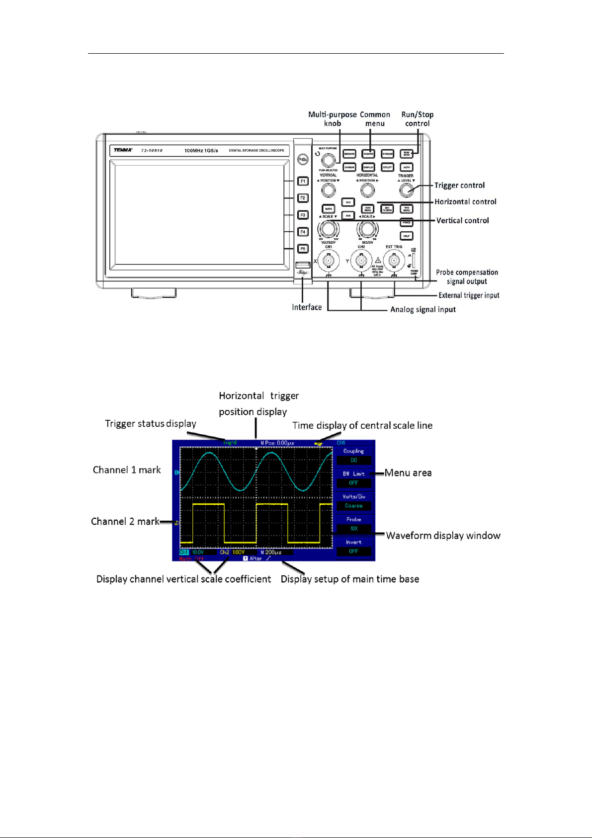
1.GettoKnowtheUserInterface
2.GeneralInspections
3.FunctionalInspections
4.ProbeCompensation
5.AutomaticSettingsofWaveformDisplay

Model72‐7610/72‐10510UserManual
4
6.IntroductiontotheVerticalSystem
7.IntroductiontotheHorizontalSystem
8.IntroductiontotheTriggerSystem
1. GettoKnowtheUserInterface
Gettingtounderstanddifferentpartsoftheuserinterfaceisoneofthemostimportant
taskstoknowtheoperations.Theoscilloscopeuserinterfaceconsistsof:
Verticalcontrol
Horizontalcontrol
Triggercontrol
LCDdisplayarea
Functionbuttons(F1,F2,F3,F4,F5)
Usermenuarea
Inputterminal(CH1,CH2,EXTTRIG)
Multi‐purposeknob
USBinterface
PleasegetfamiliarwiththeuserinterfacesshowninFigure1‐1andFigure1‐2.
Figure1‐1:72‐7610PanelDiagram‐5.7‐inchTFTcolorLCDdisplay

Model72‐7610/72‐10510UserManual
5
Figure1‐2:72‐10510PanelDiagram‐7‐inchTFTcolorLCDdisplay
Figure1‐3:UserInterfaceMenuDisplay(taking72‐10510asanexample)
2.GeneralInspections
Itisrecommendedtoinspecttheoscilloscopeaccordingtothefollowingsteps.
1.Inspectwhethertherearedamagescausedbytransportation
Incaseofbadlydamagestopackingboxorfoamedplasticmat,youshouldreplace
immediately.
2.Accessoriesinspection

Model72‐7610/72‐10510UserManual
6
Forprovidedaccessoriesdetails,descriptionhasbeenmadein“Accessories”sectionof
thisusermanual.Ifyoufindanyaccessoryismissingordamaged,pleasecontactTenma
distributorsorthelocaloffices.
3.Checkthemaininstrument
Incaseofdamagestotheappearanceofinstrument,abnormaloperationorfailureto
passtheperformancetests,pleasecontactTenmadistributorsorthelocaloffices.
Iftheinstrumentisdamagedduetotransportation,pleasepayattentiontokeepingthe
package,notifythetransportationdepartmentandTenma.Theywillmakearrangement
forrepairorreplacement.
3.FunctionInspections
Conductafastfunctionalinspectiontoverifywhethertheoscilloscoperunsnormally.
Pleasetakethefollowingsteps:
Powerontheoscilloscope
UserscanpowerontheoscilloscopewithvoltagesupplyofAC100V–AC240Vand
frequencyof45Hz–440Hz.Afterpoweringon,inordertoactivatethebestworking
status,pressUTILITYmenuafterwaiting30minutes,thenpressF1forself‐calibration.
Onthenextmenuinterface,pressF1buttonagainfor“factorysettings”asshownin
Figure1‐4.
Figure1‐4
Warning:pleaseconfirmthattheoscilloscopehasbeensafelygroundedtoavoidhazard.
Oscilloscopeaccessingtosignal
1) Theoscilloscopehastwoinputchannelswithanadditionalexternaltriggerinput
channel.Pleasecheckthesignalaccordingtothefollowingsteps.Connectaprobe
toCH1inputterminalandsettheattenuationrateswitchontheprobeas10×
(Figure1‐5)

Model72‐7610/72‐10510UserManual
7
Figure1‐5SettingofProbeAttenuationRateSwitch
2) Itisrequiredtosetprobeattenuationcoefficientontheoscilloscope.
Attenuationcoefficientchangestheverticalrangerateofinstrument,thusmakingthe
measurementresultcorrectlyreflecttheamplitudeofmeasuredsignals.Probe
attenuationcoefficientsaresetinthefollowingways:pressF4tomakethemenu
display10×.
Figure1‐6SettingofAttenuationCoefficientontheoscilloscope
3) Connecttheprobepinandgroundclamptothecorrespondingterminaloftheprobe
compensationsignal.PressAUTOkey.Withinseveralseconds,squarewavedisplay
(1kHz,about3V,peak‐to‐peakvalue)isasshowninFigure1‐7.CheckCH2inthesame
way;pressOFFfunctionkeytocloseCH1;pressCH2functionkeytoturnonCH2;repeat
step2and3.

Model72‐7610/72‐10510UserManual
8
Figure1‐7ProbeCompensationSignal
4.ProbeCompensation
Whenconnectingtheprobewithanyinputchannelforthefirsttime,itisrequiredto
maketheadjustment,matchingtheprobewiththeinputchannel.Probewithoutbeing
compensatedandcalibratedwillcausemeasurementerrorormistake.Toadjustprobe
compensation,followthestepsbelow:
1. Settheprobemenuattenuationcoefficientas10×,placetheswitchontheprobeat
10×andconnecttheoscilloscopeprobewithCH1.Connecttheprobeendtothe
signaloutputconnectoroftheprobecompensator,andconnectthegroundclamp
tothegroundleadconnectorofprobecompensator.TurnonCH1andpressAUTO.
2.Observedisplayedwaveform
Figure1‐8aProbeCompensationandCorrection
Ifthescreendisplays“under‐compensation”or“over‐compensation”forwaveformas
showninabovefigures,usescrewdriverwithnonmetalhandletoadjustthevariable
capacitanceontheprobeuntilscreendisplays“correctcompensation”forwaveformas
showninthebelowfigure.
Over‐compensationCorrectcompensationUnder‐compensation

Model72‐7610/72‐10510UserManual
9
Warning:Toavoidelectricalshockwhenmeasuringhighvoltage
withprobe,pleaseensurethattheinsulationleadoftheprobeisin
goodconditionanddonotcontactthemetalpartoftheprobe
whenconnectingtopowersupply.
5. AutomaticSettingofWaveformDisplay
Theoscilloscopehasautomaticsettingfunction.Accordingtoinputsignals,
automaticallyadjusttheverticaldeflectionfactor,scanningtimebaseandtriggermode
untilthemostappropriatewaveformisdisplayed.Inautomaticsetting,thefrequencyof
themeasuredsignalisrequiredtobe≥50Hzandthedutyratiois>1%.
Applyautomaticsetting
1.Connectmeasuredsignaltosignalinputchannel.
2.PressAUTOkey.Theoscilloscopewillautomaticallysetitsverticaldeflectionfactor,
scanningtimebaseandtriggermode.Iffurthercarefulobservationisrequired,adjustment
canbeconductedagainafterautomaticsettinguntilthewaveformdisplayreachesrequired
optimumeffect.
6.IntroductiontotheVerticalSystem
Asshowninthefigureonnextpage,thereareaseriesofkeysandknobsinthevertical
controlarea.Practicesbelowwillgraduallyguideyoutogetfamiliarwiththecontrolling
oftheverticalsystem.
Figure1‐8b:Correctcompensation

Model72‐7610/72‐10510UserManual
10
Figure1‐9VerticalControlAreaonthePanel
Model72‐7610(Left)Model72‐10510(Right)
1. Usetheverticalpositionknobtomovetheverticalpositionofthewaveformdisplay
ontheLCDscreen.Bydefault,waveformsshouldbedisplayedatthecenterofthe
screen.
2. Usersshouldseethewaveformwillmoveverticallyupwardanddownwardwhen
theknobisrotated.
3. Userscanalsochangethewaveformscalebyrotatingthescaleknobonthevertical
system.Pleasenoticethatthe“V/div”willbechangedtoindicatethecorresponding
verticalscalelevel.
4. Userscanenable/disabletheinputchannelbypressingthe[CH1]and[CH2]button
ontheverticalsystem.(For72‐10510)
Attention:
Todisabletheinputchannelfor72‐7610,pleasepress[OFF]buttononthevertical
system.
Moreverticalsystemsettingwillbeexplainedin“Operations”sectionofthisusermanual.
7.IntroductiontotheHorizontalSystem
Asshowninthefigureonnextpage,thereisonekeyandtwoknobswithinthe
horizontalcontrolarea.Practicesbelowwillgraduallyguideyoutogetfamiliarwiththe
horizontaltimebasesetting.

Model72‐7610/72‐10510UserManual
11
Figure1‐10HorizontalControlAreaonthePanel
72‐7610(Left)72‐10510(Right)
1.UsehorizontalSCALEknobtochangehorizontaltimebasescalesettingsandobserve
thestateinformationchanges.TurnhorizontalSCALEknobtochange“s/div”timebase
scale,andyoucanfindcorrespondingchangesinthetimebasescaledisplayof
correspondingchannelinthestatusbar.
Horizontalscanningratestepsupinthemultiplesof1,2and5
e.g.1ms/div‐>2ms/div‐>5ms/div‐>10ms/div….etc.
Note:thehorizontaltimebaserangeof72‐7610/72‐10510variesbetween2ns/divand
50s/div.Detailsarelistedintechnicalspecifications.
2.UsehorizontalPOSITIONknobtoadjustthesignalhorizontalpositioninthewaveform
window.HorizontalPOSITIONknobcontrolsthesignaltriggershift.Whenappliedto
triggershift,thewaveformhorizontalmovementcanbeobservedalongwithPOSITION
knobturning.
Morehorizontalsystemsettingwillbeexplainedin“Operations”sectionofthisusermanual.
8.IntroductiontotheTriggerSystem
AsshowninFigure1‐11,oneknobandthree(ortwo)keysareinthetriggermenu
controlarea.Practicesbelowwillgraduallyguideyoutobefamiliarwiththetrigger
systemsetting.

Model72‐7610/72‐10510UserManual
12
Figure1‐11TriggerMenuonthePanel
72‐7610(Left)72‐10510(Middle)TriggerMenuDisplay(Right)
Moretriggersystemsettingswillbeexplainedin“Operations”sectionofthisusermanual.
Ⅴ.Specifications
Unlessotherwisespecified,alltechnicalspecificationsareapplicabletotheprobeswith
attenuationswitchsetas10×andtotheoscilloscope.Theoscilloscopemustfirstmeet
thefollowingtwoconditionstosatisfythosespecificationstandards:
Theoscilloscopemustcontinuouslyrunforoverhalfanhourintheoperating
temperatureenvironment.
A. TechnicalSpecifications
SamplingSystemSpecifications
SamplingrateReal‐timeEquivalent
Sampling
rate
72‐76101GS/s50GS/s
72‐1051025MS/s
AverageNcanbechosenamong2,4,8,16,32,64,128and256;Nisthenumberof
averagesamples.
Note:Therealtimesamplingrateof72‐7610is250MS/s,withoutequivalentsampling.
InputChannel
Specifications
Inputcoupling DC,ACandGND
Inputimpedance 72‐76101±2%MΩwith21±3pF
72‐105101±2%MΩwith24±3pF
Probeattenuation
coefficient 1×,10×,100×,1000×

Model72‐7610/72‐10510UserManual
13
Maximuminput
voltage 400V(DC+ACpeakvalue,1MΩinputimpedance)
Timedelaybetween
Channels(Typical) 150ps
HorizontalSystemSpecifications
Waveform
interpolation Sin(x)/x
Horizontalresolution25pixels/div
Recordlength 2×512ksamplingpoint
Storagedepth 25k
Scanningscope
72‐76102ns/div‐50s/div
72‐105102ns/div‐50s/div
Samplingrateand
delaytimeaccuracy ±50ppm(anyinterval≥1m)
Measurement
accuracyoftime
interval(△T)(full
bandwidth)
Singletime:±(1sampling
interval+50ppm×reading+0.6ns)
>16averagevalues:±(sampling
interval+50ppm×reading+0.4ns)
VerticalSystemSpecifications
Analog‐to‐digital
converter(A/D)
8‐bitresolution,samplingattwochannelsatthesame
time
Deflectioncoefficient
(V/div)range
(atinputBNC)
72‐76102mV/div‐5V/div
72‐105101mV/div‐20V/div
Verticalrange ±10div(72‐7610is±5div)
Selectablebandwidth
limitation(Typical) 20MHz
Lowfrequency
response(ACcoupling,
‐3dB)
≤10Hz(atBNC)
DCgainaccuracy
(samplingoraverage
samplingmode)
72‐7610:
±4%(Whenverticalsensitivityis2mV/divor5mV/div)
±3%(Whenverticalsensitivityis10mV/div‐5V/div)

Model72‐7610/72‐10510UserManual
14
72‐10510:
±5%(Whenverticalsensitivityis1mV/divor2mV/div)
±4%(Whenverticalsensitivityis5mV/div)
±3%(Whenverticalsensitivityis10mV/div‐20mV/div)
DCmeasurement
accuracy
(averagesampling
mode)
72‐7610:
Whenverticalpositionis0andN≥16:
±(4%×reading+0.1div+1mV)at2mV/divand
5mV/div;
±(3%×reading+0.1div+1mV)from10mV/divto
5V/div;
Whenverticalpositionisnotat0andN≥16:
±[3%×(reading+verticalpositionreading)+
(1%×verticalpositionreading)]+0.2div)
from2mV/divto200mV/div+2mV
Thesettingvaluefrom200mV/divto5V/divplus50mV
72‐10510:
Whenverticalpositionis0andN≥16:
±(5%×reading+0.1div+1mV)andselects1mV/divor
2mV/div;
±(4%×reading+0.1div+1mV)andselects5mV/div;
±(3%×reading+0.1div+1mV)andselects10mV/divor
20mV/div;
Whenverticalpositionis0andN≥16:
±(3%×(reading+verticalpositionreading)+
(1%×verticalpositionreading)]+0.2div)
Thesettingfrom5mV/divto200mV/divplus2mV;the
settingvaluefrom200mV/divto20V/divplus50mV
Measurement
accuracyofvoltage
difference(△V)
(averagesampling
mode)
Underthesamesettingandenvironmentconditions
andafteraveragingthecapturedwaveformswitha
quantityof≥16,thevoltagedifference(ΔV)between
anytwopointsonthewaveform:±
(3%×reading+0.05div)
Note:Therangeofdeflectionfactorfor72‐10510is2mV/div‐10V/div(intheplaceofinput
BNC).

Model72‐7610/72‐10510UserManual
15
BandwidthforEachModel
Model Analog
Bandwidth
Real‐Time
Bandwidth RiseTime
72‐7610150MHz100MHz2.3ns
72‐1051025MHz25MHz14ns
TriggerSystemSpecifications
Triggersensitivity ≤1div
Rangeoftriggerlevel Interior Fromthescreencenter
±5div
EXT±3V
EXT/5*±15V
Triggerlevelaccuracy
(Typical)applicablefor
thesignalwithrisingand
fallingtime≥20ns
Interior ±(0.3div×V/div)
(within±4divfromthe
screencenter)
EXT) ±(6%settingvalue+40mV)
EXT/5*±(6%settingvalue
+200mV)
Pre‐triggercapacityNormalmode/scanmode,pre‐trigger/delaytrigger,
thepre‐triggerdepthadjustable
Hold‐offrange72‐7610100ns‐1.5s
72‐1051080ns‐1.5s
Setthelevelto50%
(Typical).
Operateundertheconditionofinputsignal
frequencyof≥50Hz
EdgeTrigger
Edgetype Rise,fall,riseandfall
PulseWidthTrigger
Triggermode (>,<,and=)positivepulsewidthand(>,<,and=)
negativepulsewidthrange
Pulsewidthrange 20ns‐10s
VideoTrigger*
Triggersensitivity(videotrigger,
Typical)
Interior 2divVpp
EXT) 400mV
EXT/5*2V
Signalmodelandline/field
frequency(videotriggertype)
SupportstandardNTSCandPAL,andtheline
rangesarerespectively1‐525(NTSC)and
1‐625(PAL).

Model72‐7610/72‐10510UserManual
16
AlternatingTrigger
CH1trigger Edge,pulsewidth,andvideo
CH2trigger Edge,pulsewidth,andvideo
Note:NoEXT/5functionfor72‐10510.
Measurements
Cursor
CursorParameters
Voltagedifferencebetween
cursors(△V),
Timedifferencebetween
cursors(△T),
Reciprocalof△T(Hz)(1/△T)
Track Voltagevalueandtimevalueof
pointofwaveform
Automatic
measurement
Vpp,Vamp,Vmax,Vmin,Vtop,Vbase,Vmid,Average,Vrms,
Overshoot,Preshoot,Frequency,Period,RiseTime,Fall
Time,+Width,‐Width,+Duty,‐Duty,Delay
Mathoperation +,‐,×,÷
Store(waveform
andsetting) 20groupsofwaveforms,and20kindsofsettings
FFTWindow Hanning,Hamming,Blackman,
Rectangle
Samplingsize 1024points
Lissajousfigure Phasedifference ±3degrees
Triggerfrequency
meter(72‐10510only)
Readingresolution 6bits
Triggersensitivity ≤30Vrms
Accuracy(typical) ±51ppm(+1character)
B. GeneralTechnicalSpecifications
Display
72‐761072‐10510
Displaytypes 5.7‐inchLCD 7‐inchLCD
Displayresolution 320horizontal×240
verticalpixels(RGB)
400horizontaB×240
verticalpixels(RGB)
Displaycolor Color
WaveformluminanceAdjustable(color)(72‐10510only)
Backlightintensity
(typical) 300nit

Model72‐7610/72‐10510UserManual
17
ProbeCompensatorOutput
Outputvoltage(Typical) About3Vpp,whentheload≥1MΩ
Frequency(Typical) 1kHz
InterfaceFunction
Standardconfiguration 72‐76101USBdevice;1USBHost
72‐105101USBOTG
Optionalcomponent LANcommunicationportfor72‐7610
PowerSource
Powervoltage 100‐240VACRMS,45‐440HzCATII
Powerconsumption Lessthan30VA
Fuse F1.6AL250V(Fuseisinsidetheinstrument
housing)
EnvironmentSpecifications
TemperatureRangeOperatingTemperatureRange:0Ԩ~+40Ԩ
StorageTemperatureRange:‐20Ԩ‐+60
CoolingBuild‐incoolingfan
OperatingHumidityRange
<35Ԩ:≤90%RH
35Ԩ‐40Ԩ:≤60%RH
OperatingAltitudeBelow3,000m
MechanicalSpecifications
72‐761072‐10510
Size W 320mm306mm
H 150mm147mm
D 130mm122mm
Weight Excludingpackage 2.5kg2.2kg
Includingpackage 4.0kg3.3kg
IPProtection
IP2x
CalibrationInterval
Therecommendedcalibrationintervalisoneyear.

Model72‐7610/72‐10510UserManual
18
Ⅵ.Operations
Untilnow,youhavehadbasicunderstandingaboutthevertical,horizontal,andtrigger
systemcontrolsoftheoscilloscope.Werecommendyoutore‐readthe“Functions”
sectionifyouarestillnotfamiliarwiththebasicoperationcontrols.
Inthissection,youwilllearndifferentsettingsrelatedtotheoscilloscope:
1. SettheVerticalSystem
(CH1,CH2,MATH,REF,OFF)
2. SettheHorizontalSystem
(MENUorHORIMENU)
3. SettheTriggerSystem
(MENU,TRIGMENU,50%andFORCE)
4. SettheAcquireSystem(ACQUIRE)
5. SettheDisplaySystem(DISPLAY)
6. SettheStorageandLoadSystem(STORAGE)
7. SettheUtilitySystem(UTILITY)
8. SettheMeasurementParameters(MEASURE)
9. SettheCursorMeasurement(CURSOR)
10. SystemMessageExamplesandTroubleshooting
Itissuggestedtoreadthissectioncarefullytounderstandmultiplemeasuringfunctionsand
systemoperationmethodsoftheoscilloscope.
1. SettheVerticalSystem
Eachchannelfortheoscilloscopecanbesetindependentlyontheverticalsystemmenu.
AfterpressingCH1orCH2functionkey,thesystemshalldisplayfunctionmenuofCH1or
CH2channel.SeeTable2‐1belowfordescription.
Table2‐1
This manual suits for next models
1
Table of contents
Other Tenma Test Equipment manuals

Tenma
Tenma 72-2650 User manual

Tenma
Tenma 72-2665 User manual

Tenma
Tenma 72-2650 User manual

Tenma
Tenma 72-7985 User manual

Tenma
Tenma 72-9355 User manual

Tenma
Tenma 72-10175 User manual

Tenma
Tenma DSO Series User manual

Tenma
Tenma 72-9405 User manual

Tenma
Tenma 72-9966 User manual

Tenma
Tenma 72-7630 User manual

Tenma
Tenma 72-8710 User manual

Tenma
Tenma 72-3565 User manual

Tenma
Tenma 72-3575 User manual

Tenma
Tenma 72-6802 User manual

Tenma
Tenma 72-490 User manual

Tenma
Tenma 72-9400A User manual

Tenma
Tenma 72-2680 User manual

Tenma
Tenma 72-7615 User manual

Tenma
Tenma 72-14520 User manual

Tenma
Tenma 72-6947 User manual