Teletronics International TBC-800 User manual
TBC-
Bandwidth Controller
800
Version 1.0.2
Copyright 2006 Teletronics International, Inc.
2 Choke Cherry Road
Rockville, MD 20850
1

Table of Contents
Overview and Features ………………….………..…………………………… 3
Structure of Bandwidth Control …………….…………………………………4
Installation ……………………………………………………………………… 4
Network Installation Diagram …................…………………………………….5
Web Configuration Interface ………………………………………………….. 6
Login ………………………………………………………………..…… 6
System Overview ………………………………………………...……… 6
Network Settings ………………………………………………..………. 7
Administration …………………………………………………..………. 9
Services ………………………………………………………..………. 13
Bandwidth Control ……………………..……………………………… 14
Status …………………………………..………………………………. 18
Save & Reboot ………………………..……………………………….. 20
Console / COM Port Configuration …………………………...…………….. 21
Configuration Examples ……………………………………………………… 24
Product Specifications ………………………………………………………... 25
RMA Guidelines ………………………………………………………………. 27
2

Overview and Features
TBC (Teletronics Bandwidth Controller) is a low-cost, versatile and easy to operate
device specifically designed for network service providers or enterprise customers to
provide a consistent bandwidth flow to the end stations. TBC system automatically shape
TCP/UDP traffic based on built-in rules.
TBC system is simple and reliable allowing network operators to quickly and easily bring
network traffic into balance without changing the existing network infrastructure.
Scalable:
•Create and manage up to 64 Groups
•Each group can have up to 256 Leaf Class/Sessions
Bandwidth Shape:
•Limit Upload/Download speed for every group and leaf class
•Shape Bandwidth by IP address, Subnet, Group, Mac Address and Port
•Ability to apply single or multi-filters for each class
•Prioritize and reserve bandwidth for certain traffic like VoIP and Webcast
Manageable:
•Web Based Management Tool
•Varies Interface: HTTP/HTTPS/Telnet/Serial Console Port
•Compact or Detail Syslog
Network Function:
•DHCP Server
•SNMP
•Remote Syslog
•Utilities: Ping, Trace Route, Tcpdump, NetPerf
Security:
•Admin Configuration with Password
•Restriction access by IP address filtering
•VPN (IPSec/PPTP) pass through
Mounting:
•Desktop
•Wall Mount
•Rack Mount (available later this year)
3
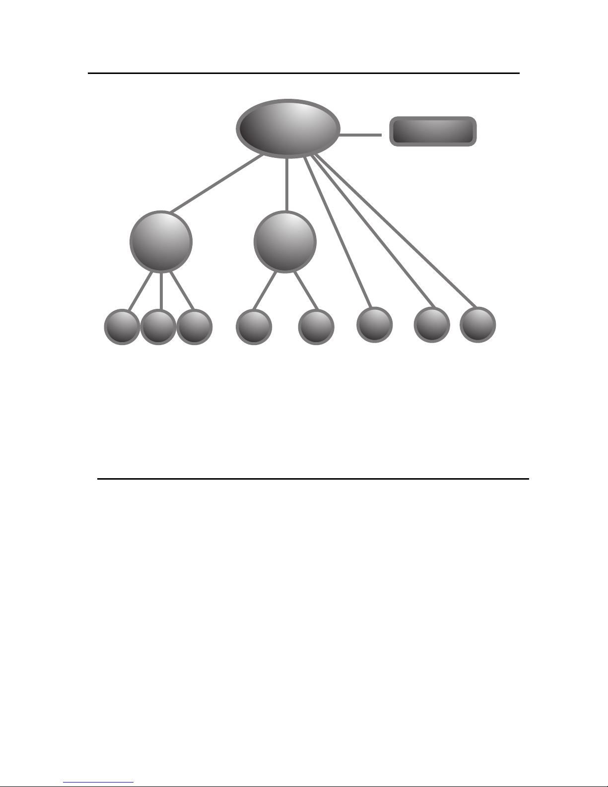
LEAF
CLASS
USING ROOT CONFIGURATION PAGE TO SETUP ROOT CLASS AND DEFAULT RATE.
USING PRIMARY GROUP PAGE TO DEFINE GROUP CLASS.
USING QoS SETTING PAGE TO DEFINE LEAF CLASS.
LEAF
CLASS
LEAF
CLASS
LEAF
CLASS
LEAF
CLASS
DEFAULT RATE
LEAF
CLASS
GROUP
CLASS 2
ROOT CLASS
GROUP
CLASS 1
LEAF
CLASS
LEAF
CLASS
Structure of Bandwidth Control
Figure 1
Installation
TBC should be installed between end users and router/ gateway to optimize the
performance and efficiency. This product is a hardware version, so it can be installed on
any traffic you would like to shape. Because TBC is in Bridge Mode, it can shape
bandwidth between different Subnet/IP as well.
TBC has one WAN port, and three LAN port. WAN interface should connect to
router/gateway of DSL, T1, or any internet connection. LAN interface should be
connecting to internal network directly or through a switch/hub.
Steps:
Set your computer's IP Address to 192.168.1.100 with Subnet Mask: 255.255.255.0 (or
any available IP address in the 192.168.1.x subnet). Use a crossover cable to connect the
LAN1 port to your computer's Ethernet port. Connect power adapter to TBC-800.
For more information about configuration and operation, please see Web Configuration
Interface section. Please see the next page for Installation Diagram (Figure 2).
4
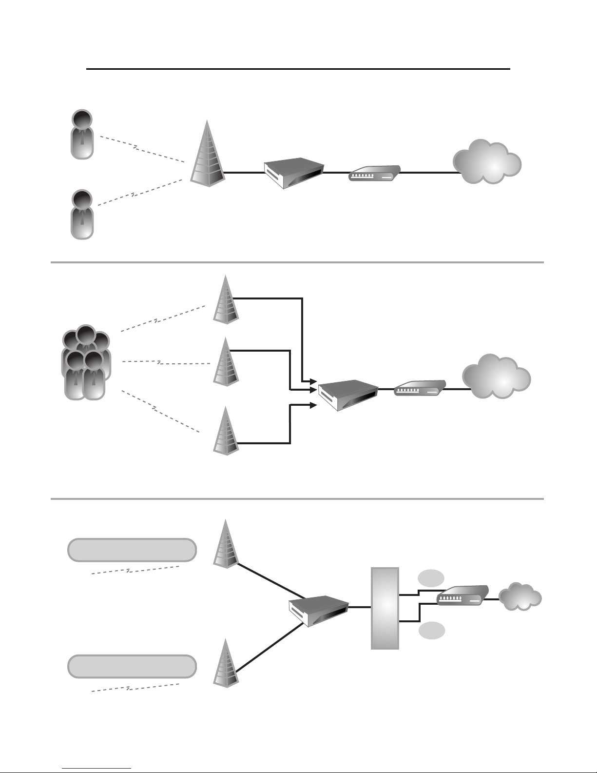
CLIENT #1
BASE STATION
BASE #1
BASE #2 (PLEASE NOTE: IF MORE THAN 3 BASE STATIONS,
YOU WOULD NEED TO ADD A HUB IN BETWEEN)
TBC ROUTER INTERNET
CLIENT #2
CLIENTS TBC
TBC
SUBNET #1
SUBNET #2
ROUTER INTERNET
INTERNET
ROUTER
SCENARIO 1
SHAPING BASE ON IP
SCENARIO 2
SCENARIO 3
192.168.1.X
192.168.10.X
H
U
BSUB2
SUB1
Figure 2
Network Installation Diagram
5

Web Configuration Interface
Login
Default IP Address: 192.168.1.124
To access the web control interface, open up a web browser and type in the factory
default IP address in the URL.
Then press Enter on your keyboard, you will see the login prompt window appear.
Default User Name: admin
Default Password: admin
Enter User name and password, and click OK.
Note: You may set a new password by clicking the Administration-Password tab after you
successfully login to the web page.
System Overview
This is the main web interface home page. It displays Firmware Version and IP
properties.
6
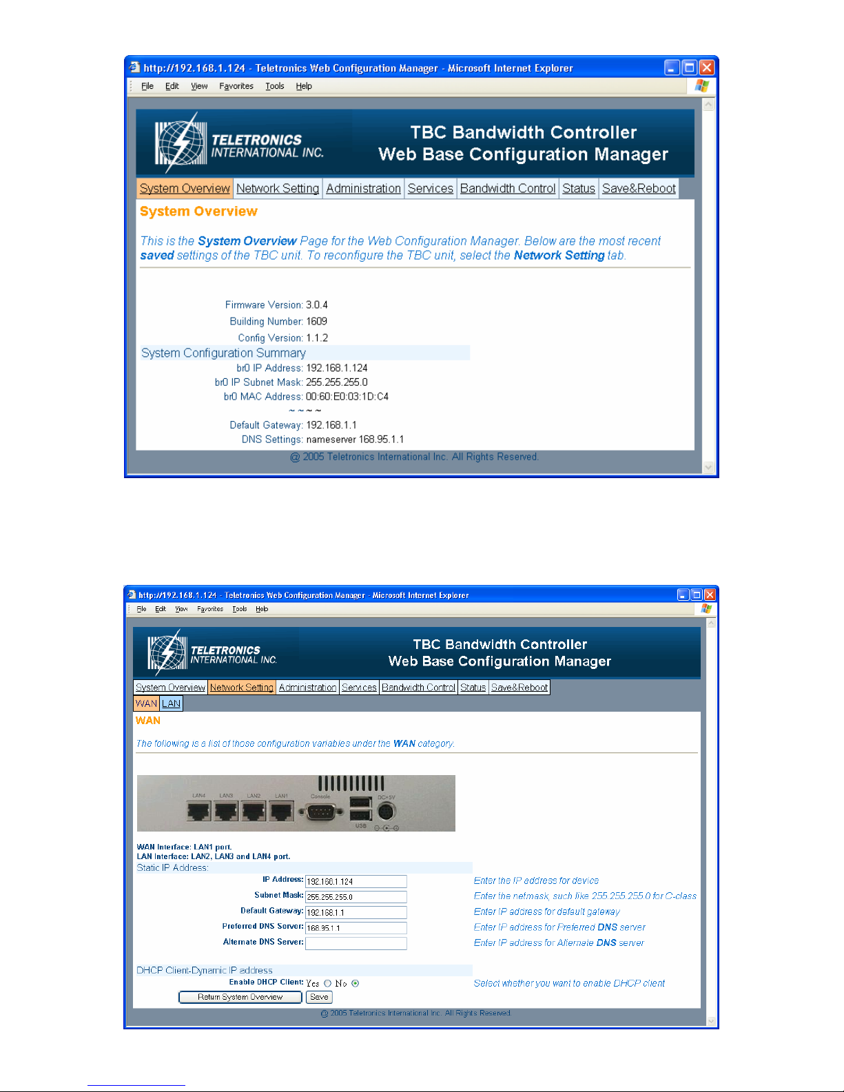
Network Setting
- WAN
7
Static IP Address:
Manually setup an IP for this device
•IP Address
•Subnet Mask
•Default Gateway
•Preferred DNS Server
•Alternate DNS Server
DHCP Client:
Set up the device as a DHCP client which will pick up an IP from a DHCP server
Click Save to store the setting
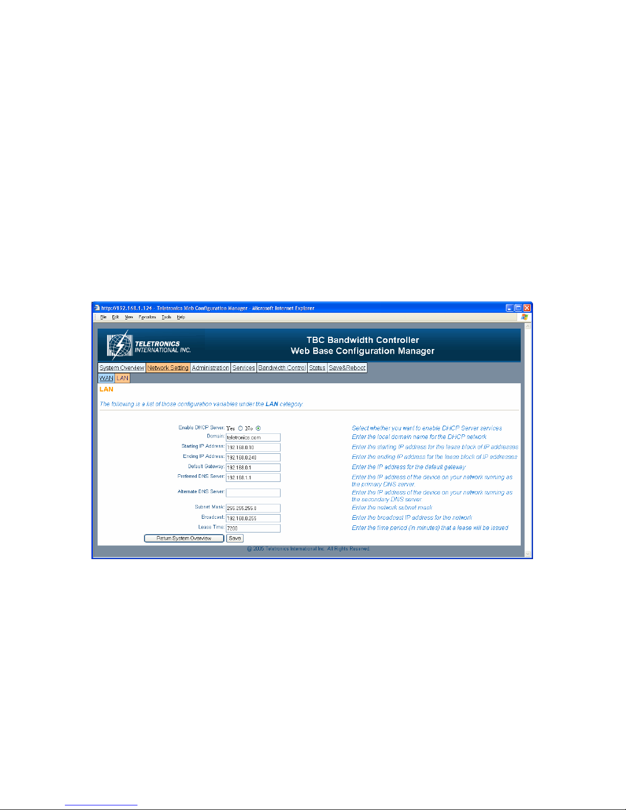
- LAN
TBC can be setup as a DHCP server for the LAN network.
Enable DHCP Server:
•Enable DHCP Server: select Yes
•Domain: Enter the name of the LAN network domain
•Starting & Ending IP Address: Enter the starting and the ending IP address
dynamically assigning to DHCP clients.
•Default Gateway: Enter the LAN network gateway IP address
•Preferred & Alternate DNS Server: Enter the preferred & alternate Domain Name
Server’s IP address
•Subnet Mask: Enter the LAN network subnet
8
•Broadcast: Enter the LAN network Broadcast IP address
•Lease Time: Enter the time period (in minute) that a lease will be issued
Click Save to store the setting
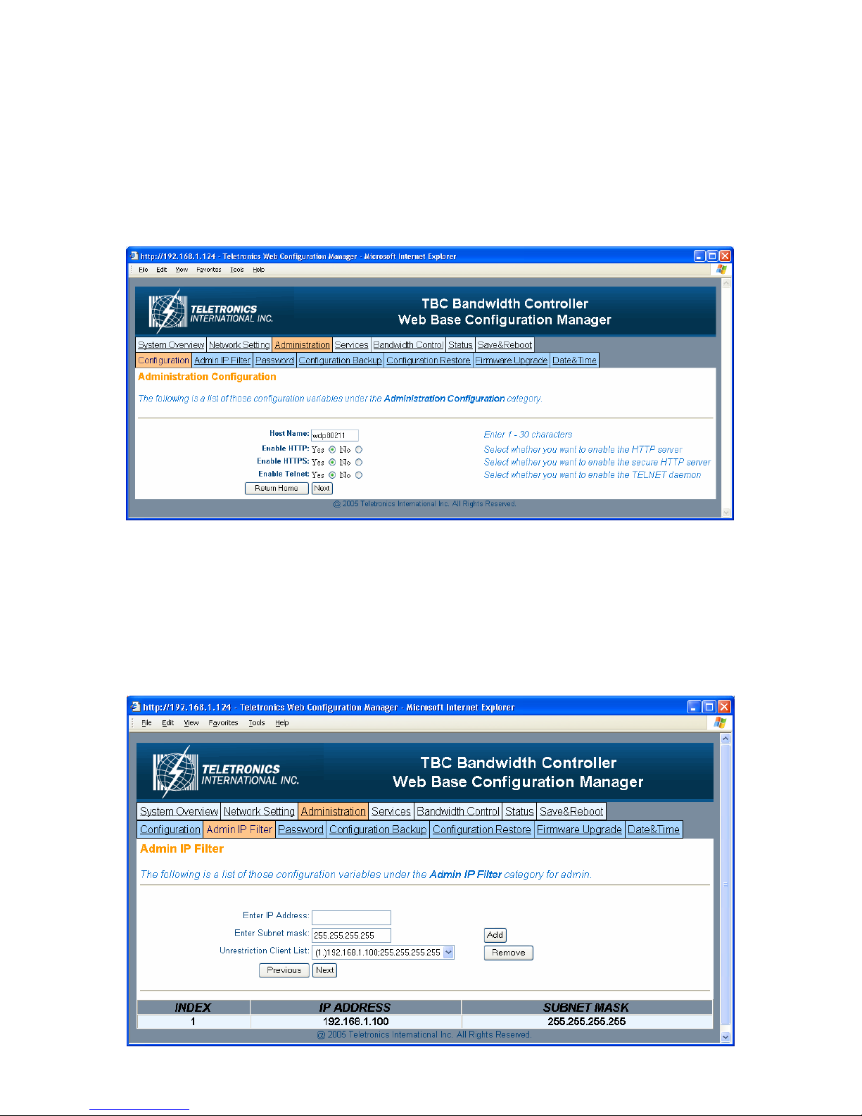
Administration
- Configuration
•Host Name: This is the name for this device. Host name can help to identify the
location if there is more then one bandwidth controller in the LAN network.
•Enable HTTP: HTTP is enable by default
•Enable HTTPS: HTTPS is enable by default
•Enable Telnet: Telnet is enable by default
- Admin IP Filter
9
•Enter IP Address: Enter IP address that will have permission to access this device
•Enter Subnet Mask: Enter Subnet Mask to grant permission to a whole or part of
subnet. For example: if enter IP: 192.168.1.100 & subnet: 255.255.255.0, any
address at 192.168.1.x network can access this device.
Click Add or Remove to modify the Admin IP access list.
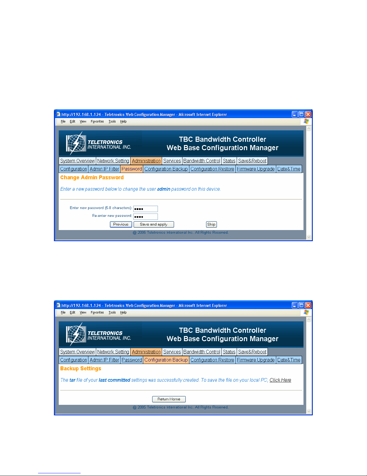
- Password
You can reset password for user admin. You must enter the same password twice for
confirmation. Click Next to Save, then click Commit Changes to permanently apply the
change.
- Configuration Backup
10
Table of contents
Popular Controllers manuals by other brands

Digiplex
Digiplex DGP-848 Programming guide

YASKAWA
YASKAWA SGM series user manual

Sinope
Sinope Calypso RM3500ZB installation guide

Isimet
Isimet DLA Series Style 2 Installation, Operations, Start-up and Maintenance Instructions

LSIS
LSIS sv-ip5a user manual

Rockwell Automation
Rockwell Automation 1769-L31 installation instructions


