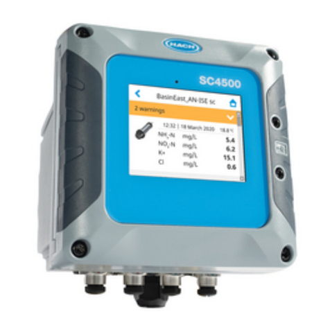
Hach SC4500 User manual

DOC343.52.90752
PROFINET and EtherNet/IP
modules
11/2021, Edition 2
User manual


Table of Contents
Section 1 General information............................................................................ 3
1.1 Safety information................................................................................................. 3
1.2 Use of hazard information..................................................................................... 3
1.3 Product overview.................................................................................................. 3
Section 2 Commissioning checklist ...............................................................5
Section 3 Installation............................................................................................... 5
3.1 Install the module.................................................................................................. 5
3.2 Electrical installation............................................................................................. 7
Section 4 Startup....................................................................................................... 8
Section 5 Operation................................................................................................. 8
5.1 Configure the Ethernet ports................................................................................. 8
5.2 Install the configuration file................................................................................... 9
5.2.1 Install the PROFINET GSDML file.............................................................. 9
5.2.2 Install the EtherNet/IP EDS file................................................................. 10
5.3 Configure the PLC environment......................................................................... 11
5.3.1 Configure the PROFINET environment.................................................... 11
5.3.2 Configure the EtherNet/IP environment.................................................... 17
5.4 Configure the module......................................................................................... 27
5.4.1 Configure the PROFINET module ........................................................... 27
5.4.2 Configure the EtherNet/IP module ........................................................... 31
5.4.2.1 Configure the EtherNet/IP data structure....................................... 36
Section 6 PROFINET Telegram composition.............................................. 38
Section 7 EtherNet/IP Telegram composition............................................ 40
Section 8 LED status, diagnostic and messages..................................... 41
Section 9 Replacement parts and accessories......................................... 43
1

Table of Contents
2

Section 1 General information
In no event will the manufacturer be liable for direct, indirect, special, incidental or consequential
damages resulting from any defect or omission in this manual. The manufacturer reserves the right to
make changes in this manual and the products it describes at any time, without notice or obligation.
Revised editions are found on the manufacturer’s website.
1.1 Safety information
The manufacturer is not responsible for any damages due to misapplication or misuse of this product
including, without limitation, direct, incidental and consequential damages, and disclaims such
damages to the full extent permitted under applicable law. The user is soley responsible to identify
critical application risks and install appropriate mechanisms to protect processes during a possible
equipment malfunction.
Please read this entire manual before unpacking, setting up or operating this equipment. Pay
attention to all danger and caution statements. Failure to do so could result in serious injury to the
operator or damage to the equipment.
Make sure that the protection provided by this equipment is not impaired. Do not use or install this
equipment in any manner other than that specified in this manual.
1.2 Use of hazard information
D A N G E R
Indicates a potentially or imminently hazardous situation which, if not avoided, will result in death or
serious injury.
WARNING
Indicates a potentially or imminently hazardous situation which, if not avoided, could result in death
or serious injury.
CAUTION
Indicates a potentially hazardous situation that may result in minor or moderate injury.
N O T I C E
Indicates a situation which, if not avoided, may cause damage to the instrument. Information that
requires special emphasis.
1.3 Product overview
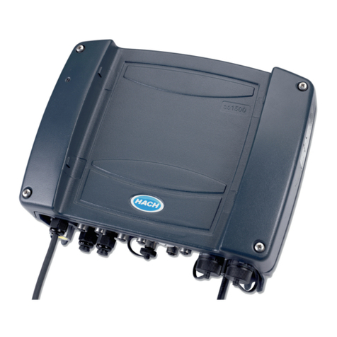
The SC4500 controller is available with optional expansion modules:
• EtherNet/IP module—The controller can connect to a PLC through Industrial Ethernet Protocol
including a EtherNet/IP solution. Line, Star and Ring topologies are available.
• PROFINET module—The controller can connect to a PLC through the Industrial Ethernet Protocol,
which includes a PROFINET solution. Line, Star and Ring topologies are available.
The SC4500 controller PROFINET and EtherNet/IP modules are applicable to the network topologies
that follow:
• Line (chain) topology—Connects the devices with integrated switches in the field. Refer to
Figure 1.
• Star topology—Devices connects to a central switch. Refer to Figure 2.
• Ring topology—The network is closed in a ring shape to get redundancy. The media redundancy
protocol (MRP) is used for PROFINET and device level ring (DLR) for EtherNet/IP. Refer to
Figure 3.
English 3

Figure 1 Chain topology
Figure 2 Star topology
Figure 3 Ring topology
4 English

Section 2 Commissioning checklist
Use the checklist that follows to complete the PROFINET or EtherNet/IP installation and
configuration procedure. Do the tasks in the order given.
Task Completed
Install the module on page 5 in the controller.
Electrical installation on page 7—Make all of the necessary hardware connection
(wiring).
Configure the Ethernet ports on page 8 on the controller
Install the configuration file on page 9 on the PLC environment.
• PROFINET—GSDML file
• EtherNet/IP—ESD file
Configure the PLC environment on page 11
Configure the module on page 27 (PROFINET or EtherNet/IP) on the controller.
Section 3 Installation
D A N G E R
Multiple hazards. Only qualified personnel must conduct the tasks described in this
section of the document.
3.1 Install the module
D A N G E R
Electrocution hazard. Always remove power to the instrument before making electrical
connections.
Make sure that the PROFINET or EtherNet/IP module is installed in the controller. Refer to the
documentation supplied with the module1.
Notes:
• Make sure that the controller is compatible with the module. Contact technical support.
• Connect the module to the third slot on the right side of controller. Refer to Figure 4.
1The module is factory installed based on the controller configuration.
English 5

Figure 4 EtherNet/IP or PROFINET module slot
1 Module slot
Configure the controller with 1 or 2 Industrial Ethernet ports based on the network configuration. For
star topologies, configure the controllers with 1 Ethernet port. Refer to Figure 5. For chain or ring
topologies, configure the controller with 2 Ethernet ports. Refer to Figure 6.
Figure 5 Controller with 1 Ethernet port—LAN + PROFINET or Ethernet/IP
6 English

Figure 6 Controller with 2 Ethernet ports—PROFINET or EtherNet/IP only
3.2 Electrical installation
D A N G E R
Explosion hazard. Do not connect or disconnect electrical components or circuits to the
equipment unless power has been removed or the area is known to be non-hazardous.
Items to collect:
• SC4500 controller with PROFINET or EtherNet/IP module installed
• PLC
• PROFINET/Ethernet switch (optional, only for star topologies)
• LAPTOP with TIA or PLC environment installed
• PROFINET/Ethernet copper cable
Use a Ethernet copper cable for the connection. The cable is a 4-wire shielded, green-colored cable
that gives 100 Mbps Fast Ethernet minimum at 100 meters maximum. The cables used in industrial
networks are CAT 5, 5E, CAT 6, 6A or CAT 7 category cables. The cables have an
IP66 M12 connector or IP20 RJ45 connector.
Hach supplies two standard cable accessories and a kit that includes the connectors to make a
custom cable. Refer to Replacement parts and accessories on page 43.
Make all of the electrical connections in the PROFINET or EtherNet/IP network. Refer to Figure 7.
1. Connect the SC4500 controller to the industrial switch (M12 - RJ45 cable).
2. Connect the PLC to the industrial switch (RJ45 - RJ45 cable).
3. Connect the Laptop to the industrial switch (RJ45 - RJ45 cable).
English 7

Figure 7 Wiring example
1 PLC 3 SC4500 controller
2 Industrial switch 4 Laptop
Section 4 Startup
1. Supply power to the controller and PLC.
2. Set the PLC to on.
Section 5 Operation
5.1 Configure the Ethernet ports
Make sure that the Ethernet port configuration in the controller is set to one of the IEP (industrial
Ethernet ports) options.
1. Push the main menu icon, then select Controller > Connectivity > LAN > Ethernet ports.
2. Select one of the options that follow based on the wiring configuration of the controller.
Option Description
IEP only The two Ethernet ports are configured for PROFINET or EtherNet/IP. Port 2 in the
module is enabled. Refer to Figure 6 on page 7.
MIX IEP One Ethernet port is configured for LAN connectivity and the other Ethernet port is
configured for PROFINET or EtherNet/IP. Port 2 in the module is disabled. Refer to
Figure 5 on page 6.
Note: When Mix IEP is selected, LAN port configuration shows in the LAN menu. LAN port
configuration setting is used only for LAN connectivity configuration, not for Industrial Ethernet
port configuration.
8 English

5.2 Install the configuration file
Download the configuration file from the manufacturer's website. Install the file on the PLC
environment.
Note: Make sure to remove the old configuration file before a new configuration file is installed.
5.2.1 Install the PROFINET GSDML file
An example of installation in TIA (Totally Integrated Automation) portal from SIEMENS PLC software
follows:
Note: Steps that follow is an example. Steps and commands may change based on the installed PLC solution.
1. Select Options > Manage general station description files
2. Search for the folder where the file was saved.
3. Select the file, then click Install.
When the file is installed, "SC4500 Controller 1 port" and "SC4500 Controller 2 port" are available in
the PLC hardware catalog view. Select OTHER FIELD DEVICES > PROFINET IO > IO > HACH
LANGE > HACH SC4500 CONTROLLERS folder.
English 9

5.2.2 Install the EtherNet/IP EDS file
An example of installation in Studio 5000 Logix Designer software from Rockwell Automation
Technologies Inc. follows:
Note: Steps that follow is an example. Steps and commands may change based on the installed PLC solution.
1. Select Tools > EDS hardware Installation Tool.
2. Follow the wizard instructions.
3. In the wizard, select the option Register and EDS file(s). Then, select Register a single file and
browse the downloaded ESD file.
4. Complete the Wizard instructions.
When the file is installed, the SC4500 module is available in the Controller organizer view.
10 English

5.3 Configure the PLC environment
5.3.1 Configure the PROFINET environment
Configure the TIA portal as follows:
1. Add all of the items that configure the network topology from the Catalog devices.
In the example: the PLC, industrial switch and SC4500 controller.
2. Select Catalog > Other field devices > PROFINET IO > I/O > Hach Lange > Hach
SC4500 controller. The PROFINET catalog shows two SC4500 controller modules. Select the
module based on the Ethernet port configured option: 1 port (MIX IEP) or 2 ports (IEP only).
3. Add the network connections based on the network topology.
English 11

4. Assign the SC4500 controller to the PLC on the Network overview.
5. On the Online and Diagnostic view, select Assign IP address to set the IP address of the
SC4500 controller.
12 English

6. Select the commands Compile and Download to device on the PLC menu.
The SC4500 controller gets the assigned IP address and the Industrial Ethernet Interface web
page is enabled. The Industrial Ethernet Interface web page gives information about the data sent
through Telegram.
7. On the PLC menu, select Accessible devices view. Then, select Flash LED to identify the
SC4500 controller with the installed module.
The controller display will flash.
8. When the controller is identified, unselect the option Flash LED.
9. In a web browser, type the IP address to access the Industrial Ethernet Interface web page. The
message "Telegram not defined!" shows.
English 13

10. On the SC4500 controller, go to the main menu. Then, select OUTPUTS > PROFINET >
SIMULATION. Set the simulation to ON.
The controller starts sending simulation values to the PLC. The controller continuously sends a
simulation value in a loop from Minimum to Maximum during the set Period. When the value
gets the Maximum set value, it decreases to the minimum and then again to maximum. Error
and Status values set on the controller are also sent to the PLC.
11. Go to the Industrial Ethernet Interface Home Page.
14 English

12. Select Modules assigned to see the information that the controller sends in simulation mode.
13. Select Telegram composition to see Telegram information on the type of data (integer or float)
and their relative address in the PLC memory.
English 15

14. Add the inputs modules on the Device overview tab of the PLC based on the Modules
assigned information.
15. Add the tags and variables based on the values that the controller simulation sends. Add the
same settings as in the Industrial Ethernet web page. Refer to the table below.
Tags Type Size Slot Slot size Input address Address
1 - Simulation_value Float (Real) 4 bytes
Slot 1 8 bytes 68...75
%ID68
2 - Simulation_Temperature Float 4 bytes %ID75
3 - Simulation_Heartbeat Integer (Uint) 2 bytes
Slot 2 4 bytes 76...80
%IW76
4 - Simulation_Error Integer 2 bytes %IW78
5 - Simulation_Status Integer 2 bytes Slot 3 2 bytes 80...81 %IW80
16 English

16. Select the option Monitor all in the popup menu in the Default table screen. If the connection is
successful, the simulation data from the SC4500 controller shows.
17. When the simulation is successful, stop the simulation on the controller. In the main menu of the
controller select Outputs > PROFINET > Simulation. Set the simulation to off.
5.3.2 Configure the EtherNet/IP environment
Configure the EtherNet/IP Studio 5000 Logix Designer environment as follows:
1. On the SC4500 controller, go to the main menu. Then, select OUTPUTS > EtherNet/IP >
Adressing mode. Select Static.
The option EtherNet/IP shows in the EtherNet/IP menu.
2. Select the EtherNet/IP setting and add the IP address of the controller.
Note: Select Static to manually add the IP address of the controller. Select DHCP mode to automatically add
an IP address using DHCP server. Contact your network administrator for more information.
English 17

3. Select OUTPUTS > EtherNet/IP > Simulation. Set the Simulation to on.
The controller starts sending simulation values to the PLC. The controller continuously sends a
simulation value in a loop from Minimum to Maximum during the set Period. When the value
gets the Maximum set value, it decreases to the minimum and then again to maximum. Error
and Status values set on the controller are also sent to the PLC.
4. Open or create a new project In the Studio 5000 Logix Designer environment.
5. Add the controller module. In the Controller organizer select I/O Configuration > Ethernet.
Right click on Ethernet and select New module.
A search window shows.
18 English
Other manuals for SC4500
9
Table of contents
Other Hach Controllers manuals