Teletronics International WINC 900A User manual

1
WINC 900A Wireless Modem
Owner’s Manual
TELETRONICS INTERNATIONAL, INC.
Rockville, Maryland, USA, 20850-3155

2
Serial Number:
Remote Unites
Serial Number Remarks

3
Copyright ©1999
by
Teletronics International, Inc.
All Rights Reserved. No part or parts of this document may be reproduced, translated,
stored in any electronic retrieval system, or transmitted, in any form or by any means,
electronic, mechanical, photocopying, recording, or otherwise, without the prior written
permission of the copyright holder.

4
LIMITED WARRANTY
The WINC 900A is warranted to the original purchaser to be free from defects in
materials and workmanship under normal installation, use, and service for a period of
one (1) year from the date of purchase.
Under this warranty, Teletronics International, Inc. shall repair or replace (at its
option), during the warranty period, any part that proves to be defective in material of
workmanship under normal installation, use and service, provided the product is
returned to Teletronics International, Inc., or to one of its distributors with
transportation charges prepaid. Returned products must include a copy of the
purchase receipt. In the absence of a purchase receipt, the warranty period shall be
one (1) year from the date of manufacture.
This warranty shall be voided if the product is damaged as a result of defacement,
misuse, abuse, neglect, accident, destruction or alteration of the serial number,
improper electrical voltages or currents, repair, alteration or maintenance by any
person or party other than a Teletronics International, Inc. employee or authorized
service facility, or any use in violation of instructions furnished by Teletronics
International, Inc.
This warranty is also rendered invalid if this product is removed from the country in
which it was purchased, if it is used in a country in which it is not registered for use, or
if it is used in a country for which it was not designed. Due to variations in
communications laws, this product may be illegal for use in some countries.
Teletronics International, Inc. assumes no responsibility for damages or penalties
incurred resulting from the use of this product in a manner or location other than that
for which it is intended.
IN NO EVENT SHALL TELETRONICS INTERNATIONAL, INC. BE LIABLE
FOR ANY SPECIAL, INCIDENTAL OR CONSEQUENTIAL DAMAGES FOR
BREACH OF THIS OR ANY OTHER WARRANTY, EXPRESSED OR IMPLIED,
WHATSOEVER.
Some states do not allow the exclusion or limitation of special, incidental or
consequential damages, so the above exclusion or limitation may not apply to you.
This warranty gives you specific legal rights, and you may also have other rights that
vary from state to state.

5
Table Of Contents
Page #
1.0 OVERVIEW 6
2.0 TECHNICAL INFORMATION 6
3.0 EQUIPMENT CHECK LIST 6
4.0 INSTALLATION AND COMMUNICATING WITH THE WINC 900A 8
4.1 HARDWARE CONNECTION 8
4.2 COMMUNICATION SOFTWARE SETTINGS 9
4.3 COMMUNICATING WITH THE WINC 900A 11
5.0 AVAILABLE OPERATION MODES IN WINC 900A & APPLICABLE
APPLICATIONS 13
5.1 SUMMARY OF VARIOUS OPERATION MODES, APPLICABLE
APPLICATIONS, AND FAQ 14
5.1.1.1 POINT-TO-POINT DIAL-UP CONNECTION OPERATION
MODE 14
5.1.1.2 APPLICABLE APPLICATIONS
5.1.2.1 POINT-TO-POINT AUTO CONNECTION OPERATION MODE 15
5.1.2.2 APPLICABLE APPLICATIONS
5.1.3.1 MULTIPLE-TO-ONE DYNAMIC DATA REPORTING &
MONITORING MODE 16
5.1.3.2 APPLICABLE APPLICATIONS
5.1.4.1 MULTIPLE-TO-MULTIPLE TRANSPARENT OPERATION
MODE 19
5.1.4.2 APPLICABLE APPLICATIONS
5.2 FAQ AND SYSTEM ADJUSTMENT 20
6.0 WINC 900A INTERFACE STATUS 22
7.0 AT COMMAND SET 24
7.1 AT COMMAND SYNTAX 24
7.2 BASIC AT COMMANDS 25
7.3 EXTENDED AT COMMAND SET 30
7.4 S REGISTERS 33
7.5 COMMONLY USED AT COMMANDS WITH THE WINC 900A 33
APPENDIX A - AT COMMANDS FOR THE WINC 900A 36
APPENDIX B - S REGISTER SUMMARY 39
APPENDIX C - WINC 900A SPECIFICATION 44
ADDITIONAL SUPPORT

6
1.0 Overview
Teletronics' advanced WINC 900A1wireless modem facilitates the transfer of information among
computers and peripherals without cables and expensive network operating systems. The device
operates at very low power in the ISM frequency band between 902 and 928 MHz and requires no
licensing by the FCC. Using state-of-the-art spread spectrum technology, the WINC 900A offers
reliable point-to-point data communication even when computers and peripheral devices are
separated by walls, floors, and ceilings or dispersed in mobile or temporary facilities.
The WINC 900A is Hayes-AT compatible, simple to operate, and supported by most commercially
available communications software packages such as PROCOMM™ , PC-ANYWHERE™ ,
XTALK™, etc. Data rates are user-selectable and vary from 300 bps to 38400 bps.
2.0 Technical Information
The WINC 900A transfers data asynchronously between computers or peripherals at user defined
data rates of 0.3, 0.6, 1.2, 2.4, 4.8, 9.6, 19.2 and 38.4 kbps and connects to the serial port of either a
computer or peripheral via an RS-232 DB-25 connector. Data formats are selectable as follows:
Data: 7 or 8 bits, Parity: even/odd/none, Stop bit: 1 or 2. Hardware and software flow control are
supported via RTS/CTS and XON/XOFF, respectively. The WINC 900A operates full-duplex,
using the standard Hayes-AT command set, and can be configured for point-to-point or networked
operation. A complete listing of the available AT commands is included in Section 7.0.
The WINC 900A operates in the 902-928 MHz frequency band with a maximum power of 1 watt.
Eight independent 3 MHz wide channels are available within this band. Outdoors, the operating
range of the modem is approximately 1 kilometer. Depending on the material of walls and ceilings,
indoor operation may be limited to approximately 100 meters.
The WINC 900A uses direct sequence spread spectrum signaling with a variable PN spreading rate.
The device operates full-duplex using differentially encoded QPSK modulation. Sensitivity for this
system is -85dBm (not including spreading gain). See Appendix C for a detailed technical
specification of the device.
In general, the WINC 900A operates automatically with little need for user intervention. Both
channel selection and power control are automatic and transparent to the user guarantying that
communications occurs at the least power required to maintain the link on the selected channel.
3.0 Equipment Check List
The WINC 900A package contains the following items.
1. One (1) WINC 900A wireless modem
2. One (1) WINC 900A operation manual
3. One (1) warranty card
4. One (1) power cord
5. One (1) rubber omni antenna
6. Two (2) stands for vertical placement
1WINC is a trademark of Teletronics International, Inc. All other trademarks or references to other
commonly used software or hardware are the property of their respective companies.

7
If anything is missing or damaged, please contact your supplier immediately.
Each WINC 900A is uniquely identified by an seven (7) digit address that is used when two units
attempt to establish a communications link. The seven (7) digit address is found on the label affixed
to the left side of the unit and is defined by the right-most seven (7) digits of the serial number. The
device address can also be found by using the ATI0 command discussed in section 7.2.
8
4.0 Installation and Communicating with the WINC 900A
The communication between the WINC 900A and your computer, terminal, or peripheral requires a
simple connection using a straight through serial cable with proper connector at each ends. The
following two sections will help you to walk through the hardware connection and the communication
software test processes before you can communicate with WINC 900A directly.
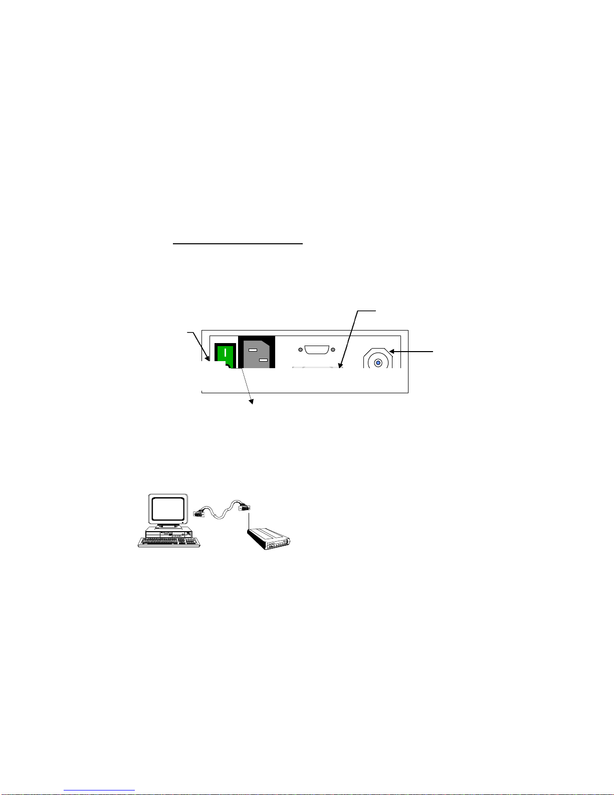
4.1 Hardware Connection
Step 1: Preparation before installation :
Required equipment:
-- two (2) 386/486 IBM PCs with one DB-25 or DB-9 serial port each
-- two (2) straight through serial cables, with a male DB-25 at one end for WINC 900A
and a male/female DB-25/DB-9 at the other end for the serial port of your PC.
Step 2: Cabling
1. Turn your computer off before starting.
2. Connect the DB-25 serial port of the WINC 900A to the serial port of your computer
using a straight through serial cable with RS-232 DB-25 connectors at each end.
(please refer to Fig. 4-2) Although the WINC 900A is configured to accept a DB-25
connector directly, a DB-9 connector may be used with the proper adapter. (The cable with
connector is not supplied with the
WINC 900A, but is available from
most computer retailers and electronics
suppliers.)
3. Connect the power cord to the rear of the unit and plug it into the electrical jack nearest
your equipment. (please refer to Fig. 4-1) The WINC 900A is equipped with a universal
power supply for 110-220 volts and will internally adjust itself for either voltage.
4. Fasten the rubber omni antenna to the antenna connector of the WINC 900A or attach
your Yagi antenna to the antenna connector of the WINC 900A using shielded low lost
cable with TNC to N type connector.
5. Turn on the computer.
N type
Antenna
DB-25 Serial Port
Female Connector
Power Switch
Fig 4-1. Back Panel Layout of WINC 900A
Fig 4-2. Serial Port to Serial Port Connection
AC Power In

9
6. Turn on the WINC 900A modem. The WINC 900A performs a brief self-test via resident
communications software. After the initialization of the communication software on the PC,
the front panel LEDs2indicate the state of the WINC 900A. If cabling is properly done,
the DTR, DSR, CTS and RTS indicators should be green, whereas the RI, DCD, RxD,
and TxD indicators are red after the WINC 900A is initially powered up .
After the completion of the hardware connection between your PC and the WINC 900A , you must
follow the same steps above working on the 2nd unit.
4.2 Communication Software Settings
Although the WINC 900A is a sophisticated wireless modem and integrated spread spectrum
transceiver, it has been designed to be compatible with off-the-shelf communications software
typically used with conventional land-line modems. Consequently, if you have not already done so,
install the appropriate data communications software into your computer before proceeding further.
Please note, due to the popularity of MS-Windows, the Terminal in the Accessories of MS Window
3.1 will be used in the following process as guidance. But, the maximum baud rate of MS
Terminal is 19.200Kbps only; therefore, it requires other communication software to reach
38.400Kbps.
Step 1: Activate your communication software
1. Running MS-Windows, and then activate the Terminal in Accessories.
2. Click the “Settings” ,and then activate the “Communications” dialog box.
Step 2: Configure your communication software to meet default value of WINC 900A
1. Click on the available serial port from the “Connector” list,
2. Click on the 9600 from the “Baud Rate” list,
3. Click on “OK” return to the Terminal.
All selectable items in the communication dialog box will turn into active (high-lighted), if
the selected serial port is available on your computer. Otherwise, stop here and consult
with a computer expert knowledgeable about setting up serial port for you.
Step 3: Communicate with WINC 900A via AT command
1. Press the “Enter” key.
You should get an “ERROR” whenever you press the Enter key without AT commands.
2. Try type in “ATI0”
You should get response similar to the followings:
MODEM address: xxxxxxxx
Current channel: 0
(The MODEM address should match the right-most seven (7) digits of the serial number
digit found on the label affixed to the left side of the unit.)
After the configuration setup process above, the communications software will go into the
local-terminal or direct-connection mode. All AT commands for WINC 900A will be sent
to the serial port directly, accepted and executed by WINC 900A.
2See Section 7.0, WINC 900A Interface Status, for LED indicator definitions.

10
There is a possibility that you will get some funny characters or no response resulting from
the different baud rate settings on the communications software and the WINC 900A. If
this happens, please reset the WINC 900A back to the manufacturer’s default setting --
9600 bps as instructed below.
Whenever you need to clear the settings, you can issue AT command AT&F to reset the
WINC 900A to the original factory default conditions. An alternative method for
accomplishing this is to hold the reset button on the front panel and turn on the power of
WINC 900A. (please refer to Fig. 4-3) A pencil, pen or other sharply pointed object is
required to access the button through the hole on the front panel.
Step 4: Save the configuration settings
of your communications of software
If you already completed the steps above without problems, you may select the “Save” from
the “File” option in the MS-Windows Terminal and save the configuration settings for the
future before you leave Terminal.
If you still have problems communicating with the WINC 900A from your computer, please work on
the followings step by step, and then start all over again from the beginning of this chapter or walk
through our recommendation below.
1. Contact your computer hardware engineer, verify the availability of the serial port (com port) on
your computer, and working on this until the serial port is available to you.
2. Connect your serial port with an external modem and work on the communication software
setting until you get the dial tone, dialing out successfully.
3. Replace the external modem with WINC 900A. At this point, go through the factory default
setting process above to make sure that 9600 is the default baud rate on WINC 900A.
4. Please work from the beginning of chapter 4.0 again.
5. If you still have problems communicating with the WINC 900A, please visit our Web
Customer Support page at www.teletronics.com or fill out the technical support request
form at the last page with all details and fax it to our “Technical Support Team” located in our
US headquarters.
4.3 Communicating with the WINC 900A
Once the WINC 900A and the communications software have been installed, the device is ready to
use. You can communicate directly with the WINC 900A using the AT command set, the
communications software should allow you to put the computer into the local-terminal or direct-
connection mode.
A connection between the local and remote WINC 900A is automatically established on the channel
that provides the best performance. However, if you come across difficulty to operate WINC 900A
on your learning curve. The AT command AT&F is used to reset the WINC 900A to the original
factory default conditions. An alternative method for accomplishing this is to use the reset button on
Teletronics Wireless Modem
DCD
DTR
DSR
CTS
RTS
RxD
TxD
RI
FULL DUPLEX INTERFACE
Power
Signal
Reset
Winc 900A-Car
Default Reset Button Hole
Fig 4-3. WINC 900A Front Panel

11
the front panel of the device. A pencil, pen or other sharply pointed object is required to access the
button through the hole on the front panel.
4.3.1 Establish Connection and Function Test
Step 1. Establish Communication with WINC 900A (execute followings at both PCs)
1. Execute MS-Windows
2. Activate the Terminal in the Accessories
3. Select the Settings, and then click on the “communications” option
4. Click on the available com port from the connectors list
5. Click on the 9600 from the baud rate list.
6. Click on the OK, which will bring you back to the Terminal and stay in the local
terminal mode.
7. Press “Enter” key without AT command. You should get an “ERROR” as response.
Step 2. Establish connection with remote WINC 900A
1. Get the remote station’s address, the right-most seven (7) digits of the serial number
digit found on the label affixed to the left side of the unit.
2. Type in AT connection command ATDT with seven (7) digit remote address as
“ATDTxxxxxxx”.
3. You should get a “CONNECT” as response at both sides.
4. If you did get the “CONNECT” response, you will stay in direct connection mode until
you type in the escape sequence “+++”.
5. If you did not get the “CONNECT” response and system halt. Please reboot the WINC
900A, verify the remote address, and try the AT connection command again.
6. In the connection mode, you may start to type some message on one of your computers
The typed in message will be displayed on the screen of the remote side.
Step 3. Function test on file transfer
1. Click on the “Transfers” from the menu bar of Terminal.
2. Click on the “Send Text File”
3. Select one of the text files from the file list, and then click on OK.
4. You should be able to see the content of the text file on the screen of the remote side.
Also, the transferred file will be created on the remote side, if your friend can help you out
on the remote side, select the “Receive Text File” option from the “Transfers”, and assign a
file name for the in-coming file.
Step 4. Disconnect established link between two WINC 900As
The WINC 900A only responds to AT commands when in the command or off-line mode.
Consequently, to terminate a connection, the unit must escape to this mode before it will
respond. This is accomplished by issuing the escape sequence "+++". Once in the
command mode, the AT command ATH is issued to close the connection.
While the basic AT command set is generic and applies to most land-line modems, a number of AT
commands unique to the WINC 900A are included in Section 7.3. These commands are used to
control air-link specific parameters like the channel number and other operational characteristics.
For completeness, the basic and extended AT command set is described in Section 7.0. In addition,
Appendix A contains the Standard AT Modem Commands and Appendix B contains the S Register
Summary.
12
5.0 Available operation modes in WINC 900A and Applicable applications
Resulting from our long term commitments to our products and tight relationship with our customers,
WINC 900A can be configured to various operation modes as followings:
1. Point-to-Point Dial-up connection mode
2. Point-to-Point Auto connection mode
3. Multiple-to-One Wireless Dynamic Data Reporting and Monitoring (WDDR) mode
4. Multiple-to-Multiple Transparent mode
The first two operation modes, the Point-to-Point Dial-up connection mode and the Point-to-Point
Auto connection mode, were developed on the foundation of the traditional point-to-point
asynchronous mechanism that comes with build-in protocol providing error free data transmission.
In the 3rd operation mode, the Multiple-to-One Wireless Dynamic Data Reporting and Monitoring
operation mode, the build-in broadcasting function transmits the in-coming data from the connected
external device to the air. All remote units operate/broadcast without build-in protocols for packet
collision prevention and packet re-transmission; therefore, the transmitted packets from remote units
might not be received by the information collection unit.
In the Multiple-to-Multiple transparent mode, each WINC 900A operates as a dumb transceiver fully
controlled by industry oriented management systems in transmitting and receiving packet to/from the
air. The correctness of the data is totally relay on the upper level management system. There is
no involvement of build-in protocols from WINC 900A.
5.1 Summary of various operation modes, applicable applications, and FAQ
5.1.1.1 Point-to-Point Dial-up connection operation mode
The spirit of WINC 900A asynchronous modem development is to deliver a wireless
asynchronous modem using traditional dial-up connection mechanism with error free protocol.
The dial-up connection process has been detailed in section 4.3.1. After the establishment of
the point-to-point linkage connection, the user can perform the functionality provided by the
communication software just like the connection established between two PC modems via
telephone line.
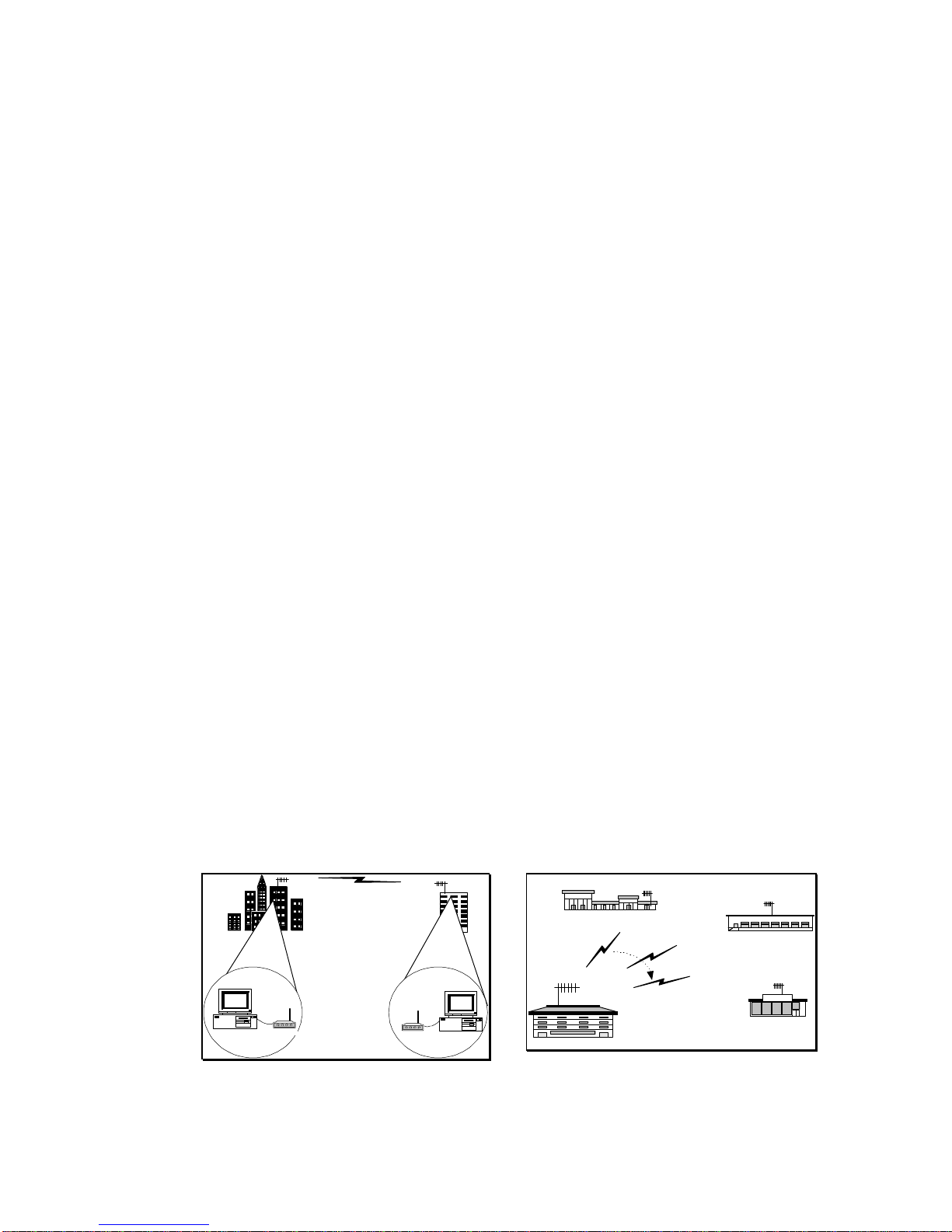
5.1.1.2 Applicable applications
•The traditional remote dial-up connection
•The one-to-multiple polling connection for data distribution or data collection process.
WINC 900A
WINC 900A
Food Mart
Central Office
Branch 1 Branch 2
Branch 3
Traditional Dial-up Connection
The user issues the ATDT command
or activate the connection function
from the communication software to
the remote unit and establish the point-
to-point connection.
One-to-multiple Polling Connection
The user adopts the polling mechnism
in their application program and
initiates the dial-up function to
establish wireless connection with each
remote units by turns.

13
5.1.2.1 Point-to-Point Auto connection operation mode
Besides of the traditional dial-up connection above, a pair of WINC 900A can be operated in
auto connection mode in order to establish a point-to-point permanent wireless linkage.
In the point-to-point auto connection operation, one of the two units will play a roll as Master
unit, the user must issue the following AT commands to specify the address of the slave unit
and to enable the auto connection operation at the Master unit.
AT commands issued at the Master unit to specify the address of the slave unit and to enable the
auto connection function are :
AT~Axxxxxxx
(“xxxxxxx” above stands for the 7 digit address of the slave unit)
AT&!1 (to enable the auto connection function)
After initiating the auto connection operation, the Master unit will issue the connection request
to the specified slave unit, establish connection, and go into connection mode. The Master unit
will automatically recover the established wireless connection after the drop of linkage resulting
from power outage or interference. Before issuing AT commands for configuration change or
terminating the auto-connection function, users must issue the escape sequence, holding the
“Shift” key and pressing “+” key 3 times, to return to the command mode.
5.1.2.2 Applicable applications
•The extended cable connection for dial-up connection.
•The point-to-point perminal link connection
•The leasing line replacement
•The last mile connection
WINC900A
WINC900A
WINC900A
PSTN
WINC900A
ISP
PCModem
Extended cable connection for dial-up
As addressed above, the established
wireless link can be used as wire to
extend the cable wirelessly.
WINC 900A
Last mile extension connection
The established wireless link can be
used as wires between two locations
for data transmission.
Point to-Point Permanent Connection
WINC 900A is the ideal equipment to
establish wireless link for data acquisition
application. WINC 900A has a DC mode.
User is capable to activate the connected
external device at the remote site with
required “BREAK” signal.

14
5.1.3.1 Multiple-to-One Dynamic Data Reporting and Monitoring mode
In the Point-to-Point operation modes above, the build-in protocol ensures that all transmitted
packets between two points will be delivered to the receiver promptly without error. But, in
the Multiple-to-One wireless applications architecture, it is very difficult to specify the break
point of satisfaction on performance with the same guarantee on error free.
For some non-timing sensitive Multiple-to-One applications, WINC 900A can be configured
into three different broadcasting mode as followings :
Operation
Mode AT
command General Description
WINC-900A
Regular Asyn.
Mode
AT~P1 refer to manual 5.1.1 section
WINC-900
Multiple
Broadcast
Mode
AT~P2 Monitor unit stays in monitor mode and receives all data
packet on the air. User can activate the broadcasting
function of specific slave unit at remote site.
WINC-900
MultipleAuto
Broadcast
Mode
AT~P5 Monitor unit stays in monitor mode and receives all data
packet on the air. The broadcasting function of the slave
unit is activated automatically after power on.
WINC-900
Multiple
Transceiver
Mode
AT~P6 Both monitor and remote units are staying in monitor mode
and receive all data packet on the air. Monitor and
remote units will switch into broadcasting mode by in-
coming data from the connected external device and transmit
received data from connected external device to the air.
Due to the nature of the broadcasting mechanism and the inter-change between transmission and
receiving, the transmitted data packets from all slave units might not be received fully by the
monitor unit.
We are going to walk through configuration steps for AT~P5 operation mode and related AT
command sets briefly in the following : (Please downloads WDDR user manual from our Web
site, if you do further technical information)
Step 1 :
Operation mode setting and review using AT command sets.
Leasing line replacement
Due to the build-in error free protocol and
the connection auto-recovery capability, the
wireless connection established by WINC
900A is the ideal to be used in replacing the
costly leasing line.

15
AT~P5 to switch from Point-to-Point operation mode to Multiple-to-One operation
mode. User can switch back to Point-to-Point operation mode using
AT~P1 command.
Step 2 :
0 -- channel 0, 1, 2, 3, 4, 5, 6, 7 1 -- channel 0 only (925 MHz)
2 -- channel 1 only (922 MHz) 3 -- channel 2 only (919 MHz)
4 -- channel 3 only (916 MHz) 5 -- channel 4 only (913 MHz)
6 -- channel 5 only (910 MHz) 7 -- channel 6 only (907 MHz)
8 -- channel 7 only (904 MHz) 9 -- channel 0, 1, 2, 3 (non-GSM)
10 -- channel 4, 5, 6, 7 11 -- channel 0, 2, 4, 6
12 -- channel 1, 3, 5, 7 13 -- channel 0, 2
14 -- channel 4, 6 15 -- channel 1, 3
16 -- channel 5, 7
Step 3 :
5.1.3.2 Applicable application
•The fleet management system
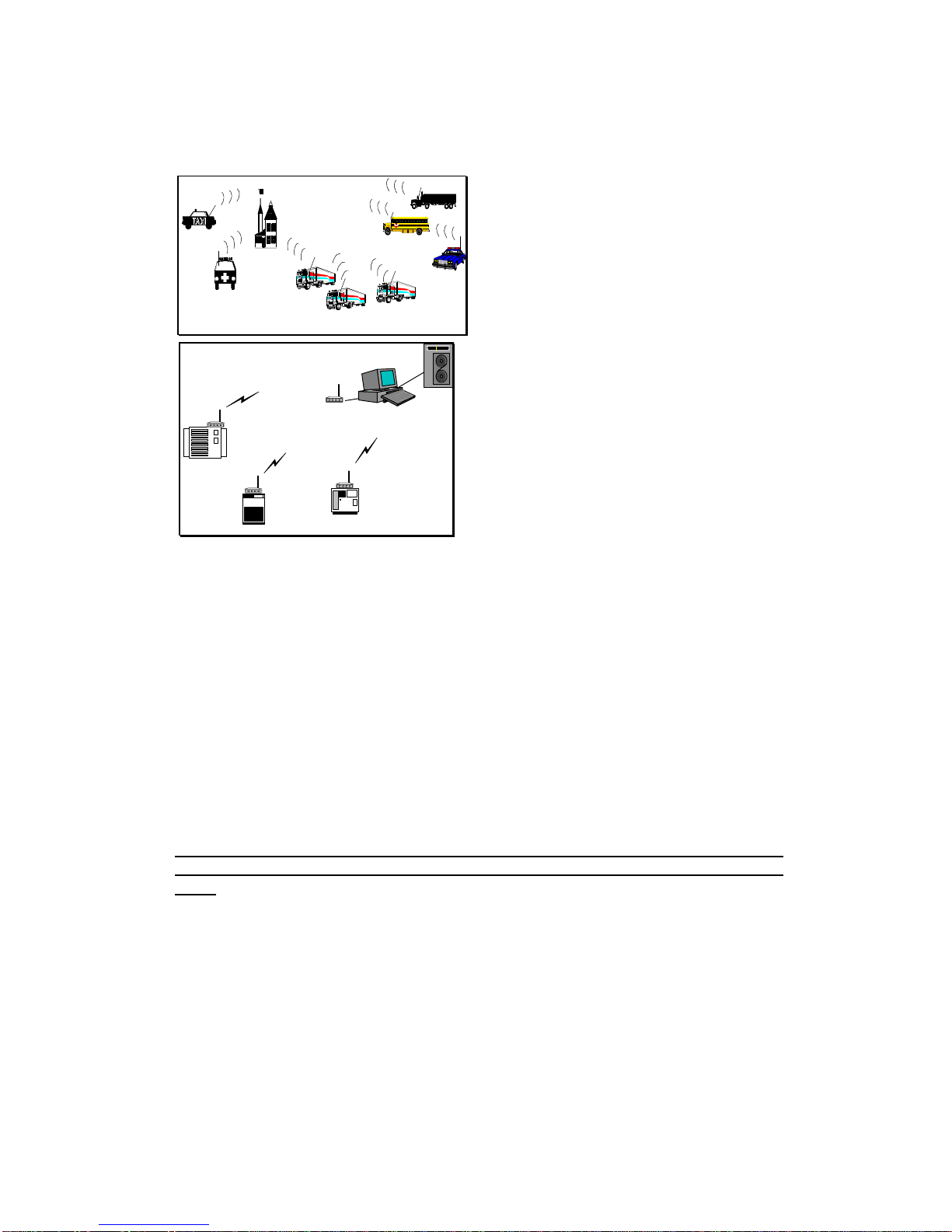
16
•The remote device monitoring system
5.1.4.1 Multiple-to-Multiple
Transparent operation mode
For some one-to-multiple, multiple-to-one or multiple-to-multiple applications, a fully
controlled transmitting and receiving two way capability is required. To meet this
requirement, our WINC 900A can be configured as dumb transceiver fully controlled by higher
level application system.
The configuration steps and related AT command sets for setting are briefed in the following :
AT&!E to switch into transparent mode from point-to-point operation mode.
AT&!Q to return to point-to-point operation mode from transparent mode.
AT\Cn to specify the operation channel from 0 to 7.
this operation channel must be specified before changing WINC 900A
operation mode from the point-to-point to transparent. Otherwise, units
can not receive packets.
Please note, the transparent mode can not be terminated by restoring manufacture
default or hardware reset process. User must issue “AT&!Q” to exit the transparent
mode.
5.1.4.2 Applicable application
•The multiple-to-one remote data acquisition application
•The one-to-multiple remote control application
R1
R2 R3 R4 R5
R6
R7
R8
WINC 900A
Mobile location and Fleet management system
WINC 900A can be configured into broadcast
mode transmitting bus location or other
information from each buses to the air and the
designated monitoring unit will receive the
transmitted packet in the air. The monitor unit
will do its best to receive packets, but some
packets might not be collected accordingly.
Remote sensor reporting system
For some of those non-timing sensitive operations,
the build-in broadcast mode above is also
applicable for data acquisition or monitoring
applications.

17
•The multiple-to-multiple data exchange application
5.2 FAQ and System Adjustment
The behaviors of WINC 900A are adjustable via the AT commands and the content of register
in order to meet the requirement of you application To speed up your learning curve, the
following FAQ will play a roll as index for your reference. Please refer to the APPENDIX B -
S Register Summary for details.
1. How to enable the auto-answering function of your modem ?
Please refer to the value of register 0.
2. How can I issue an AT command again after the dial-up connection has been
completed, or in the auto connection mode, or in the transparent mode ?
Please refer to the Escape Character in the register 2 and 12.
3. Can I change the time-out length of connection request process ?
Please refer to register 7 for details.
4. How long this modem will take to declare lost link with its remote unit after
linkage drop and ready for another connection request from remote unit ?
Please refer to register 10.
5. How long the in-coming data from the connected external device will stay in
the data buffer before transmission ?
Please refer to register 50.
6. How can I reduce the waiting period and speed up the transmission process
of the in-coming data from the connected external device ?
Please refer to register 51 and 52.
7. Where can I find the remote unit’s address if the connection request was
initiated from remote unit ?
Please refer to register 53.
8. How long the RF of WINC 900A will remain in burst mode after connection
or data transmission ?
Please refer to register 60.
9. How can I disable the idle mode ?
WINC 900A
Multiple-to-one remote data acquisition
and one-to-multiple remote control
application
The WINC 900A can be configured to be a
dumb transceiver. It can be controlled by
some managing and monitoring oriented
application software and devices that come
with build-in device ID verification and
communication protocol.
Multiple-to-multiple data exchange application
Due to the characteristic of transparent mode
provided by WINC 900A, the transmitted packets
from one node can be received by multi-nodes
(multiple WINC 900As) on the same channel.
With the support of upper level protocols, a
wireless net can be formed among WINC 900As.

18
Please refer to register 60.
10. How can I adjust the polling pace from the master unit in the idle mode ?
Please refer to register 61.
11. How can I adjust the length of the “BREAK” signal in order to activate the
connected external PLC or SCADA device ?
Please refer to register 62.
12. How can I adjust the length of the carry detection function in the transparent
mode ?
Please refer to register 63.

19
6.0 WINC 900A Interface Status
The WINC 900A interface status refers to the state of the RS-232 serial port between the local
terminal or computer and the WINC 900A. The state, in turn, is determined by the signal levels on
each of the signal lines that comprise the serial port. These status lines have been brought to the
front panel in the form of a series of eight (8) light emitting diodes (LED). In addition, a reset button
has been provided to the right of this series of LEDs.
To the right of the reset button are two additional indicators, one above the other and each
rectangularity shaped. When the unit is powered on, the upper indicator turns red and stays red until
the unit is powered down. The lower indicator provides a measure of the receive signal strength.
When the indicator is green, the receive signal on the current channel is sufficiently strong to
maintain a connection with the remote terminal. A weak signal will cause the indicator to turn off.
Each LED displays one of two different colors, green or red. Green indicates an active state or signal
presence, whereas red indicates an inactive state or signal absence. The table below indicates the
function of each signal beginning with RI, the left most indicator. The remaining indicators appear
from left to right ending with RXD, the right most indicator.
Panel L E D Function
Ring Indicator (RI) Signals incoming connection request.
Data Carrier Detect (DCD) Indicates "connection established" with remote.
Data Terminal Ready (DTR) Signal from host to device. May indicate command mode
escape or ignored by device.
Data Set Ready (DSR) Signal from device to host. May indicate connection
established or always on.
Clear To Send (CTS) Indicates device ready to accept data from host. Used in H/W
flow control.
Request To Send (RTS) Indicates host ready to send data to device. Used in H/W flow
control.
Receive Data (RXD) Serial data input to host from device.
Transmit Data (TXD) Serial data input to device from host.
When the WINC 900A is initially powered up the CTS and DSR indicators should be green, whereas
the RI and DCD indicators are red.
Once the connection is established, the DCD indicator turns green.
If the system is configured to use hardware flow control the CTS indicator will change to RED when
the WINC's internal buffer becomes full. When data is removed from the buffer the CTS indicator
will turn green again.
When a connection request from a remote terminal is received the RI turns green. It will turn red
when the connection is established or the connection request has timed out.
The DTR, DSR, RTS, and CTS indicators follow the AT configuration commands as issued to the
WINC 900A. For example, if the device has been configured for S/W flow control then the RTS and
CTS indicators will be red.

20
Since the WINC 900A alternatively transmits and receives when on-line, the TXD and RXD
indicators cycle between green and red at the configured data rate.
When the default reset button is pressed, the WINC 900A either defaults to the factory preset
configuration of 9600 bps, 8 bits per character, no parity, 1 stop bit, hardware flow control, and auto
answer or resets to the previously configured state. To ensure that the device resets to the default
conditions, first power down the unit and then power it on while depressing the reset button.
To the right of the serial line LEDs are two small rectangular LED indicators. The upper red
indicator lights when the power is on, while the lower green LED indicates the receive signal level.
Solid ON indicates sufficient signal strength, while solid OFF indicates either no received signal or a
signal too weak to sustain communications. A blinking signal indicates a marginal signal level.
If you experience difficulty in making connections between a local and remote WINC 900A, first
reset both units to the factory default conditions and retry before calling for technical assistance.
Table of contents
Other Teletronics International Modem manuals


