LED Description Function
off CTS inactiveCTS Clear to send
green The CTS is
switched on when
the carrier is being
established. A
transmit delay time
of 20-30ms has to
be adjusted in DTE
settings.
off No signal receivedDCD Data carrier
detected green Modem signal
received
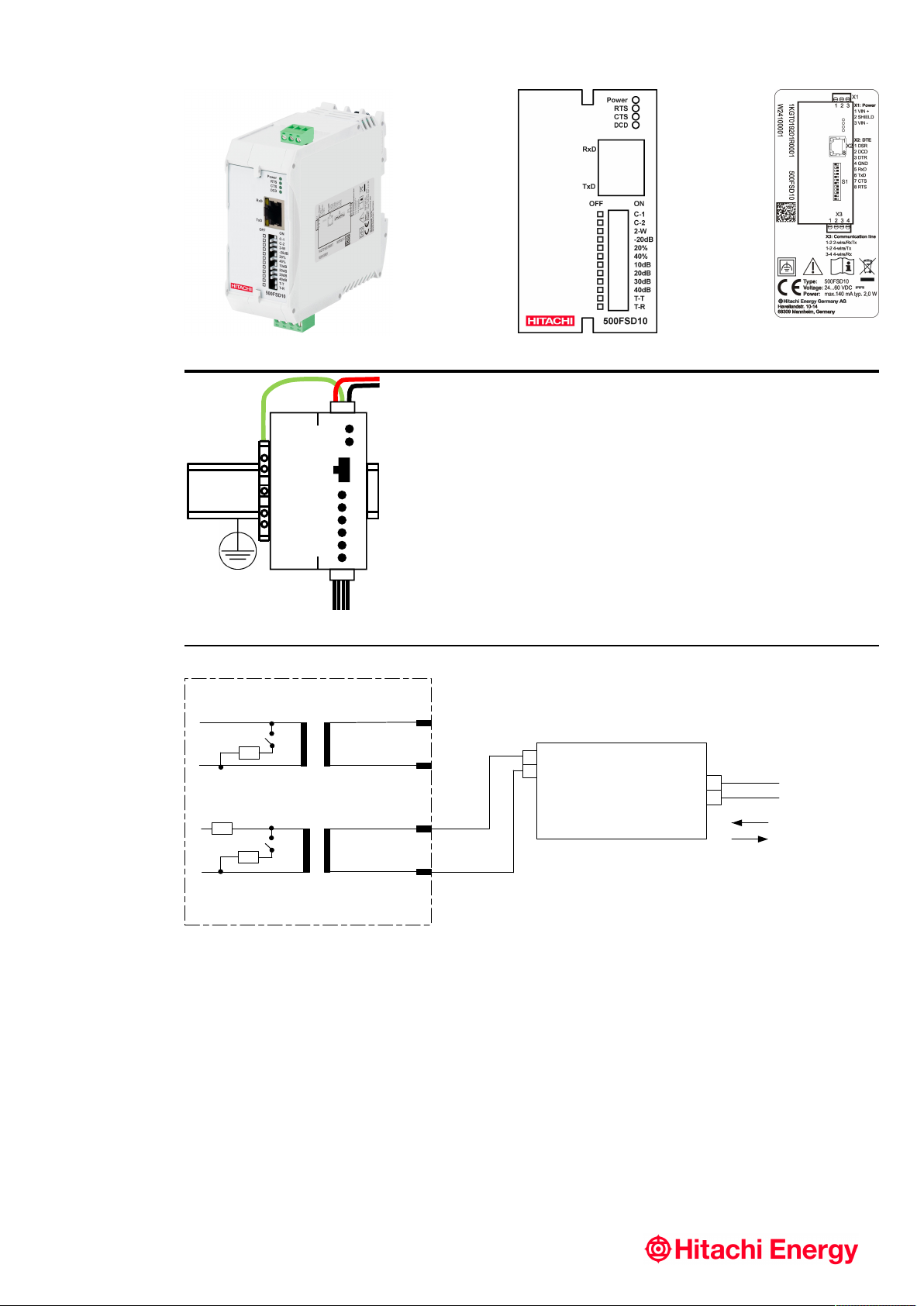
Settings
The DIP-switch S1 establishes the mode of operation of
the modem.
Switch C-1 is reserved for future use.
Switch C-2 establishes a permanent carrier on the line
which is useful in a four-wire fullduplex connection.
Switch 2-W distinguishes between two-wire and four-
wire operation of the modem. In two-wire mode X3-1 and
X3-2 form terminal NF1 which is used for transmission
and reception. In four-wire mode X3-1 and X3-2 form
the transmitter terminal NF1 and X3-3 and X3-4 form the
receiver pair NF2.
The next three switches belong to the transmitter
amplitude. In a long multi-drop line configuration, where
the modem in the central needs a high amplification factor
to receive the signal of the last modem, the transmission
level of the modem next to the central station can be
reduced by 20 dB with the –20dB switch. This is done
to avoid overdrive of the receiver in the central station
modem. To compensate a low-pass character of the
transmission line, the amplitude of the upper transmission
frequency can be increased by 20 %, 40 % and 60 %. If
both switches 20% and 40% are ‘off’, no increasing of the
amplitude takes place.
The 500FSD10 has five predefined receiver amplifications:
0 dB, 10 dB, 20 dB, 30 dB and 40 dB. These are set by
the switches 10dB to 40dB. Only one amplification DIP
switch is allowed to be in the 'on' position at a time.
If the 500FSD10 is to be terminated with the line
impedance, the DIP switches T-T and T-R need to be
switched to 'on'. This is usually the case at both ends of
the line. If the modem is to be connected in a party-line
manner in between, these DIP switches have to be ’off’.
T-T terminates the low frequency (LF) line NF1, which
is formed by terminals X3-1 and X3-2. T-R terminates
the receiver pair NF2 of the four-wire configuration with
terminals X3-3 and X3-4.
left – ‘off’ right – ‘on’
C-1 for future use for future use
C-2 switch on sender
with RTS
carrier always
active (four-wire)
2-W four-wire mode two-wire mode
-20dB normal sending
power
decrease sending
power by 20 dB
left – ‘off’ right – ‘on’
20% raise upper
frequency
amplitude by 20 %
40%
both raising
factors active:
60 % of upper
frequency
amplitude, none
active: no raise
raise upper
frequency
amplitude by 40 %
10db 10 dB amplification
20db 20 dB amplification
30db 30 dB amplification
40db
only one factor
allowed to be
active, all off: 0 dB
40 dB amplification
T-T no termination
NF1 (> 6 kΩ)
line termination
NF1
T-R no termination
NF2 (> 6 kΩ)
line termination
NF2
Safety
DANGER
Interrupt the power supply before mounting or
dismounting the device.
WARNING
An easy to access manual interrupter has to be
installed into the power feed of the modem to be able
to disconnect the modem from the power supply in the
case of an emergency.
WARNING
The EDS500 devices are intended only for use in
restricted access area. For fire protection the devices
have to be mounted into suitable cubicles which are
certified for the function of a fire protection housing.
WARNING
The DC power supply has to fulfil the following
requirements in order to supply appropriate fire
protection:
•Limited power source according to IEC 60950-1 or
PS2 classified according to IEC 62368-1
•Short-circuit current < 8A
WARNING
The device shall be powered off while accessing any
of the connectors X1 (power connector) or X4 (alarm
relay). Any other connectors (e.g. RS-232 or 4-wire/2-
wire communication port/X3) are hot-pluggable while
the device is operating.
WARNING
No plug shall be freely accessible in normal operation
due to safety reasons.