BELL SYSTEM PRACTICES
AT&TCo
Standard
SECTION 582-211-700
Issue 3, April
1979
"DATASPEED*"
40
OPERATOR CONSOLES
KD AND RO
DlSASSEMBL
Y/REASSEMBLY, ADJUSTMENT, AND PARTS
CONTENTS PAGE
1.
GENERAL.
. . . . . . . . . . . . . . . . . . . . 1
TOOLS
REQUIRED.
. . . . . . . . . . . . . 2
2.
DISASSEMBLy/REASSEMBLy.....
2
KDOPCON.....................
2
A. Rem.oval
..................
.
B.
Replacement
...............
.
C.
Key
top
Conversions -
40K101
Opcon
Only
.........
.
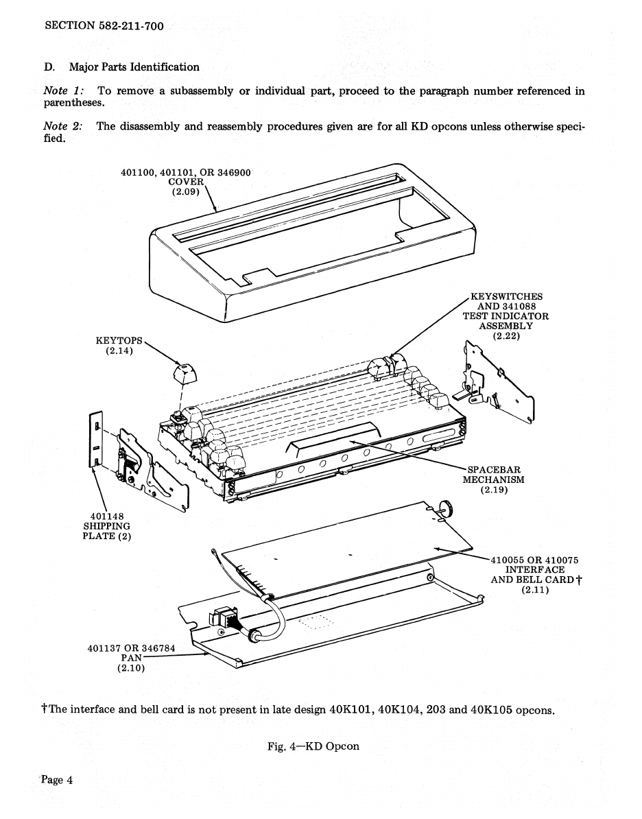
D. Major Parts Identification
.....
.
E. Disassembly/Reassembly
......
.
2
2
3
4
5
RO
OPCON.....................
11
A. Removal and Replacement . . . . .
11
B.
Key
top
Conversions . . . . . . . . . .
11
C.
Major Parts
Identification.
. . . . . 11
D.
Disassembly/Reassembly.......
12
3. ADJUSTMENT. . . . . . . . . . . . . . . . . .
16
COVER TO KEYTOP
ADJUSTMENT........
..........
16
4. PARTS
.........................
17
NUMERICAL INDEX
............
.
31
1. GENERAL
1.01
This section providesdisassembly/reassem-
bly, adjustment, and parts information
for
the
two
basic
types
of
DATASPEED
40
operator
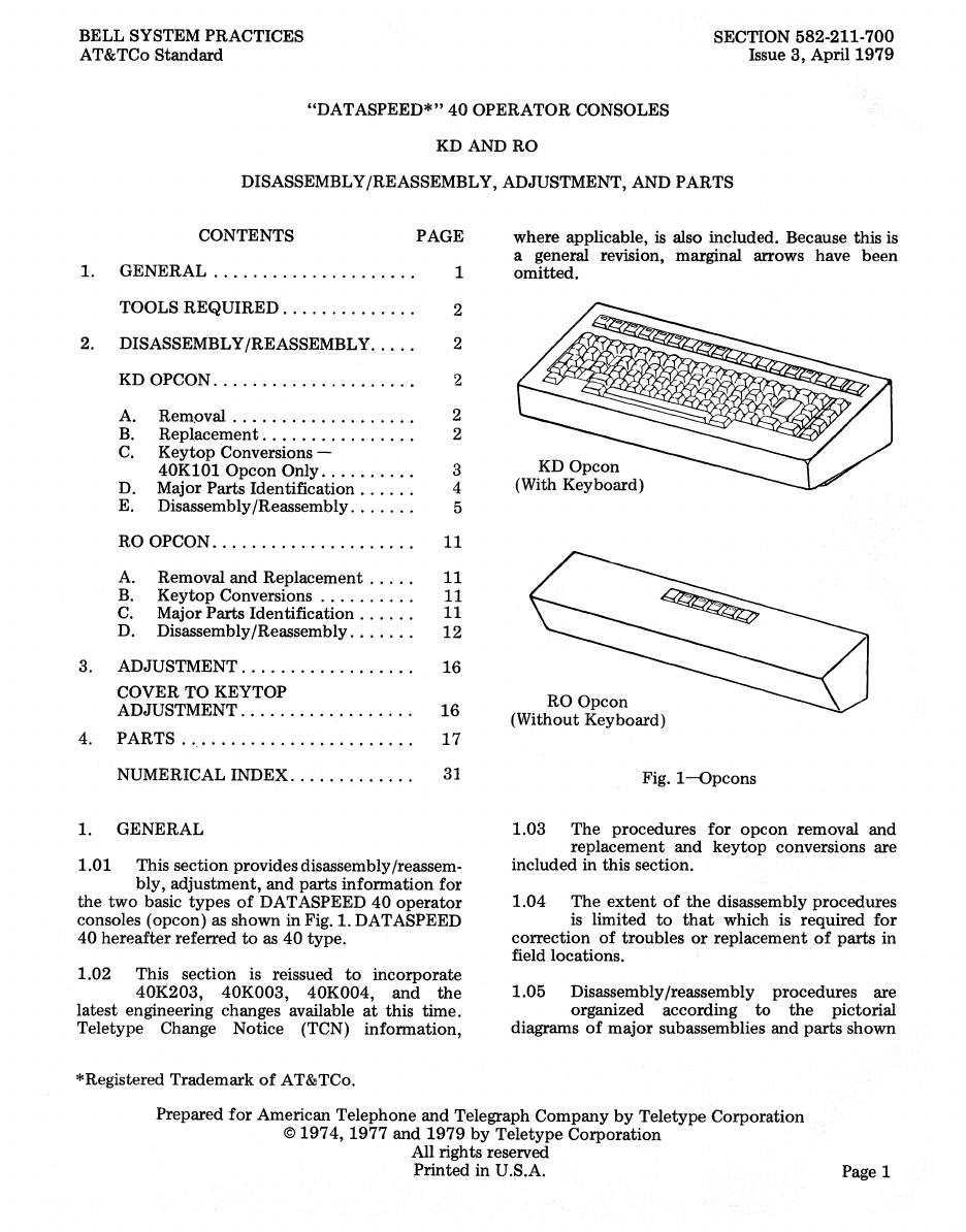
consoles (opcon) as shown in Fig. 1. DATASPEED
40
hereafter
referred
to
as
40
type.
1.02 This section is reissued
to
incorporate
40K203, 40K003, 40K004,
and
the
latest engineering changes available
at
this time.
Teletype Change Notice (TCN) information,
*Registered Trademark
of
AT&TCo.
where applicable,
is
also included. Because this is
a general revision, marginal arrows have been
omitted.
KD Opcon
(With Keyboard)
RO Opcon
(Without Keyboard)
Fig.
1-opcons
1.03
The
procedures
for
opcon
removal and
replacement
and
key
top
conversions are
included in this section.
1.04
The
extent
of
the
disassembly procedures
is limited
to
that
which is required
for
correction
of
troubles
or
replacement
of
parts
in
field locations.
1.05
Disassembly/reassembly procedures are
organized according
to
the
pictorial
diagrams
of
major
subassemblies and
parts
shown
Prepared
for
American Telephone and Telegraph
Company
by
Teletype Corporation
©
1974,1977
and
1979
by
Teletype Corporation
All rights reserved
Printed
in U.S.A. Page 1