2. 13 Refer to the appropriate wiring diagrams
packed with the teletypewriter set.
2. 14 Connect the signal line leads (supplied
by customer) to the terminals on the
terminal board at the rear of the call control
unit as indicated in the wiring diagram.
2. 15 Connect power cord to an ac source, 115
volt 60 Hz.
2.16 CheckDASHPOT ORIFICE(Spacing Area)
adjustment, since altitude may have
some effect on dashpot operation. See Section
57
4-122-700TC.
2.17 Sets equipped with an answer-back mech-
anism must be tested for proper response
to a predetermined call character suchas WRU.
The following procedure is recommended for
performing this test.
(a) Use a predetermined call character such
as WRU, to call in the newly installed set.
(b) The set should establish the connection
and automatically transmit the answer-
back message.
Note: Set will not respond if the suppres-
sion tine has been removed from the last
row. See 2. 07 (b).
(c) If proper response is not obtained, check
and correct the answer-back area adjust-
ments (Section 574-122-700TC), beginning
with those of the following list.
DRUM POSITION
TRIP LEVER CLEARANCE
FEED PAWL POSITION
FEED LEVER POSITION
"HERE-IS" BELLCRANK POSITIONING
TRIP BAIL POSITIONING
CHARACTER SUPPRESSION CONTACT
WIRE GAP
2. 18 The 33 Teletypewriter Sets are shipped
from the factory with the automatic car-
riage return-line feed feature in the typing unit
ISS 6, SEC'l'ION 574-100-201 TC
disabled by means of clips. The clips mount
over slots in the TP180950 front tie bar. To
enable this feature on friction feed sets remove
the clip over slot A. To enable this feature on
sprocket feed sets remove the two clips, in slot
A and slot L.
Note: Slot A is not stamped on the function
casting. Refer to 574-122-700TC for orien-
tation.
2. 19 Connect the signal line leads (supplied
by customer) to the terminals on the
terminal board at the rear of the call control
unit as indicated in the wiring diagram.
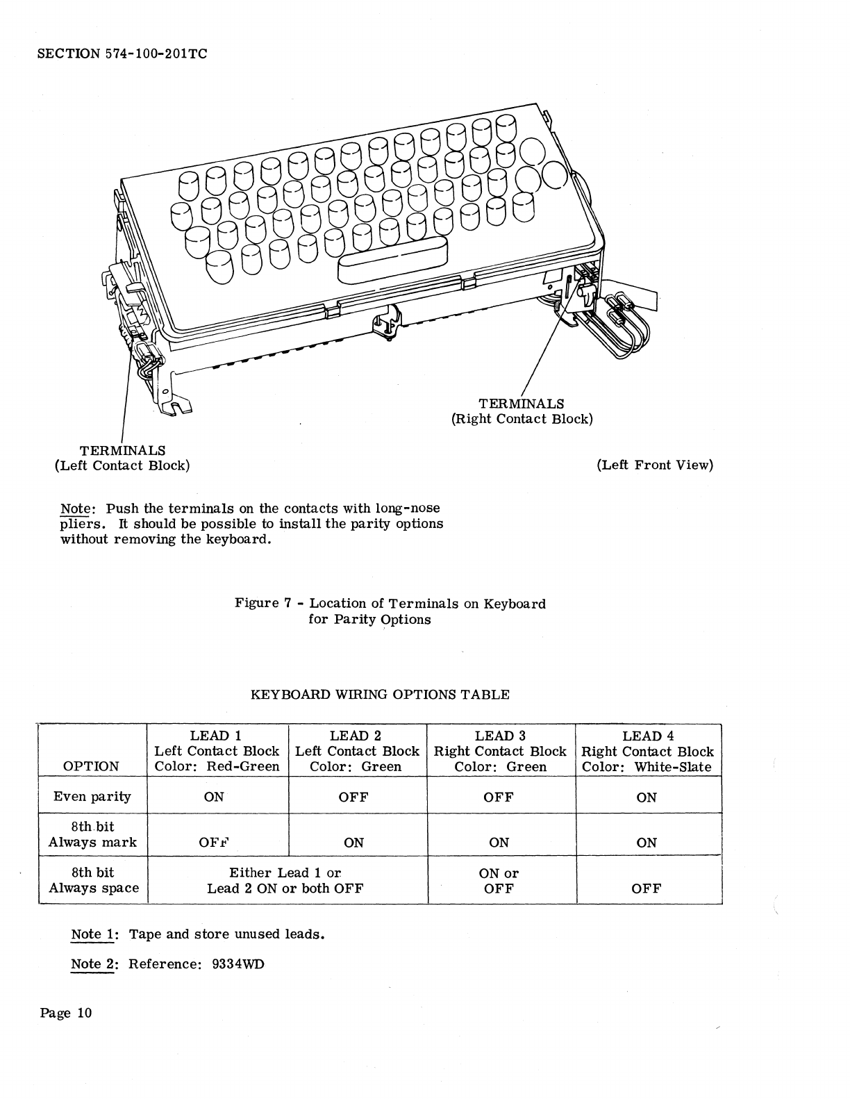
2. 20 The 33 Teletypewriter Sets are shipped
from the factory with the even parity
option installed in the keyboard. The customer
may:
(a) Retain even parity, or
(b) Wire the keyboard for the 8th bit always
marking, or
(c) Wire the keyboard for the 8th bit always
spacing.
The wiring options are installed by connecting
wires to terminals at the right front of the key-
board and at the left contact block (see Figure 7).
The options are shown in the Keyboard Wiring
Options Table.
2. 21 Low Tape Contact Adjustments (for units-
so equipped): -
(a) Operating Arm Adjustment (Figure 8):
Replace cover. With tape spindle in
place, there should be 5/16 inch to 7/16 inch
clearance between operating arm and tape
spindle. To adjust, bend operating arm.
(b) Operating Arm Clearance (Figure 9):
Remove cover. The operating arm
should have a minimum of 1/8 inch clearance
Page 9