TABLE
OF
CONTENTS
HOW
TO OPERATE INSTRUCTIONS
Introduction
. . . . . . . . . . . . . . . . . . . . . . . . . . . .
..
1
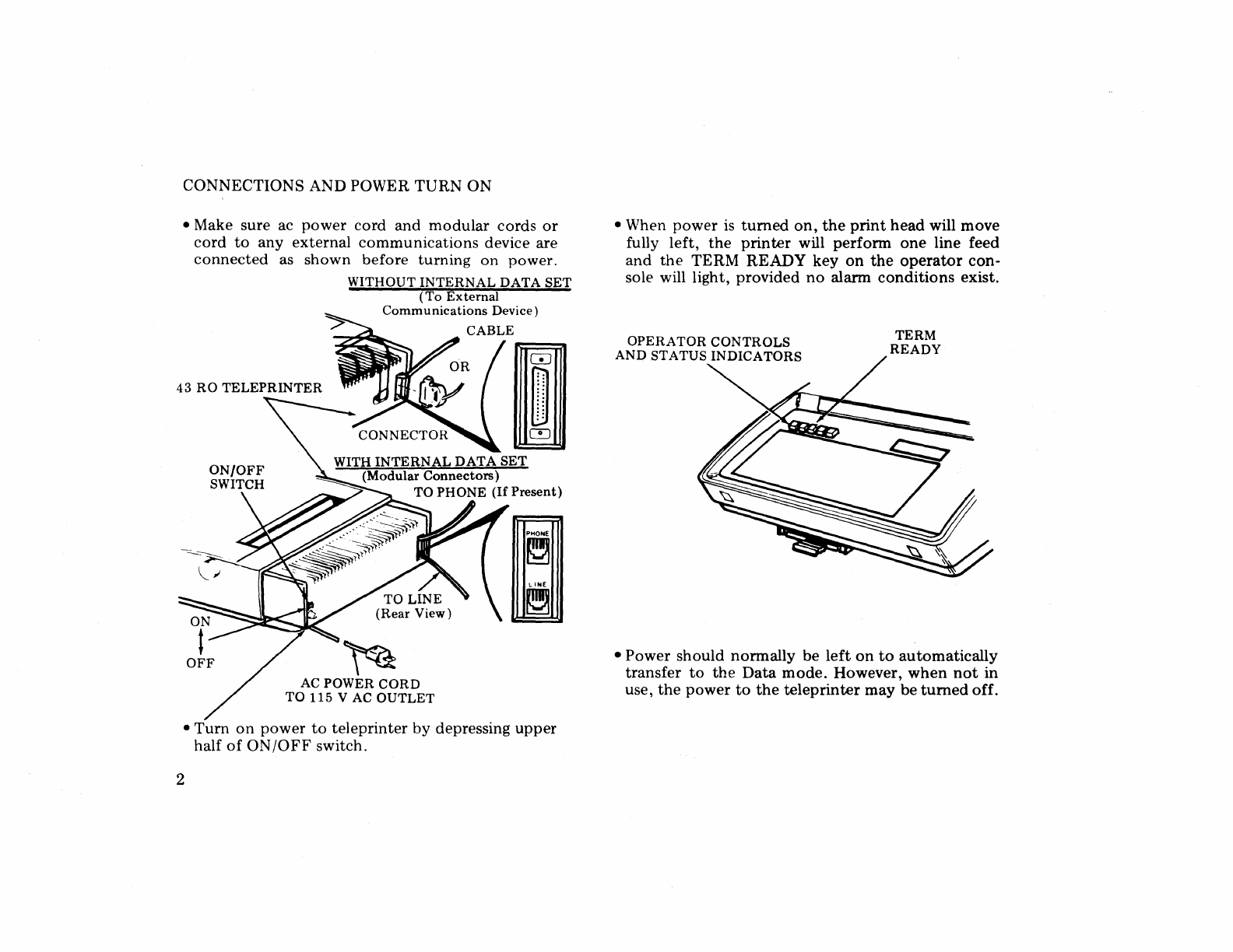
Connections
and
Power
Tum
On. . . . . . . . . . . . .
..
2
Operational Controls
and
Status
Indicators
.......
3
Communications With
Distant
Terminals
........
4
Prin
ter
Operation . . . . . . . . . . . . . . . . . . . . . . . .
..
5
Teleprinter Supplies Maintenance
..............
6
Installing Paper
(Sprocket
Feed) . . . . . . . . . . . . .
..
7
Installing Paper (Friction Feed). . . . . . . . . . . . . .
..
8
Installing Ribbon. . . . . . . . . . . . . . . . . . . . . . . . .
..
9
SUPPLEMENTARY OPERATIONAL INFORMATION
Printer Test and Reset Keys . . . . . . . . . . . . . . . . . .
10
TERM READY Key
........................
11
DATA Key
...............................
12
ALARM Key. . . . . . . . . . . . . . . . . . . . . . . . . . . . . .
13
Telephone Calls. . . . . . . . . . . . . . . . . . . . . . . . . . . .
14
Special Characters
..........................
15
When Trouble Occurs
.......................
16