MANUAL
373, 2-1
PART
2
--
INSTALLATION
A.
VARIABLE
FEATURES
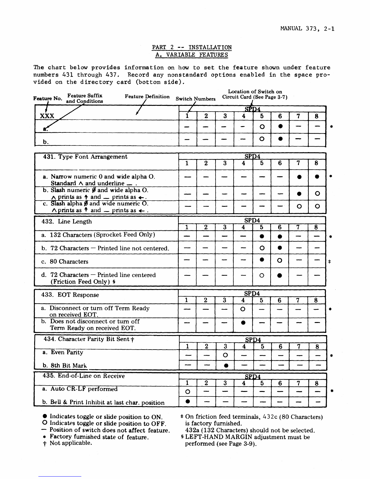
The
chart
below
provides
information
on
how
to
set
the
feature
shown
under
feature
numbers 431
through
437.
Record
any
nonstandard
options
enabled
in
the
space
pro-
vided
on
the
directory
card
(bottom
side).
Feature
No
Feature
Suffix
i .
and
Conditions
Feature
Definition
S
't
h N b
/
WI
C / urn ers
Location
of
Switch
on
Circuit Card (See Page 3-7)
X~X
/ I
~
b.
431.
Type
Font
Arrangement
a. Narrow numeric 0
and
wide alpha O.
Standard
1\
and underline _ .
b. Slash numeric S
and
wide
alpha
O.
" prints as ,
and
_
prints
as
+-.
c. Slash alpha
~
and
wide
numenc
O.
1\
prints
as , and -
prints
as
~
.
432. Line Length
a.
132
Characters
(Sprocket
Feed Only)
b.
72
Characters -Printed line
not
centered.
c.
80
Characters
d.
72
Characters -Printed line centered
(Friction Feed Only) §
433. EOT Response
a. Disconnect
or
turn
off
Term Ready
on
received EOT.
b. Does
not
disconnect
or
tum
off
Term Ready
on
received EOT.
434. Character Parity Bit
Sent
t
a. Even Parity
b.
8th
Bit
Mark
435. End-of-Line
on
Receive
a.
Auto
CR-LF performed
b.
Bell & Print
Inhibit
at
last char. position
• Indicates toggle
or
slide position
to
ON.
o
Indica~s
toggle
or
slide position
to
OFF.
-Position
of
switch
does
not
affect
feature.
•
Factory
furnished
state
of
feature.
t Not applicable.
j
L
SP:
D4
1 2 3 4 5 6 7 8
----0 • - -
----0 • --
SPD4
1 2 3 4 5 6 7 8
------• •
----- - • 0
------0 0
SPD4
1 2 3 4 5 6 7 8
-- - -• • --
----0 • --
--- - • 0 --
----0 • --
SPD4
1 2 3 4 5 6 7 8
---0 ----
-- - • - - --
SPD4
1 2 3 4 5 6 7 8
--0 ---- -
--• --- - -
SP:
D4
1 2 3 4 5 6 7 8
0 ---- - --
• ---- - --
:I:
On
friction feed terminals, 432c
(80
Characters)
is
factory furnished.
432a
(132
Characters) should
not
be selected.
§
LEFT
-HAND MARGIN
adjustment
must
be
performed
(see Page 3-9).
•
•
•
•
•
•