BELL SYSTEM PRACTICES
AT&TCo Standard SECTION 582-202-200
Issue
2,
December
1980
INTEGRATED SYNCHRONOUS "DATASPEED*" 40
RECEIVE-ONLY PRINTER (ROP) STATION
INSTALLATION
CONTENTS PAGE
1.
GENERAL.
. . . . . . . . . . . . . . . . . . . . 1
2.
TECHNICALDATA..............
3
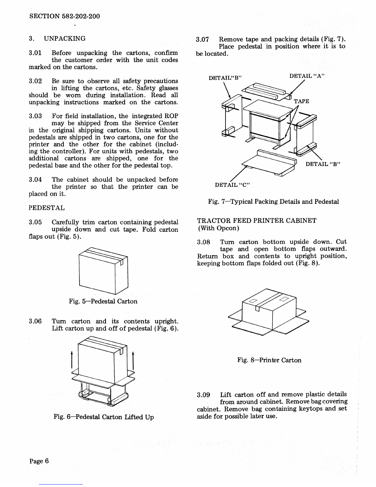
3.
UNPACKING...................
6
PEDESTAL............
....
.....
6
TRACTOR FEED
PRINTER CABINET . . . . . . . . . . . . . 6
FORMS ACCESS
PRINTER
CABINET.
. . . . . . . . . . . . 7
4. PREOPTIONING DISASSEMBLY . . . 8
5. FIELD OPTIONS AND
DESCRIPTIONS. . . . . . . . . . . . . . . . .
10
PRINTER OPTIONS.
..
. . . . . . . . . . .
10
CONTROLLER
OPTIONS.
. . . . . . . .
13
GROUND
OPTION.
. . . . . . . . . . . . . . 21
6.
OPTION
ACTIVATION.
. . . . . . . . . . 22
TRANSMITTING CODES. . . . . . . . . .
29
ACTIVATING PRINTER
OPTIONS......................
33
ACTIVATING CONTROLLER
OPTIONS......................
48
ACrIVATING DATA SET
OPTIONS......................
59
7. FINAL ASSEMBLY. . . . . . . . . . . . . .
64
1.
GENERAL
1.01 This section contains information
for
installing
the
Integrated Synchronous
DATASPEED
40
Receive-Only Printer (ROP)
Station. The Integrated Synchronous ROP
is
used in
the
following services: (2) Switched-
Network using
Data
Set 201C, 208B
or
212A,
(2) Multipoint Private Line using Data Set 201C,
208A
or
209A;
and
(3) Two-Point Nonselective
Private Line (point-to-point private line) using
Data Set 201C,
208A
or
209A.
1.02
This section
is
reissued
to
include
Option
179
(WACK/BUFFER Control)
and
information pertaining
to
Data
Set 212
and
forms
access arrangements. Since thisis a generalrevision,
no revision arrows have been used
to
denote
significant changes.
Note: When ordering tools
or
replaceable com-
ponents, unless otherwise specified, prefix each
part
number
with
the
letters
"TP"
(ie,
TP406173).
1.03
Circuit Card Handling Procedures:
Warning: To avoid possible internal damage
to the MOS devices,
or
card with MOS devices,
due to electrical static discharge by service per-
sonnel, the following should be observed.
All
personnel handling MOS devices, or circuit
cards with MOS devices,
must
wear a
346392
static discharge strap adjusted to make firm
contact with the skin at all
timest(Fig.
1).
t Service personnel are never
to
be
connected
directly
to
ground
but
rather
through a high
resistance discharge
path
of
a minimum
of
one
megohm where
115
V ac
is
present. This resis-
tance
is
built
into
the
346392
static discharge
strap.
Prepared for American Telephone
and
Telegraph Company
by
Teletype Corporation
©
1978
and
1980
by
Teletype Corporation
All rights reserved
Printed in U.S.A. Pagel