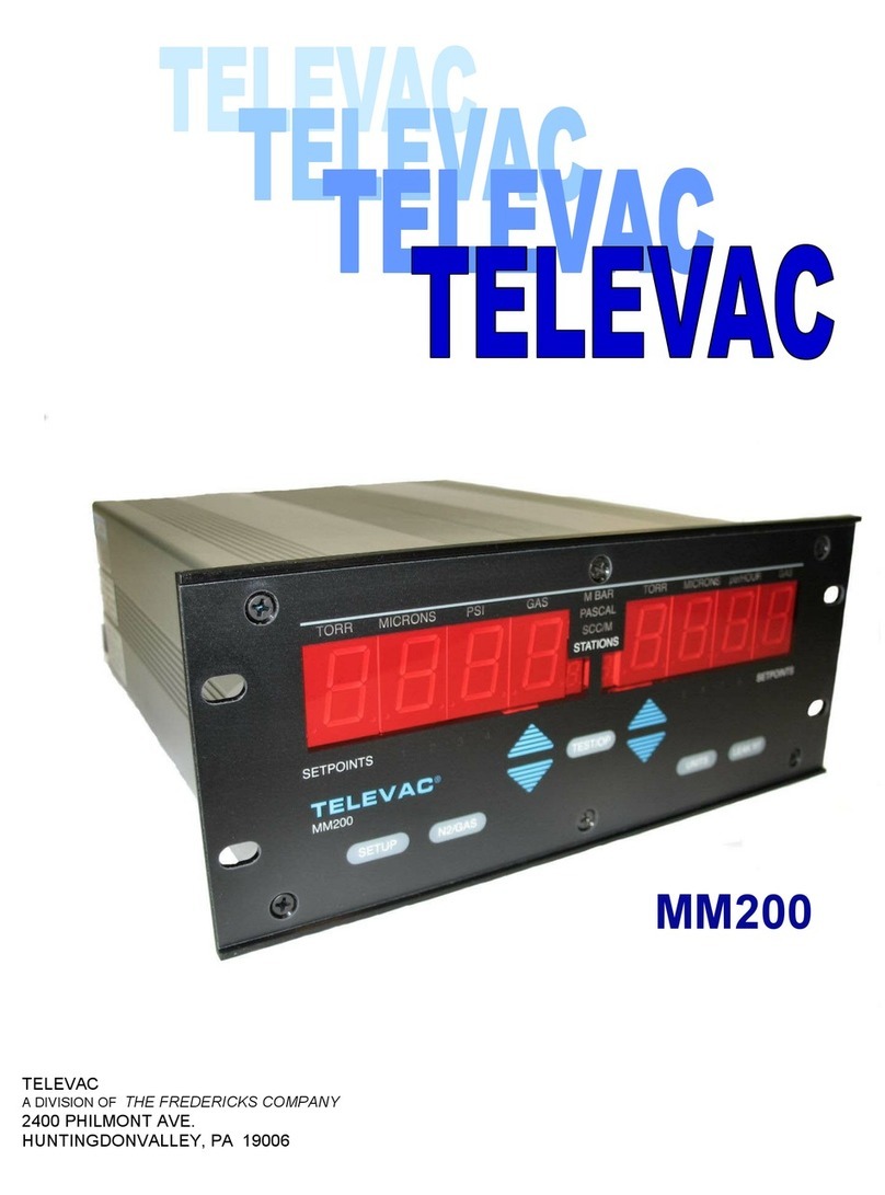
TELEVAC MC300 User manual

The Fredericks Company
MC300 Vacuum Sensor Controller
Instruction Manual
The Fredericks Company - Televac
2400 Philmont Avenue
Huntingdon Valley, PA 19006
web: www.frederickscompany.com
email: [email protected]
tel: +1 215 947 2500
fax: +1 215 947 7464

CONTENTS CONTENTS
Contents
1 Introduction . . . . . . . . . . . . . . . . . . . . . . . . . . . . . . . . . . . . . . . . . . . . . . . . . . . 3
1.1 Disclaimer . . . . . . . . . . . . . . . . . . . . . . . . . . . . . . . . . . . . . . . . . . . . . . . . . 3
1.2 Description . . . . . . . . . . . . . . . . . . . . . . . . . . . . . . . . . . . . . . . . . . . . . . . . 3
1.3 Operating Specifications . . . . . . . . . . . . . . . . . . . . . . . . . . . . . . . . . . . . . . . 3
1.4 Dimensions . . . . . . . . . . . . . . . . . . . . . . . . . . . . . . . . . . . . . . . . . . . . . . . . 4
1.5 Safety Information . . . . . . . . . . . . . . . . . . . . . . . . . . . . . . . . . . . . . . . . . . . 4
2 Setup . . . . . . . . . . . . . . . . . . . . . . . . . . . . . . . . . . . . . . . . . . . . . . . . . . . . . . . 5
2.1 Quick Start Guide . . . . . . . . . . . . . . . . . . . . . . . . . . . . . . . . . . . . . . . . . . . . 5
2.1.1 Check What You’ve Received . . . . . . . . . . . . . . . . . . . . . . . . . . . . . . . . . 5
2.1.2 Safey Instructions . . . . . . . . . . . . . . . . . . . . . . . . . . . . . . . . . . . . . . . . 5
2.1.3 Connect power . . . . . . . . . . . . . . . . . . . . . . . . . . . . . . . . . . . . . . . . . . 5
2.1.4 Turn on MC300 . . . . . . . . . . . . . . . . . . . . . . . . . . . . . . . . . . . . . . . . . . 5
2.1.5 Check Display . . . . . . . . . . . . . . . . . . . . . . . . . . . . . . . . . . . . . . . . . . . 6
2.1.6 Gas Correction . . . . . . . . . . . . . . . . . . . . . . . . . . . . . . . . . . . . . . . . . . 6
2.1.7 Measurement Units . . . . . . . . . . . . . . . . . . . . . . . . . . . . . . . . . . . . . . . 6
2.1.8 Set points . . . . . . . . . . . . . . . . . . . . . . . . . . . . . . . . . . . . . . . . . . . . . . 6
2.1.9 Lock Switch . . . . . . . . . . . . . . . . . . . . . . . . . . . . . . . . . . . . . . . . . . . . 7
2.1.10 Power down MC300 and connect peripherals . . . . . . . . . . . . . . . . . . . . . . . 7
2.1.11 Restart MC300 . . . . . . . . . . . . . . . . . . . . . . . . . . . . . . . . . . . . . . . . . . 7
2.2 Installation . . . . . . . . . . . . . . . . . . . . . . . . . . . . . . . . . . . . . . . . . . . . . . . . 7
2.3 Electrical Information . . . . . . . . . . . . . . . . . . . . . . . . . . . . . . . . . . . . . . . . . 7
2.3.1 Power Requirements . . . . . . . . . . . . . . . . . . . . . . . . . . . . . . . . . . . . . . . 7
2.3.2 Supply Voltage . . . . . . . . . . . . . . . . . . . . . . . . . . . . . . . . . . . . . . . . . . 7
2.3.3 Electrostatic Discharge Sensitivity . . . . . . . . . . . . . . . . . . . . . . . . . . . . . . 7
2.4 Set Points . . . . . . . . . . . . . . . . . . . . . . . . . . . . . . . . . . . . . . . . . . . . . . . . . 7
2.4.1 Assigning Set Points and Values . . . . . . . . . . . . . . . . . . . . . . . . . . . . . . . 8
2.4.2 Normally Closed . . . . . . . . . . . . . . . . . . . . . . . . . . . . . . . . . . . . . . . . . 8
2.4.3 Normally Open . . . . . . . . . . . . . . . . . . . . . . . . . . . . . . . . . . . . . . . . . . 8
2.5 Analog Outputs . . . . . . . . . . . . . . . . . . . . . . . . . . . . . . . . . . . . . . . . . . . . . 9
2.5.1 2A Thermocouple Sensor . . . . . . . . . . . . . . . . . . . . . . . . . . . . . . . . . . . . 9
2.5.2 4A Thermocouple Convection Sensor . . . . . . . . . . . . . . . . . . . . . . . . . . . . 11
2.5.3 7B Penning Magnetron Cold Cathode . . . . . . . . . . . . . . . . . . . . . . . . . . . . 13
2.5.4 7E/7F/7FC Double Inverted Magnetron Cold Cathode . . . . . . . . . . . . . . . . . . 15
2.5.5 Mini Bayard-Alpert Sensor . . . . . . . . . . . . . . . . . . . . . . . . . . . . . . . . . . . 17
2.6 Calibration . . . . . . . . . . . . . . . . . . . . . . . . . . . . . . . . . . . . . . . . . . . . . . . . 19
2.6.1 READ THIS BEFORE CALIBRATING . . . . . . . . . . . . . . . . . . . . . . . . . . . . . . 19
2.6.2 2A Thermocouple Sensor . . . . . . . . . . . . . . . . . . . . . . . . . . . . . . . . . . . . 19
2.6.3 4A Thermocouple Convection Sensor . . . . . . . . . . . . . . . . . . . . . . . . . . . . 19
2.6.4 7B Penning Magnetron Cold Cathode . . . . . . . . . . . . . . . . . . . . . . . . . . . . 19
2.6.5 7E/7F/7FC Double Inverted Magnetron Cold Cathode . . . . . . . . . . . . . . . . . . 19
2.6.6 Mini Bayard-Alpert Sensor . . . . . . . . . . . . . . . . . . . . . . . . . . . . . . . . . . . 19
3 Configurations . . . . . . . . . . . . . . . . . . . . . . . . . . . . . . . . . . . . . . . . . . . . . . . . . 20
3.1 Sensor Descriptions . . . . . . . . . . . . . . . . . . . . . . . . . . . . . . . . . . . . . . . . . . 20
3.1.1 2A Thermocouple Sensor . . . . . . . . . . . . . . . . . . . . . . . . . . . . . . . . . . . . 20
3.1.2 4A Thermocouple Convection Sensor . . . . . . . . . . . . . . . . . . . . . . . . . . . . 20
3.1.3 7B Penning Magnetron Cold Cathode . . . . . . . . . . . . . . . . . . . . . . . . . . . . 21
3.1.4 7E Double Inverted Magnetron Cold Cathode . . . . . . . . . . . . . . . . . . . . . . . 21
3.1.5 7F Double Inverted Magnetron Cold Cathode . . . . . . . . . . . . . . . . . . . . . . . 21
3.1.6 7FC Cleanable Double Inverted Magnetron Cold Cathode . . . . . . . . . . . . . . . 21
3.1.7 Mini Bayard-Alpert Sensor . . . . . . . . . . . . . . . . . . . . . . . . . . . . . . . . . . . 21
3.2 Sensor and Cable Part Numbers . . . . . . . . . . . . . . . . . . . . . . . . . . . . . . . . . . 22
4 High Vacuum Versions and Operation . . . . . . . . . . . . . . . . . . . . . . . . . . . . . . . . . . 22
4.1 Cold Cathodes Configurations . . . . . . . . . . . . . . . . . . . . . . . . . . . . . . . . . . . . 22
4.2 Mini Bayard-Alpert Configurations . . . . . . . . . . . . . . . . . . . . . . . . . . . . . . . . . 22
4.2.1 ON/OFF . . . . . . . . . . . . . . . . . . . . . . . . . . . . . . . . . . . . . . . . . . . . . . . 23
email: sales@frederickscompany.com tel: +1 215 947 2500 web: frederickscompany.com mc300_im rev H 1 of 23

LIST OF TABLES LIST OF FIGURES
4.2.2 Sensitivity . . . . . . . . . . . . . . . . . . . . . . . . . . . . . . . . . . . . . . . . . . . . . 23
4.2.3 Filament Select . . . . . . . . . . . . . . . . . . . . . . . . . . . . . . . . . . . . . . . . . . 23
4.2.4 Filament Degas . . . . . . . . . . . . . . . . . . . . . . . . . . . . . . . . . . . . . . . . . . 23
List of Tables
1 Operating Specifications . . . . . . . . . . . . . . . . . . . . . . . . . . . . . . . . . . . . . . . . . . 3
2 MC300 Power Requirements . . . . . . . . . . . . . . . . . . . . . . . . . . . . . . . . . . . . . . . . 7
3 2A Analog Output . . . . . . . . . . . . . . . . . . . . . . . . . . . . . . . . . . . . . . . . . . . . . . . 10
4 4A Analog Output . . . . . . . . . . . . . . . . . . . . . . . . . . . . . . . . . . . . . . . . . . . . . . . 12
5 7B Analog Output . . . . . . . . . . . . . . . . . . . . . . . . . . . . . . . . . . . . . . . . . . . . . . . 14
6 7E/7F/7FC Analog Output . . . . . . . . . . . . . . . . . . . . . . . . . . . . . . . . . . . . . . . . . . 16
7 Mini Bayard-Alpart Analog Output . . . . . . . . . . . . . . . . . . . . . . . . . . . . . . . . . . . . 18
8 MC300 Configuration Part Numbers . . . . . . . . . . . . . . . . . . . . . . . . . . . . . . . . . . . 20
9 MC300 Startup Software Code . . . . . . . . . . . . . . . . . . . . . . . . . . . . . . . . . . . . . . 20
10 MC300 Cable Part Numbers . . . . . . . . . . . . . . . . . . . . . . . . . . . . . . . . . . . . . . . . 22
11 Selected Sensor Part Numbers . . . . . . . . . . . . . . . . . . . . . . . . . . . . . . . . . . . . . . 22
List of Figures
1 MC300 Dimensional Drawing . . . . . . . . . . . . . . . . . . . . . . . . . . . . . . . . . . . . . . . 4
2 Relay Wiring Diagram in the OFF State . . . . . . . . . . . . . . . . . . . . . . . . . . . . . . . . . 8
3 2A Analog Output . . . . . . . . . . . . . . . . . . . . . . . . . . . . . . . . . . . . . . . . . . . . . . . 9
4 4A Analog Output . . . . . . . . . . . . . . . . . . . . . . . . . . . . . . . . . . . . . . . . . . . . . . . 11
5 7B Analog Output . . . . . . . . . . . . . . . . . . . . . . . . . . . . . . . . . . . . . . . . . . . . . . . 13
6 7E/7F/7FC Analog Output . . . . . . . . . . . . . . . . . . . . . . . . . . . . . . . . . . . . . . . . . . 15
7 Mini Bayard-Alpert Analog Output . . . . . . . . . . . . . . . . . . . . . . . . . . . . . . . . . . . . 17
email: sales@frederickscompany.com tel: +1 215 947 2500 web: frederickscompany.com mc300_im rev H 2 of 23

1 INTRODUCTION
1 Introduction
1.1 Disclaimer
All information in this manual is subject to change without notice. The Fredericks Company assumes
no responsibility for inaccuracies in product specifications or any liability arising from product use.
1.2 Description
The MC300 is a rack-mountable vacuum controller, which operates up to three vacuum sensors,
including cold cathode, mini Bayard-Alpert, thermocouple convection, and thermocouple sensors.
The capability of controlling a wide range of sensors allows the MC300 to provide a maximum vacuum
measurement range of 1×10⁻¹¹ Torr to 1,000 Torr.
The MC300 includes up to three, red LED, seven segment displays. There are also four dome switches
for use in setting up the unit.
The Televac brand of Fredericks Company was created in 1935 and is an industry leader in vacuum
measurement technology. Our team of engineers and application specialists deliver broad practical
knowledge and experience across a wide range of markets and application areas. In keeping with
the company’s history of outstanding customer support, Televac provides the insight and guidance
needed to take design concepts to reality in a cost-effective manner. For more information, visit our
website at www.frederickscompany.com.
1.3 Operating Specifications
Table 1: Operating Specifications
Operating Range 1×10⁻¹¹ to 1000 Torr
Communications N/A
Analog Output Resolution 12 bits
Display Output Resolution Up to 3 significant digits
Programmable Set Points 4
Set Point Type Relay
Supply Voltage 115/230 VAC (0.3/.15A), 50-60 Hz
Maximum Power 35 W
Calibration Medium Dry air or nitrogen
Overpressure Sensor-dependent
Operating Temperature 0◦to 50◦
Storage Temperature −40◦to 85◦
Display Readable Distance 10 m (33 ft)
Maximum Sensors Controlled Up to 3
email: sales@frederickscompany.com tel: +1 215 947 2500 web: frederickscompany.com mc300_im rev H 3 of 23

1.4 Dimensions 1 INTRODUCTION
1.4 Dimensions
Figure 1: MC300 Dimensional Drawing
1.5 Safety Information
START BY READING THESE IMPORTANT
SAFETY INSTRUCTIONS AND NOTES
In these instructions the word “product” refers to the MC300 and all of its approved parts and
accessories. NOTE: These instructions do not and cannot provide for every contingency that may
arise in connection with the installation, operation, or maintenance of this product. Should you require
further assistance, please contact Televac at the email address found in the footer of this manual.
This product has been designed and tested to offer reasonably safe service provided in it is installed,
operated and serviced in strict accordance with these safety instructions.
These safety precautions must be observed during all phases of operation, installation, and service
of this product. Failure to comply with these precautions or with specific warnings elsewhere in this
manual violates safety standards of design, manufacture, and intended use of the instrument. Televac
disclaims all liability for the customer’s failure to comply with these requirements.
READ instructions – Read all safety and operating instructions before operating the product.
email: sales@frederickscompany.com tel: +1 215 947 2500 web: frederickscompany.com mc300_im rev H 4 of 23

2 SETUP
RETAIN instructions – Retain the safety and operating instructions for future reference.
HEED warnings – Adhere to all warnings on the product and in the operating instructions.
FOLLOW instructions – Follow all operating and maintenance instructions.
ACCESSORIES – Do not use accessories not recommended in this manual as they may require a
technician to restore the product to its normal operation.
Do not substitute parts or modify instrument. Because of the danger onj introducing
additional hazards, do not install substitute parts or perform any unauthorized modifications
to the product. Return the product to Televac for service and repair to ensure that safety
features are maintained. Do not use this product if it has unauthorized modifications.
The unit should only be serviced by trained technicians. Contact Televac with requests for
training.
Always power down and disconnect power from the unit before attempting to perform service.
This unit can be used with 110 V AC or 220 V AC power. There is a switch on the back of the unit
to change between the two settings. Failure to use a correct power source may cause damage
to the unit. See Section 5 for more information.
Hazardous high voltages (2 kV to 4 kV) are present when any cold cathode modules are installed.
This includes the 7B/E/F/FC/FCS modules.
Strong magnetic fields are present near cold cathode sensors.
Take proper precautions to avoid hazardous overpressure conditions.
Televac and Fredericks Company are not liable for any direct or indirect damages that result from
the use of the MC300 or its peripherals.
2 Setup
2.1 Quick Start Guide
Follow the steps outlined in this section to quickly verify your MC300 for use.
2.1.1 Check What You’ve Received
Compare what you’ve received to your purchase order. Check for any damage to the unit that may
have occurred during shipping. In the unlikely event that your MC300 or related item is damaged,
please contact Fredericks Company immediately.
2.1.2 Safey Instructions
Review all safety instructions outlined in Section 1.5, Safety Information.
2.1.3 Connect power
Connect the power cord provided with the MC300 to a suitable power supply.
2.1.4 Turn on MC300
Flip the power switch on the power supply on the back of the MC300 (next to where the power cord
is connected).
email: sales@frederickscompany.com tel: +1 215 947 2500 web: frederickscompany.com mc300_im rev H 5 of 23

2.1 Quick Start Guide 2 SETUP
2.1.5 Check Display
The unit will first display the Software version number and instrument type in a four-digit code. The
first two digits refer to the software version and the second two digits refer to the Instrument Sensor
type summarized in Table 9.
2.1.6 Gas Correction
The MC300 sensors are calibrated under dry nitrogen gas. Each MC300 is shipped in the default
nitrogen configuration. The MC300 includes built in correction factors for the 2A Thermocouple Sensor
and 4A Thermocouple Convection Sensors for use in argon gas. To toggle between the default nitrogen
setting and correction factors for argon, complete the following steps.
1. Press SETUP once. The Nitrogen (N2) or Argon (Ar) indicator will flash on the display.
2. Press UP or DOWN to select between the gas corrections.
3. Press TEST/OP to save the selection. If TEST/OP is not pressed within 60 seconds, the instrument
will return to normal operation and the change in gas parameter will not be saved.
The gas light will appear lit on the front panel if Argon mode is active on the MC300.
2.1.7 Measurement Units
The MC300 can be toggled between displaying pressure measurements in Pa, mbar, or mTorr and
Torr. The default configuration is mTorr and Torr. To toggle between the default units setting and other
available units, complete the following steps.
1. Press SETUP twice. The Pa, mbar, and Torr light on the front panel will flash.
2. Press UP and DOWN to select the desired units.
3. Press TEST/OP to save the selected unit. If TEST/OP is not pressed within 60 seconds, the
instrument will return to normal operation and the change in units will not be saved.
2.1.8 Set points
To configure the set points, complete the following steps. For more information, see Section 2.4.1,
Assigning Set Points and Values.
1. Press SETUP three times. SP 1 will appear on one display with CH 1,CH 2 or CH 3 (MC300 with
ion sensors only) on a second display.
2. Use the UP and DOWN arrows to select a channel to assign the set point to.
3. Press SETUP again and the display will read ON.
4. Use the UP and DOWN arrows to set the ON value.
5. Press SETUP again and the display will read OFF.
6. Use the UP and DOWN arrows to set the OFF value.
7. Press SETUP again to move to the next set point.
8. Repeat the previous steps to set up all four of the set points.
The MC300 will return to its normal operating mode after the fourth relay has been set up or 60
seconds have elapsed since the last button press. Changes are stored after the complete set up of
an individual relay channel. These set up parameters are stored in non-volatile memory and are not
lost during power outages.
Note that for MC300s with a Mini Bayard-Alpert configuration, there are four extra steps in the setup
menu. See Section 4.2, Mini Bayard-Alpert Configurations, for more information.
email: sales@frederickscompany.com tel: +1 215 947 2500 web: frederickscompany.com mc300_im rev H 6 of 23

2.2 Installation 2 SETUP
2.1.9 Lock Switch
Move the lock switch into the upper position to lock out all changes from the front panel, including
set point assignments and values as well as the Mini BA sensitivity adjustment.
2.1.10 Power down MC300 and connect peripherals
Once you’ve confirmed that the MC300 is functional, power it down. Connect all sensors using sensor
cables, and connect any analog output, or set point cables as necessary. Be sure to follow all safety
precautions associated with these items and your system.
2.1.11 Restart MC300
Restart your MC300. It should be ready for use. Contact the Fredericks Company with any comments
or questions.
2.2 Installation
The MC300 can be installed as a benchtop unit, rack mounted, or panel mounted. Please see Section
1.4, Dimensions, for the relevant mounting dimensions.
2.3 Electrical Information
2.3.1 Power Requirements
Table 2: MC300 Power Requirements
Supply Voltage 110 VAC ±10% or 220 VAC ±10%
Supply Current .3A at 115 VAC, .15A at 230 VAC
Maximum Power 35 W
Power Connection Power cord (IEC 60320 C-13)
2.3.2 Supply Voltage
The MC300 can be configured to operate with either a 110 VAC ±10% or 220 VAC ±10% supply. The
configuration can only be set at the factory. The default setting is 110 VAC compatibility and 220 VAC
operation must be specified upon order. Changing the configuration requires the user to return the
unit to Fredericks Company.
2.3.3 Electrostatic Discharge Sensitivity
The MC300 contains ESD-sensitive components but is designed to withstand
±
2 kV discharges using
the human body model.
2.4 Set Points
There are four set point relays available for use to control ON/OFF or open/close (binary state) devices.
The relays are assignable to any one of the vacuum signal input channels through front panel software
control. When the pressure is lower than the ON value of the set point, the NO and C terminals are
connected (normally open and common). When the pressure is higher than the OFF value of the
set point, the NC and C terminals are connected (normally closed and common). When the unit is
powered down, the NC and C terminals remain connected. The relays are single pole double throw
(SPDT) and rated for 6 A at 24 V DC or 10 A at 120 V AC.
email: sales@frederickscompany.com tel: +1 215 947 2500 web: frederickscompany.com mc300_im rev H 7 of 23

2.4 Set Points 2 SETUP
Figure 2: Relay Wiring Diagram in the OFF State
2.4.1 Assigning Set Points and Values
The instrument has four relays that are assignable to any of the vacuum measurement channels.
The default setting is thermocouple (or convection) Channel 1 is Channel 1 (CH 1), thermocouple (or
convection) Channel 2 is Channel 2 (CH 2) and the ion sensor is Channel 3 (CH 3), if applicable. Set
point SP 1 is relay 1, set point SP 2 is relay 2, and etc. The default assignments for each set point to
each channel are SP 1 to Channel 1 and SP 2 to Channel 2 for all versions. For configurations with an
ion sensor, SP 3 and SP 4 will be assigned to Channel 3. For configurations without an ion sensor, SP
3 and SP 4 are assigned to Channel 2 by default.
To change the assignment of the set points or change their values, follow the steps below.
1. Press SETUP three times. SP 1 will appear on one display with CH 1,CH 2 or CH 3 (MC300 with
ion sensors only) on a second display.
2. Use the UP and DOWN arrows to select a channel to assign the set point to.
3. Press SETUP again and the display will read ON.
4. Use the UP and DOWN arrows to set the ON value.
5. Press SETUP again and the display will read OFF.
6. Use the UP and DOWN arrows to set the OFF value.
7. Press SETUP again to move to the next set point.
8. Repeat the previous steps to set up all four of the set points.
2.4.2 Normally Closed
In this state there is an electrical continuity path between terminals C and NC. This continuity path is
broken when the software set point values dictates an ON state for the specific measurement channel.
Continuity is returned when the OFF state is dictated by software control. In the power off mode of
the MC300 (due to failure of the main power source or turning off the instrument), the relay will revert
to this state.
2.4.3 Normally Open
In this state there is no electrical continuity path between terminals C and NO. This Path is established
ONLY when the Instrument control software satisfies conditions for the ON state. It will break continuity
under the instrument control parameters for the OFF condition or the power off mode of the MC300
(due to failure of the main power source or turning off the instrument).
email: sales@frederickscompany.com tel: +1 215 947 2500 web: frederickscompany.com mc300_im rev H 8 of 23

2.5 Analog Outputs 2 SETUP
2.5 Analog Outputs
Each sensor on the MC300 ships with two different analog output formats for ease of use by the
customer. Consult the appropriate section below to learn more about each sensor output. The MC300
will return to its normal operating mode after the fourth relay has been set up or 60 seconds have
elapsed since the last button press. Changes are stored after the complete set up of an individual
relay channel. These set up parameters are stored in non-volatile memory and are not lost during
power outages.
2.5.1 2A Thermocouple Sensor
The 2A Thermocouple sensor has two analog output formats. The Traditional Output option mimics
the output of the raw signal from the 2A sensor. The voltage can be converted to a pressure by using
a linear interpolation table.
The Linear Output option provides a linear signal from .001 Torr to 1 Torr. The voltage can be converted
to a pressure via an equation.
Pressre (Torr) = V(Vots)×.1(1)
Figure 3: 2A Analog Output
email: sales@frederickscompany.com tel: +1 215 947 2500 web: frederickscompany.com mc300_im rev H 9 of 23

2.5 Analog Outputs 2 SETUP
Table 3: 2A Analog Output
Pressure
(Torr)
Traditional
Output (V)
Linear
Output (V)
-0.005 10.59 -0.05
-0.001 10.16 -0.01
0 10 0
0.001 9.84 0.01
0.005 9.41 0.05
0.01 8.92 0.1
0.02 8.03 0.2
0.03 7.23 0.3
0.04 6.63 0.4
0.05 6.13 0.5
0.06 5.69 0.6
0.07 5.31 0.7
0.08 4.95 0.8
0.09 4.63 0.9
0.1 4.37 1
0.15 3.37 1.5
0.2 2.89 2
0.3 2.23 3
0.4 1.88 4
0.5 1.67 5
0.6 1.58 6
0.7 1.5 7
0.8 1.42 8
0.9 1.34 9
1 1.26 10
2 1.02 10.2
5 0.92 10.2
10 0.9 10.2
20 0.88 10.2
CABLE 0 10.2
email: sales@frederickscompany.com tel: +1 215 947 2500 web: frederickscompany.com mc300_im rev H 10 of 23

2.5 Analog Outputs 2 SETUP
2.5.2 4A Thermocouple Convection Sensor
The 4A Thermocouple Convection sensor has two standard analog output formats and possesses a
third optional analog output format. The Traditional Output option mimics the output of the raw signal
from the 4A sensor. The voltage can be converted to a pressure by using a linear interpolation table.
To receive an MC300 with a 4A sensor analog output set to Traditional, the user must specify this
change during ordering.
The Linear Output option provides a linear signal from .001 Torr to 1 Torr. The voltage can be converted
to a pressure via an equation. The Linear Output is included in standard units.
Pressre (Torr) = V(Vots)×.1(2)
The Linear by Decade Output option provides a signal that is linear within each decade (power of
ten) and uses the first digit to convey the decade of pressure. The signal can be converted to a
pressure by using a function to parse the voltage measurement. The Linear by Decade Output is
included in standard units.
For V =NT.DDD
Pressre (Torr) = 0.DDD ×10(NT−6)(3)
Figure 4: 4A Analog Output
email: sales@frederickscompany.com tel: +1 215 947 2500 web: frederickscompany.com mc300_im rev H 11 of 23

2.5 Analog Outputs 2 SETUP
Table 4: 4A Analog Output
Pressure
(Torr)
Traditional
Output (V)
Linear by
Decade
Output (V)
Linear
Output (V)
0 0 4.0 0
0.001 0.013 4.1 0.01
0.005 0.065 4.5 0.05
0.01 0.124 5.1 0.1
0.02 0.238 5.2 0.2
0.03 0.344 5.3 0.3
0.04 0.45 5.4 0.4
0.05 0.546 5.5 0.5
0.06 0.638 5.6 0.6
0.07 0.73 5.7 0.7
0.08 0.816 5.8 0.8
0.09 0.898 5.9 0.9
0.1 0.98 6.1 1
0.15 1.35 6.15 1.5
0.2 1.67 6.2 2
0.3 2.285 6.3 3
0.4 2.63 6.4 4
0.5 2.992 6.5 5
0.8 3.824 6.8 8
1 4.226 7.1 10
2 5.44 7.2 13.5
3 6.08 7.3 13.5
4 6.44 7.4 13.5
5 6.772 7.5 13.5
10 7.412 8.1 13.5
20 7.782 8.2 13.5
30 7.91 8.3 13.5
40 7.936 8.4 13.5
50 7.976 8.5 13.5
60 8.006 8.6 13.5
80 8.042 8.8 13.5
100 8.072 9.1 13.5
150 8.18 9.15 13.5
200 8.328 9.2 13.5
300 8.756 9.3 13.5
400 9.208 9.4 13.5
500 9.544 9.5 13.5
600 9.772 9.6 13.5
760 10 9.76 13.5
900 10.142 9.9 13.5
1000 10.232 10 13.5
CABLE 10.5 10.11 13.5
email: sales@frederickscompany.com tel: +1 215 947 2500 web: frederickscompany.com mc300_im rev H 12 of 23

2.5 Analog Outputs 2 SETUP
2.5.3 7B Penning Magnetron Cold Cathode
The 7B Penning Magnetron Cold Cathode sensor has two analog output settings. The Linear Output
option provides a linear signal from 1×10⁻⁷Torr to 1×10⁻³Torr. The voltage can be converted to a
pressure via an equation.
Pressre (Torr) = V(Vots)×10−4(4)
The Linear by Decade Output option provides a signal that is linear within each decade (power of
ten) and uses the first digit to convey the decade of pressure. The signal can be converted to a
pressure by using a function to parse the voltage measurement.
For V =2×(NT.DDD)
Pressre (Torr) = 0.DDD ×10(NT−7)(5)
Figure 5: 7B Analog Output
email: sales@frederickscompany.com tel: +1 215 947 2500 web: frederickscompany.com mc300_im rev H 13 of 23

2.5 Analog Outputs 2 SETUP
Table 5: 7B Analog Output
Pressure
(Torr)
Linear by
Decade
Output (V)
Linear
Output (V)
1.10E-03 10.11 10.11
1.00E-03 10 10
9.00E-04 9.8 9
8.00E-04 9.6 8
7.00E-04 9.4 7
6.00E-04 9.2 6
5.00E-04 9 5
4.00E-04 8.8 4
3.00E-04 8.6 3
2.00E-04 8.4 2
1.00E-04 8.2 1
9.00E-05 7.8 0.9
8.00E-05 7.6 0.8
7.00E-05 7.4 0.7
6.00E-05 7.2 0.6
5.00E-05 7 0.5
4.00E-05 6.8 0.4
3.00E-05 6.6 0.3
2.00E-05 6.4 0.2
1.00E-05 6.2 0.1
9.00E-06 5.8 0.09
8.00E-06 5.6 0.08
7.00E-06 5.4 0.07
6.00E-06 5.2 0.06
5.00E-06 5 0.05
4.00E-06 4.8 0.04
3.00E-06 4.6 0.03
2.00E-06 4.4 0.02
1.00E-06 4.2 0.01
9.00E-07 3.8 0
8.00E-07 3.6 0
7.00E-07 3.4 0
6.00E-07 3.2 0
5.00E-07 3 0
4.00E-07 2.8 0
3.00E-07 2.6 0
2.00E-07 2.4 0
1.00E-07 2.2 0
email: sales@frederickscompany.com tel: +1 215 947 2500 web: frederickscompany.com mc300_im rev H 14 of 23

2.5 Analog Outputs 2 SETUP
2.5.4 7E/7F/7FC Double Inverted Magnetron Cold Cathode
The 7E/7F/7FC Double Inverted Magnetron cold cathode sensor has two analog output settings. The
Logarithmic Output option provides a logarithmic signal from 1×10⁻¹¹ Torr to 1×10⁻²Torr. The
voltage can be converted to a pressure via an equation.
Pressre (Torr) = 10V−11 (6)
The Linear by Decade Output option provides a signal that is linear within each decade (power of
ten) and uses the first digit to convey the decade of pressure. The signal can be converted to a
pressure by using a function to parse the voltage measurement.
For V =NT.DDD
Pressre (Torr) = 0.DDD ×10(NT−10)(7)
Note that the range of the 7E sensor is limited by the outgassing of the rubber o-ring and does not
possess the same range as the 7F and 7FC sensors. For more information, please see Section 3.1.4,
7E Double Inverted Magnetron Cold Cathode, for more information.
Figure 6: 7E/7F/7FC Analog Output
email: sales@frederickscompany.com tel: +1 215 947 2500 web: frederickscompany.com mc300_im rev H 15 of 23

2.5 Analog Outputs 2 SETUP
Table 6: 7E/7F/7FC Analog Output
Pressure
(Torr)
Logarithmic
Output (V)
Linear by
Decade
Output (V)
1.00E-11 0 0.1
2.51E-11 0.4 0.251
6.31E-11 0.8 0.631
1.00E-10 1.0 1.1
2.51E-10 1.4 1.251
6.31E-10 1.8 1.631
1.00E-09 2.0 2.1
2.51E-09 2.4 2.251
3.98E-09 2.6 2.398
6.31E-09 2.8 2.631
1.00E-08 3.0 3.1
2.51E-08 3.4 3.251
3.98E-08 3.6 3.398
6.31E-08 3.8 3.631
1.00E-07 4.0 4.1
2.51E-07 4.4 4.251
3.98E-07 4.6 4.398
6.31E-07 4.8 4.631
1.00E-06 5.0 5.1
2.51E-06 5.4 5.251
3.98E-06 5.6 5.398
6.31E-06 5.8 5.631
1.00E-05 6.0 6.1
2.51E-05 6.4 6.251
3.98E-05 6.6 6.398
6.31E-05 6.8 6.631
1.00E-04 7.0 7.1
2.51E-04 7.4 7.251
3.98E-04 7.6 7.398
6.31E-04 7.8 7.631
1.00E-03 8.0 8.1
2.51E-03 8.4 8.251
3.98E-03 8.6 8.398
6.31E-03 8.8 8.631
1.00E-02 9.0 9.1
OL’D >9.2 >9.160
email: sales@frederickscompany.com tel: +1 215 947 2500 web: frederickscompany.com mc300_im rev H 16 of 23

2.5 Analog Outputs 2 SETUP
2.5.5 Mini Bayard-Alpert Sensor
The Mini Bayard-Alpert sensor has two analog output settings. The Logarithmic Output option provides
a logarithmic signal from 1×10⁻¹⁰ Torr to 1×10⁻²Torr. The voltage can be converted to a pressure
via an equation.
Pressre (Torr) = 10V−11 (8)
The second analog output format is the Millivolt Logarithmic Output. The voltage can be converted to
a pressure via an equation.
Pressre (Torr) = 10mV−11 (9)
Figure 7: Mini Bayard-Alpert Analog Output
email: sales@frederickscompany.com tel: +1 215 947 2500 web: frederickscompany.com mc300_im rev H 17 of 23

2.5 Analog Outputs 2 SETUP
Table 7: Mini Bayard-Alpart Analog Output
Pressure
(Torr)
Logarithmic
Output (V)
“CABLE” 0
1.00E-10 0
2.00E-10 0.3
1.00E-09 1
2.00E-09 1.3
5.00E-09 1.7
1.00E-08 2
2.00E-08 1.3
5.00E-08 1.7
1.00E-07 3
2.00E-07 3.3
5.00E-07 3.7
1.00E-06 4
2.00E-06 4.3
5.00E-06 4.7
1.00E-05 5
2.00E-05 5.3
5.00E-05 5.7
1.00E-04 6
2.00E-04 6.3
5.00E-04 6.7
1.00E-03 7
2.00E-03 7.3
5.00E-03 7.7
1.00E-02 8
1.40E-02 8.15
"OVER
CURRENT" 8.15
email: sales@frederickscompany.com tel: +1 215 947 2500 web: frederickscompany.com mc300_im rev H 18 of 23

2.6 Calibration 2 SETUP
2.6 Calibration
The MC300 is factory calibrated to ensure that each sensor meets its specified accuracy. As such,
calibration of new units is unnecessary. However, with extended use, sensors characteristics may
change and the user may wish to calibrate sensors to return the unit to maximum accuracy. Users
may also wish to calibrate replacement sensors. Please see the below sections for more information
on calibrating each specific sensor.
The correct calibration of each sensor includes pumping down to one order of magnitude of pressure
below the desired calibration point, using a controlled, dry nitrogen leak to increase the pressure of
the system to the desired level, and then adjusting the reading of the MC300 via a potentiometer
until the MC300 reads the same pressure as a NIST calibrated reference gauge.
2.6.1 READ THIS BEFORE CALIBRATING
Please note that for customers who opt for NIST certified calibration, adjusting the calibration of any
sensor will void the NIST calibration.
2.6.2 2A Thermocouple Sensor
The MC300 includes a "zero" adjustment point via a potentiometer for each 2A sensor. For maximum
accuracy, the 2A "zero" adjustment should be made at 10−3Torr as read by a NIST calibrated
reference gauge.
2.6.3 4A Thermocouple Convection Sensor
The MC300 includes a "zero" adjustment point and "atmosphere" adjustment via two potentiometers
for each 4A sensor. For maximum accuracy, the 4A "zero" adjustment should be made at 10−3Torr as
read by a NIST calibrated reference gauge. The 4A "atmosphere" adjustment should be made at 760
Torr as read by a NIST calibrated reference gauge. Note that the "zero" adjustment should be made
before the "atmosphere" adjustment.
2.6.4 7B Penning Magnetron Cold Cathode
The MC300 includes a "10−3" adjustment point via a potentiometer for the 7B sensor. For maximum
accuracy, the 7B "10−3" adjustment should be made at 10−3Torr as read by a NIST calibrated
reference gauge.
2.6.5 7E/7F/7FC Double Inverted Magnetron Cold Cathode
The MC300 includes a "10−3" adjustment point and "10−5" adjustment via two potentiometers for
each 7E/7F/7FC sensor. For maximum accuracy, the "10−5" adjustment should be made at 10−5Torr
as read by a NIST calibrated reference gauge. The "10−3" adjustment should be made at 10−3Torr as
read by a NIST calibrated reference gauge. Note that the "10−5" adjustment should be made before
the "10−3" adjustment.
2.6.6 Mini Bayard-Alpert Sensor
To calibrate the Mini BA sensor, instead of making an adjustment via a potentiometer, adjust the
sensitivity of the MC300 controller. To do this, press the TEST/OP button until the MC300 reads SEN.
Then use the UP and DOWN arrows to adjust the sensitivity to the correct value between 1 and
99. The default value for the sensitivity is 10. To confirm the correct sensitivity is set, compare the
reading of the MC300 to a NIST calibrated reference gauge at 1×10⁻⁵Torr.
email: sales@frederickscompany.com tel: +1 215 947 2500 web: frederickscompany.com mc300_im rev H 19 of 23
Table of contents
Other TELEVAC Controllers manuals
