Televes ARANTIA HE-21 User manual

HE-21: User Guide
Release 3.20.0

CONTENTS
1Introduction 2
1.1 Main features . . . . . . . . . . . . . . . . . . . . . . . . . . . . . . . . . . . . . . . . . . . . 2
1.2 Built-in applications . . . . . . . . . . . . . . . . . . . . . . . . . . . . . . . . . . . . . . . . . 3
1.3 Optional items . . . . . . . . . . . . . . . . . . . . . . . . . . . . . . . . . . . . . . . . . . . . 3
1.4 Accessories.............................................. 4
2 The equipment 5
2.1 Assembly and preliminary considerations . . . . . . . . . . . . . . . . . . . . . . . . . . . . 6
2.1.1 Connections and buttons . . . . . . . . . . . . . . . . . . . . . . . . . . . . . . . . . 6
2.1.2 Rack installation . . . . . . . . . . . . . . . . . . . . . . . . . . . . . . . . . . . . . . 6
2.1.3 Basic connections . . . . . . . . . . . . . . . . . . . . . . . . . . . . . . . . . . . . . 6
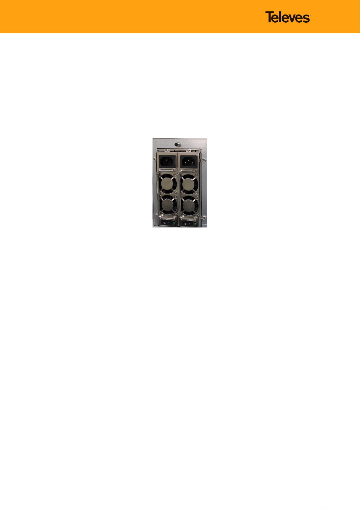
Powersupply......................................... 7
Redundant power supply (831011) . . . . . . . . . . . . . . . . . . . . . . . . . 7
Cabling ............................................ 7
Coaxial cabling . . . . . . . . . . . . . . . . . . . . . . . . . . . . . . . . . . . . 7
UTPcabling ...................................... 7
Network............................................ 8
2.1.4 Inputmodules ....................................... 8
2.1.5 IP output module . . . . . . . . . . . . . . . . . . . . . . . . . . . . . . . . . . . . . . 12
2.2 Installation examples . . . . . . . . . . . . . . . . . . . . . . . . . . . . . . . . . . . . . . . . 13
3 WEB Tool 14
3.1 Input Configuration......................................... 16
3.1.1 Digital TV . . . . . . . . . . . . . . . . . . . . . . . . . . . . . . . . . . . . . . . . . . 16
Modulestatus ........................................ 16
Digital Television tuning . . . . . . . . . . . . . . . . . . . . . . . . . . . . . . . . . . . 17
DVB-IP Streaming Reception . . . . . . . . . . . . . . . . . . . . . . . . . . . . 19
Tuned or configured channel streaming . . . . . . . . . . . . . . . . . . . . . . . . . . 20
3.1.2 Digital Video . . . . . . . . . . . . . . . . . . . . . . . . . . . . . . . . . . . . . . . . . 23
Digital Video reception . . . . . . . . . . . . . . . . . . . . . . . . . . . . . . . . . . . 23
3.1.3 DTV module status (Status) . . . . . . . . . . . . . . . . . . . . . . . . . . . . . . . . 24
3.1.4 CAMs............................................. 25
3.2 Output streaming (Outputs) . . . . . . . . . . . . . . . . . . . . . . . . . . . . . . . . . . . . 26
3.2.1 IP Streaming (IP) ...................................... 26
3.2.2 Status of the output streams coming from DTV inputs (DTV Monitoring) . . . . . . 28
3.2.3 Output bandwidth (Streaming bandwidth) . . . . . . . . . . . . . . . . . . . . . . . 29
3.3 Corporate Channel . . . . . . . . . . . . . . . . . . . . . . . . . . . . . . . . . . . . . . . . . 30
3.3.1 Videos............................................ 30
3.3.2 Channels .......................................... 31
3.4 System settings . . . . . . . . . . . . . . . . . . . . . . . . . . . . . . . . . . . . . . . . . . . 34
3.4.1 Account management (Account) . . . . . . . . . . . . . . . . . . . . . . . . . . . . . 34
3.4.2 Network configuration (Network) . . . . . . . . . . . . . . . . . . . . . . . . . . . . . 34
3.4.3 Date and time . . . . . . . . . . . . . . . . . . . . . . . . . . . . . . . . . . . . . . . . 36
3.4.4 Backup............................................ 37
i

HE-21: User Guide
3.4.5 Licenses........................................... 39
3.4.6 Shut down/Restart (Power Control) . . . . . . . . . . . . . . . . . . . . . . . . . . . . 40
3.5 SAPserver .............................................. 40
3.6 HTTP-to-UDP (UDP to HTTP) encapsulator . . . . . . . . . . . . . . . . . . . . . . . . . . . . 41
3.7 UPnPserver ............................................. 43
3.8 Webserver.............................................. 44
3.9 SNMP................................................. 45
3.10Logout ................................................ 46
ii

Document History and Modifications
Rev. No. Chapter Description of modification/changes
1.0 First review
1

HE-21: User Guide
1. Introduction
Arantia HE-21 Compact Headend - The smart choice for digital service reception.
Arantia HE-21 headend is the most efficient solution in the market for the reception and streaming of
IPTV channels, allowing operators, hospitality, corporations, airports, ports, transport stations, admin-
istrative buildings, and singular projects to distribute IPTV and Digital TV services (DVB-S/S2, DVB-T/T2,
DVB-C, ISDB-T, ATSC, etc.) with the highest quality and reliability.
It integrates all the functions into a single chassis, including a wide range of input interfaces, making
service aggregation easier for transport over any type of network in the most efficient way.
The equipment supports FTA (free-to-air) channels and pay TV services through the DVB CIinterfaces
included in some of the input modules.
In addition, Arantia HE-21 compact headend complies with the most common standards in the industry:
MPEG-2, MPEG-4 AVC/H.264, MPEG-H HEVC/H.265, SD/HD/4K, MP2, MP3, AAC, DD+, ...
1.1 Main features
•Content aggregation
When configured as a high-density receiver, the Arantia HE-21 headend allows the integration of
services from different sources, including IP, DVB-S/S2, DVB-C, DVB-T/T2, ATSC, ISDB-T and HDMI
with IP output.
•Central headend
The flexibility of system configuration allows for the aggregation of services from different sources
and for the preparation for the distribution over IPTV networks.
•Web Tool
The Arantia HE-21 headend configuration is based on web platform that optimizes the installation
procedure.
•Descrambling
The service is compatible with most CAs in the market that support the AES and DVB CSA algo-
rithms through the DVB CIinterfaces included in some input modules. It allows the descrambling
of multiple services, maximizing system use and solution design.
•Personalisation
Arantia HE-21 adapts to any project requirements, allowing for multiple configurations thanks to
the wide range of card types available.
•Designed to last
The Arantia HE-21 headend is manufactured using maximum quality components and equipped
with a forced cooling system that allows for a long service life.
•Prepared for the future
UHD television and the new HEVC codec are both compatible with the Arantia HE-21 headend.
2

1.2 Built-in applications
Some of the utilities included in Arantia HE-21 are described below.
WEB SERVER
The Web server application is an HTTP server embedded in the Arantia HE-21 headend. It
can serve static content like html web pages, documents, images, etc. Content can be easily
uploaded through the FTP server provided together with the Web server.
Application examples:
•Middleware hosting for hospitality systems.
•Hosting of a guest welcome screen.
•Photo gallery.
•Limited capacity music and video streaming.
•Firmware hosting for automatic updating of networked devices.
SAP ANNOUNCEMENTS
The SAP Server application is an integrated server that implements the service announce-
ment protocol in the Arantia HE-21 headend. It is used to announce IPTV services to net-
worked devices. Networked devices can automatically discover IPTV services. IPTV services
may be grouped into play lists to make organization of large channel lists easier.
Application examples:
•Automatic IPTV service detection
•Service bundles by subject
UPnP SERVER
The UPnP Server application is an Universal Plug and Play server embedded in the Arantia
HE-21 headend. It is used to announce IPTV services to networked devices. Networked de-
vices can automatically discover IPTV services. IPTV services may be grouped into containers
to make organization of large channel lists easier.
Application examples:
•Automatic IPTV service detection
•Service bundles by subject
•URL announcement.
UDP-to-HTTP PROXY
UDP-to-HTTP application is a multicast traffic relay embedded in the Arantia HE-21 headend.
It can resend the IPTV multicast traffic available in a network to HTTP clients upon request.
The application does not transcode the contents, so IPTV services reach the HTTP clients
with their original quality.
Application examples:
•IPTV over wireless networks.
•IPTV outside the LAN (extranets, Internet).
•IPTV in devices that do not support multicast.
1.3 Optional items
831119 - CORPORATE CHANNEL LICENSE
3

HE-21: User Guide
The corporate channel license provides the capability of including additional multicast chan-
nels besides those associated to the DVB inputs.
Supported codecs are MPEG 1/2/4, MJPEG, H.263 and H.264 for video and MPEG audio, AAC,
and AC3/A52 for audio.
Accepted containers: MPG, MPEG, TS, MP4, AVI, MKV, FLV, WMV, MOV, and PS
Available space for video storage: 150 GB.
830325 - ITV MDW LITE & ADMIN TV LICENSE
ITV MDW LITE & TV ADMIN is an optional application that extends Arantia HE-21 headend
functionality. It includes an IPTV lite middleware for the display of IPTV channels on LG TV
and Samsung TV devices. In addition, it provides an interface for remote device management
and control, as well as IPTV channel management.
The lite IPTV middleware allows the simultaneous connection of a virtually unlimited number
of users. Middleware’s style may be personalized. The middleware integration in the Arantia
HE-21 headend allows for the automatic synchronization between the middleware and the
headend channels, as well as the channel automatic discovery by means of the SAP service
announcement protocol.
The remote management and control tool for LG TV and Samsung TV devices allows the
performance of remote and automatic actions, such as switch on, volume, current input,
volume, firmware update, middleware configuration, etc.
1.4 Accessories
831311 - ARANTIA HE-21 RACK RAILS
Mounting system with sliding rails for HE-21, compatible with 19”racks.
4

2. The equipment
The equipment has been fully assembled and has successfully passed all of the quality tests in our
laboratory.
General information:
831010 - ARANTIA HE-21 4U CHASSIS
•19”rack mountable, 4RU
•Dimensions (mm): 176 x 430 x 470 (Height x Width x Depth)
•Input voltage: 100-240 VAC, 50/60 Hz
•Max. power consumption: 200 W
•Operating temperature: 0 ºC - 45 ºC
•Storage temperature: -10 ºC - 60 ºC
•Humidity: 10 % - 90 % (without condensation)
•Modular configuration with up to 7 positions for input modules
•Forced ventilation
831011 - ARANTIA HE-21 4U CHASSIS 2xPSU
•19”rack mountable, 4RU
•Dimensions (mm): 176 x 430 x 470 (Height x Width x Depth)
•Input voltage: 90 - 264 VAC, 50/60 Hz
•Max. power consumption: 200 W
•Redundant power supply
•Operating temperature: 0 ºC - 45 ºC
•Storage temperature: -10 ºC - 60 ºC
•Humidity: 10 % - 90 % (without condensation)
•Modular configuration with up to 7 positions for input modules
•Forced ventilation
831012 - ARANTIA HE-21 1U CHASSIS
•19”rack mountable, 1RU
5

HE-21: User Guide
•Dimensions (mm): 43 x 437 x 369 (Height x Width x Depth)
•Input voltage: 100 - 240 VAC, 50/60 Hz
•Max- power consumption: 180 W
•Operating temperature: 0 ºC - 45 ºC
•Storage temperature: -10 ºC - 60 ºC
•Humidity: 10 % - 90 % (without condensation)
•Modular configuration with one position for an input module
•Forced ventilation
2.1 Assembly and preliminary considerations
2.1.1 Connections and buttons
Fig. 1: Connections and buttons 831010
Fig. 2: Connections and buttons 831012
2.1.2 Rack installation
The headend can be secured to the rack by using the front support sockets, by fixing the equipment to
the vertical parts of the rack frame with 4 screws.
The reinforced and recommended fastening system for chassis 831010 and 831011 includes the instal-
lation of 2 side rails (831311 ARANTIA HE-21 Rack Rails) on the vertical parts of the frame and the fixing
of the equipment on those.
2.1.3 Basic connections
The basic connections for equipment commissioning are described below.
6

Power supply
To power the equipment, the power cord (IEC) provided shall be connected to the IEC C14 female con-
nector on the rear of the chassis.
Redundant power supply (831011)
If you purchased an HE-21 (831011), your equipment includes a redundant power supply; on the rear
side of the unit there are two connections. Once correctly connected, the LEDS at the bottom will turn
green.
Fig. 3: Redundant power supply
In case of error in any of the two units, the LED associated with it will turn red and the headend will
produce a warning beep sound. To cancel the beep sound, just push the button on the power supply
unit, as shown on the image above.
Cabling
For appropriate operation and to prevent any problems associated with the signal, it is advised that the
recommendations below regarding the HE-21 headend cabling are followed.
Coaxial cabling
Coaxial cabling should follow the recommendations below, the usual recommendations for coaxial ca-
bling:
•Minimum length: half-wave length multiplied by the cable’s speed factor
•Recommended length: use multiples of half wavelengths mutiplied by the cable’s speed
factor
•Minimum cable bending radius: 5 times the cable diameter.
Speed factor examples:
•214102 T-100plus Coaxial Cable => Speed factor: 0.82
•213002 T-200plus LSFH Coaxial Cable => Speed factor: 0.83
UTP cabling
UTP cabling should follow the usual recommendations, as described below:
7

HE-21: User Guide
•UTP data cable category 6 or higher (Recommended: 212302 UTP CAT-6 LSFH Data cable)
•Data connector (RJ45) category 6 or higher (Recommended: 209902 RJ45 UTP CAT-6 Data connec-
tor)
•Minimum cable bending radius: 5 times the cable diameter.
Network
Both network ports should be wired using certified class 6 or higher patch cords with RJ-45 connectors
(UTP cabling).
Port layout is as follows:
eth0 eth1
The eth0 port is meant for headend control, as explained in the Network configuration (Network) section
of this manual. This allows access to the management software either by connecting a computer to the
eth0 interface, or by connecting the equipment to a local network so that the management tool can be
accessed from any PC in that LAN (provided the headend IP address and password are known).
The eth1 port should be connected to the local network over which the IPTV content is to be transmitted.
It will be typically connected to a Layer 3 switch appropriately configured for the correct management
of multicast content.
2.1.4 Input modules
831110 - ARANTIA HE-21 DVB-S/S2 DUAL INPUT
•Input frequency range: 950 ~ 2150 MHz
•Required signal input level: -85 ~ -20 dBm
•Symbol rate range:
–DVB-S QPSK: 1 ~ 45 Mbaud/s
–DVB-S2 QPSK/8PSK: 1 ~ 45 Mbaud/s
•Compatible carrier’s range: ±10 MHz
•Compatible FEC rates:
–DVB-S2 CCM:
*QPSK: 1/2, 3/5, 2/3, 3/4, 4/5, 5/6, 8/9, 9/10
*8PSK: 3/5, 2/3, 3/4, 4/5, 5/6, 8/9, 9/10
–DVB-S
*QPSK: 1/2, 2/3, 3/4, 5/6, 7/8
•Compatible with DiSEqC support: 1.1
•Data Burst & Tone Burst compatible
•2 x 75Ω“F”female connectors
831111 - ARANTIA HE-21 DVB-S/S2 QUAD INPUT
•Input frequency range: 950 ~ 2150 MHz
•Required signal input level: -69 ~ -23 dBm
•Symbol rate range:
–DVB-S QPSK: 1 ~ 45 Mbaud/s
8

–DVB-S2 QPSK/8PSK: 1 ~ 45 Mbaud/s
•Compatible carrier’s range: ±10 MHz
•Compatible FEC rates:
–DVB-S2 CCM:
*QPSK: 1/4, 1/3, 2/5, 1/2, 3/5, 2/3, 3/4, 4/5, 5/6, 8/9, 9/10
*8PSK: 3/5, 2/3, 3/4, 5/6, 8/9, 9/10
–DVB-S
*QPSK: 1/2, 2/3, 3/4, 5/6, 7/8
•Compatible with DiSEqC support: 1.1
•Data Burst & Tone Burst compatible
•2 x 75Ω“F”female connectors
831115 - ARANTIA HE-21 DVB-T/T2 DUAL INPUT
•Input frequency range: VHF and UHF
•Required signal input level: -65 ~ -20 dBm
•Compatible modulations: QPSK, 16QAM, 64QAM, 256QAM
•Compatible bandwidths: 6, 7, 8 MHz
•Compatible FFT modes: 1K, 2K, 4K, 8K, 16K, 32K
•Compatible FEC rates: 1/2, 3/5, 2/3, 3/4, 4/5, 5/6, 7/8
•Compatible guard intervals: 1/4, 1/8, 1/16, 1/32, 1/64, 1/128, 19/128, 19/256
•PLP (Physical Layer Pipe) compatible
•High-sensitivity DVB-T2 tuner
•75Ω“F”input female connector
•75-Ω“F”output female connector
831114 - ARANTIA HE-21 DVB-T/T2 QUAD INPUT
•Input frequency range: VHF and UHF
•Required signal input level: -65 ~ -20 dBm
•Compatible modulations: QPSK, 16QAM, 64QAM, 256QAM
•Compatible bandwidths: 6, 7, 8 MHz
•Compatible FFT modes: 1K, 2K, 4K, 8K, 16K, 32K
•Compatible FEC rates: 1/2, 3/5, 2/3, 3/4, 4/5, 5/6, 7/8
•Compatible guard intervals: 1/4, 1/8, 1/16, 1/32, 1/64, 1/128, 19/128, 19/256
•PLP (Physical Layer Pipe) compatible
•High-sensitivity DVB-T2 tuner
•75Ω“F”input female connector
•75-Ω“F”output female connector
831123 - ARANTIA HE-21 DVB-S2/T2/C/ISDB-T CIDUAL INPUT
•Required signal input level: -63 ~ -30 dBm
•ISDB-T
–Bandwidth: 6, 7, 8 MHz
9

HE-21: User Guide
–COFDM demodulator and FEC decoding
•DVB-T/T2
–Input frequency range: VHF and UHF
–Compatible modulations: QPSK, 16QAM, 64QAM, 256QAM
–Compatible bandwidths: 1.7, 5, 6, 7, 8 MHz
–Compatible FFT modes: 1K, 2K, 4K, 8K, 16K, 32K
–Compatible FEC rates: 1/2, 2/3, 3/4, 5/6, 7/8
–Compatible guard intervals: 1/4, 1/8, 1/16, 1/32, 1/64, 1/128, 19/128, 19/256
–PLP (Physical Layer Pipe) compatible
•DVB-C/C2
–Compliant with DVB-C specifications (ITU-T J.83 Annexes A/B/C)
–Compatible demodulation range:
*QAM: 16QAM ~ 256 QAM
*DVB-C2 COFDM: 16QAM ~ 4096QAM
–Compatible bandwidths: 6, 7, 8 MHz
–FEC LDPC/BCH compatible
•DVB-S/S2
–Input frequency range: 950 ~ 2150 MHz
–Symbol rate range:
*DVB-S QPSK: 1 ~ 45 Mbaud/s
*DVB-S2 QPSK/8PSK: 1 ~ 45 Mbaud/s
–Compatible carrier’s range: ±10 MHz
–Compatible FEC rates:
*DVB-S2 CCM:
· QPSK: 1/2, 3/5, 2/3, 3/4, 4/5, 5/6, 8/9, 9/10
· 8PSK: 3/5, 2/3, 3/4, 5/6, 8/9, 9/10
*DVB-S
· QPSK: 1/2, 3/5, 2/3, 3/4, 4/5, 5/6, 8/9, 9/10
–Compatible with DiSEqC support: 1.1
–Data Burst & Tone Burst compatible
•Dual CIslot
•2 x 75Ω“F”female connectors
831121 - ARANTIA HE-21 ATSC QUAD INPUT
•Required signal input level: -63 ~ -20 dBm
•Compatible bandwidths 6, 7, 8 MHz
•Input frequency range: 44 MHz ~ 1002 MHz
•Compatible demodulations:
–8VSB with integrated FEC function (American ATSC compliant).
–64QAM and 256QAM (OpenCable specifications compliant).
10

•75Ω“F”input female connector
•75-Ω“F”output female connector
831118 - ARANTIA HE-21 DVB-IPINPUT
•Compatible with networks: 10/100/1000BaseT
•Compatible with UDP/RTP Multicast IPv4 reception
•Maximum data input rate: 500 Mbit/s
•Connector: RJ45
Note: Maximum supported cards of this type per chassis: 1
831122 - ARANTIA HE-21 HDMIQUAD INPUT
•Compatible colour spaces: YV12, NV12, YUY2, RGB24, RGB32
•Compatible input resolutions:
–HD:
*1920×1080p 60/50/30/25/24fps
*1920×1080i 60/50fps
*1280×720p 60/50fps
*1280×1024p 60fps
*1280×960p 60fps
*1024×768p 60fps
–SD
*800×600p 60fps
*640×480p 60fps
*720×480p 60fps
*720×576p 50fps
*720×480i 60fps
*720×576i 50fps
•Audio and video input: 4 × HDMI
•Video output: MPEG-4 AVC/H.264
•Audio output: Stereo AC-3
•4 HDMIConnectors
Note: Maximum supported cards of this type per chassis: 1
831124 - ARANTIA HE-21 SDIQUAD INPUT
–Compatible colour spaces: YV12, NV12, YUY2, RGB24, RGB32
–Compatible input resolutions:
*3G-SDI(SMPTE 424M):
· 1920×1080p 60/50fps
*HD-SDI(SMPTE 292M):
11

HE-21: User Guide
· 1920×1080p 30/25/24fps
· 1920×1080i 60/50fps
· 1280×720p 60/50fps
*SD-SDI(SMPTE 259M):
· 720×480i 60fps
· 720×576i 50fps
–Compatible output resolutions:
*HD:
· 1920×1080p 30/25/24fps
· 1920×1080i 60/50fps
· 1280×720p 60/50fps
*SD:
· 720×480i 60fps
· 720×576i 50fps
–Audio and video input: 4 × SDI
–Video output: MPEG-4 AVC/H.264
–Audio output: Stereo AC-3
–4 BNC Connectors
Note: Maximum supported cards of this type per chassis: 1
2.1.5 IP output module
•2x 10/100/1000BaseT Ethernet (RJ45)
–1x Administration
–1x IPTV streaming
•Supports UDP/RTP Multicast/Unicast IPv4/IPv6 transmission
•Supports SPTS and MPTS (full multiplex)
•Data streaming rate up to 500 Mbit/s
•Transport stream, MPEG-2, MPEG-4 AVC/H.264, MPEG-H HEVC/H.265, SD/HD/4K, MP2, MP3, AAC,
DD+, . . .
•PIDfiltering
•EIT, SDT, and DTT table EPG Pass-through
•SNMP
The rear side of the headend holds the input boards, where the appropriate antenna appropiate signals
need to be be connectedappropiate signals need to be be connected.
12

2.2 Installation examples
The following diagram shows the different input service sources supported by HE-21.
Fig. 4: Installation examples
•The DTV inputs allow the reception of DVB-S/S2, DVB-T/T2, DVB-C, ISDB-T, etc.
•The IPTV input allows the reception of MPTS from an IPTV operator.
•The HDMIinput allows the reception of audio/video from HDMIsources like encoders, PCs, etc.
13

HE-21: User Guide
3. WEB Tool
Given that it is a web-based tool, it will be accessed using a web browser (Google Chrome recom-
mended) together with the URL provided by the system administrator, identical with the IP assigned
to the headend.
Note: The default IP address to access the administration tool is http://192.168.1.10
The web tool will remain blocked until the booting and initialization process of the headend has been
completed.
Fig. 1: System boot
To avoid non-authorized user access, access to the application will require a user and a password.
Note: The authentication default values are:
•User: arantia
•Password: headend
Fig. 2: System login
Once you have logged in, the main application interface is displayed. Its operation is described below.
Fig. 3: Welcome screen
14

Menu
The left column shows the navigation menu; clicking on each entry will display the sub-menus, if any.
The menu structure is described below:
•Inputs
–Digital TV
–Status
–CAMs
–Digital Video
•Outputs
–IP List
–Digital Television channel monitoring (DTV Monitoring)
–Streaming bandwidth
•Corporate Channel
–Channels
–Videos
•System Settings
–User Account
–Network
–Date and Time
–Backup
–Licenses
–Power supply
•SAP server
•UDP to HTTP
•UPnP server
•Web server
•ITV MDW Lite
•Logout
Available cards (Input Modules)
The central box includes a table with the description of the input models that are plugged
in and detected by the system. For each, the order of the module in the chassis is also
specified.
Note: The cards are numbered from left to right, looking from the rear of the headend.
Uptime
Information regarding the equipment uptime is displayed right under the table mentioned
above.
15

HE-21: User Guide
3.1 Input Configuration
The configuration procedure for the different input modules supported by the HE-21 headend is de-
scribed below.
3.1.1 Digital TV
This section shows a list with the links to the configurations of all the tuners in each module.
Fig. 4: DTV input list
Module status
The specific configuration of each tuner may be displayed by clicking on the desired input.
The information provided by HE-21 both for an unconfigured DVB-T/T2 module (left-hand side) and for
a configured and tuned module (right-hand side) is described below.
Fig. 5: DVB-T2 module status (left: not configured, right: configured)
In case of an unconfigured module, the tool provides information relative to the last configuration used
for the selected module.
For a tuned module, the tool provides information relative to the configuration set for the selected mod-
ule, as well as the list of channels being received, which could be individually configured for streaming.
Some information about the status of the signal at the demodulator input (frontend) is also provided.
The values are:
16

•Has Lock (True/False): Tuning status.
•Bit Error Rate: The number of errors in the tuned signal during the analysis period.
•Signal Strength (dBuV): Measure of the power received at the module’s demodulator. (It doesn’t
necessarily have to match the level measured at the antenna cable connector)
•SNR (signal-to-noise ratio) (dBuV): Signal-to-noise ratio evaluated at the module’s demodulator. (It
doesn’t necessarily have to match the level measured at the antenna cable connector)
Note: In case the headend is not able to tune a given channel, and after reviewing the information
entered in the web tool, it is recommended that the status of the signal at the headend’s input is checked
with the help of a field strength meter (BER, MER and PW).
Note: The bit error rate has to be zero for the time interval being analysed. A rate over ten would
indicate a deficient signal.
Digital Television tuning
Upon accessing the status of a module, a configuration button is found (Configure) that allows access to
its tuning parameters. In case the module is active, all the services provided by the module will stop. To
prevent accidental access to parameter configuration, a confirmation dialogue window will display for
the action to be confirmed.
Fig. 6: Module configuration dialogue
•Description of tuning parameters
–Enable module
This selector allows a module to be enabled and the tuning process to start, or else to keep
the module disabled and just store the information that was entered.
–SID change revision (Check SID time)
This field allows the SID update (upon change) based on the service name. This should never
take place, since any SID modification would mean a new service. However, particular be-
haviours have been detected regarding some operators who change the SID without it nec-
essarily meaning a new service: the service is the same, since the service name is retained.
The revision may be configured for different time intervals: 5 m, 30 m, 1 h, 3 h, or 1 day.
Note: This function is disabled by default
17
This manual suits for next models
3
Table of contents
Popular Chassis manuals by other brands

National Instruments
National Instruments NI cDAQ-9188 SAFETY, ENVIRONMENTAL, AND REGULATORY INFORMATION

Supermicro
Supermicro SC826E1-R800LP user manual

Streacom
Streacom FC5 evo user guide

Dynex
Dynex MidTower user guide

Supero
Supero Supero SC512 Series user guide

TRENDnet
TRENDnet TEG-S3000I - TEG Gigabit Layer 2 Managed Chassis S3000i... Specifications