manuals.online logo
Brands
  1. Home
  2. •
  3. Brands
  4. •
  5. Telex
  6. •
  7. Intercom System
  8. •
  9. Telex RadioCom TR-700 Technical manual

Telex RadioCom TR-700 Technical manual

MENU
SET
MIC
PT
TX
PT
TALK
6
7
89
MENU
SET
MIC
PT
TX
PT
TALK
2
1
3
4
5
TR-700 Quick Start Card
Initial Beltpack and Base Station Set-up
1. Press [MENU] as powering-up the base station. This will place it on group 01A and set
the receives on channels: 01, 02 , 03 and 04. Ensure the appropriate portable station
connect path is enabled. If used stand alone, the base should be in the 4-wire mode.
2. Set beltpack back panel slide switch to push-to-talk (PT TALK).
3. Press [MENU] as powering-up the beltpack. This will place the beltpack on group
01A with channel 01 flashing.
4. Use the [UP] and [DOWN] arrow buttons to change the channel to an unoccupied receive
channel on the base station. Then press [SET]. Press [MENU] if not changing channels.
5. The group/channel on the beltpack should now match the group and a receive channel
on the base station. Nothing should be flashing on the beltpack screen.
6. Plug a headset into the beltpack and set the microphone gain so the BAT/OM light
flashes at the beginning of most words at normal speech levels.
Special Functions
ClearScan·······Press [MENU]+[SET] buttons for 3 seconds. After 25 seconds of
searching, the beltpack will produce a list of the groups organized
from best (clearest) to worse. The best group is displayed
flashing. Use the [UP] and [DOWN] buttons to select other
groups if desired.
Lockout ········Press [UP]+[DOWN] arrows buttons for 3 seconds. Repeat to
toggle it off/on.
1st Use Default · · · Press [MENU] as powering-up the beltpack. Sets beltpack on
group 01A with channel 01 flashing. User must then set the
channel. All user-programmed memory is retained.
Factory Default · · Press [MENU]+[SET]+[UP]+[DOWN] buttons for 3 seconds to
software “reset” the beltpack. All user-programmed memory is erased.
Talk Latch Enable/Disable
Talk Button ................Press and hold [SET] then press [TALK] to enable
latching or non-latching.
1. [MENU] and [SET] buttons – Used to select menus and set options on the LCD.
2. LCD display.
3. [UP] and [DOWN] buttons – Used to select beltpack options on the LCD.
4. Microphone Gain – Adjusts the headset’s microphone gain. Adjust so that the light
flashes at the beginning of most words at normal speech levels.
5. Push-to-Talk/Push-to-Transmit Switch –
Push-to-Talk (PT TALK) – The transmitter is always on. No audio sent
unless the talk button is pressed. Recommended position.
Push-to-Transmit (PT TX) - The transmitter and audio path are off except
when the talk button is pressed.
6. Headset Connector – Male XLR connector for Telex units, Female XLR connector
for RTS units.
7. Battery Latch – Press down to enable the battery pack to be released. While the latch
is held down, slide the battery pack about 1/8 inch back, toward the latch, until it stops,
then lift out.
8. Receive Antenna – Screw type ¼ wave replaceable antenna. The receiver antenna is
always the longer antenna. Color dot on the screw end of the antenna must match color
dot on antenna receptacle.
9. Transmit Antenna – Screw type ¼ wave replaceable antenna. Color dot on the screw
end of the antenna must match color dot on antenna receptacle.
MENU
SET
MIC
PT
TX
PT
TALK
6
7
89
MENU
SET
MIC
PT
TX
PT
TALK
2
1
3
4
5
TR-700 Quick Start Card
Initial Beltpack and Base Station Set-up
1. Press [MENU] as powering-up the base station. This will place it on group 01A and set
the receives on channels: 01, 02 , 03 and 04. Ensure the appropriate portable station
connect path is enabled. If used stand alone, the base should be in the 4-wire mode.
2. Set beltpack back panel slide switch to push-to-talk (PT TALK).
3. Press [MENU] as powering-up the beltpack. This will place the beltpack on group
01A with channel 01 flashing.
4. Use the [UP] and [DOWN] arrow buttons to change the channel to an unoccupied receive
channel on the base station. Then press [SET]. Press [MENU] if not changing channels.
5. The group/channel on the beltpack should now match the group and a receive channel
on the base station. Nothing should be flashing on the beltpack screen.
6. Plug a headset into the beltpack and set the microphone gain so the BAT/OM light
flashes at the beginning of most words at normal speech levels.
Special Functions
ClearScan·······Press [MENU]+[SET] buttons for 3 seconds. After 25 seconds of
searching, the beltpack will produce a list of the groups organized
from best (clearest) to worse. The best group is displayed
flashing. Use the [UP] and [DOWN] buttons to select other
groups if desired.
Lockout ········Press [UP]+[DOWN] arrows buttons for 3 seconds. Repeat to
toggle it off/on.
1st Use Default · · · Press [MENU] as powering-up the beltpack. Sets beltpack on
group 01A with channel 01 flashing. User must then set the
channel. All user-programmed memory is retained.
Factory Default · · Press [MENU]+[SET]+[UP]+[DOWN] buttons for 3 seconds to
software “reset” the beltpack. All user-programmed memory is erased.
Talk Latch Enable/Disable
Talk Button ................Press and hold [SET] then press [TALK] to enable
latching or non-latching.
1. [MENU] and [SET] buttons – Used to select menus and set options on the LCD.
2. LCD display.
3. [UP] and [DOWN] buttons – Used to select beltpack options on the LCD.
4. Microphone Gain – Adjusts the headset’s microphone gain. Adjust so that the light
flashes at the beginning of most words at normal speech levels.
5. Push-to-Talk/Push-to-Transmit Switch –
Push-to-Talk (PT TALK) – The transmitter is always on. No audio sent
unless the talk button is pressed. Recommended position.
Push-to-Transmit (PT TX) - The transmitter and audio path are off except
when the talk button is pressed.
6. Headset Connector – Male XLR connector for Telex units, Female XLR connector
for RTS units.
7. Battery Latch – Press down to enable the battery pack to be released. While the latch
is held down, slide the battery pack about 1/8 inch back, toward the latch, until it stops,
then lift out.
8. Receive Antenna – Screw type ¼ wave replaceable antenna. The receiver antenna is
always the longer antenna. Color dot on the screw end of the antenna must match color
dot on antenna receptacle.
9. Transmit Antenna – Screw type ¼ wave replaceable antenna. Color dot on the screw
end of the antenna must match color dot on antenna receptacle.
1. On/Off & Volume Control - Turns the beltpack power on and controls headset
volume.
2. Bat/Overmod Light - LED will flash once when unit is turned on if the battery
is good. If the light stays on, battery is low. If the light does not flash, battery is
dead. A normal mic gain setting will cause the LED to flash at the beginning of
most words at normal speech levels. If the gain is too large, the LED will be red
during the complete word at normal speech levels.
3. Talk Light - LED is on when the talk button is active.
4. Talk button - Press to enable the audio path from the headset. “TALK” LED,
#3, will turn red when enabled. A quick press and release latches button on,
unless latching has been disabled in software. Holding the button for over 1/2 a
second will cause the audio path to be enabled only for as long as the button is
held.
VOL
OFF
Telex R
BAT/OM TALK
TALK
12
4
3
VOL
OFF
Telex R
BAT/OM TALK
TALK
12
4
3
Battery Installation
Ensure that the On/Off volume control knob is turned off.
Press and hold down the battery release latch, slide the battery
pack about 1/8 inch back, toward the latch, until it stops.
Then lift battery pack out. Replace batteries as follows:
5. Be sure strap goes under batteries.
2. Pull battery strap to remove low
or dead batteries.
Battery Installation
Ensure that the On/Off volume control knob is turned off.
Press and hold down the battery release latch, slide the battery
pack about 1/8 inch back, toward the latch, until it stops.
Then lift battery pack out. Replace batteries as follows:
3. Load new batteries following the
polarity as shown in battery case
1. Open the battery pack by inserting
finger nail and lifting.
4. Start loading at the end of the case where
the strap is attached to the case.
6. Tuck end of strap under door
when placing the battery cover
back on the case.
5. Be sure strap goes under batteries.
803448-1
Feb 2002
Battery Installation
Ensure that the On/Off volume control knob is turned off.
Press and hold down the battery release latch, slide the battery
pack about 1/8 inch back, toward the latch, until it stops.
Then lift battery pack out. Replace batteries as follows:
5. Be sure strap goes under batteries.
2. Pull battery strap to remove low
or dead batteries.
Battery Installation
Ensure that the On/Off volume control knob is turned off.
Press and hold down the battery release latch, slide the battery
pack about 1/8 inch back, toward the latch, until it stops.
Then lift battery pack out. Replace batteries as follows:
3. Load new batteries following the
polarity as shown in battery case
1. Open the battery pack by inserting
finger nail and lifting.
4. Start loading at the end of the case where
the strap is attached to the case.
6. Tuck end of strap under door
when placing the battery cover
back on the case.
5. Be sure strap goes under batteries.
803448-1
Feb 2002
WARNING
Do not place an alkaline
TR battery pack in any
battery charger. Severe
charger and battery pack
damage may result.
WARNING
Do not place an alkaline
TR battery pack in any
battery charger. Severe
charger and battery pack
damage may result.

Other Telex Intercom System manuals

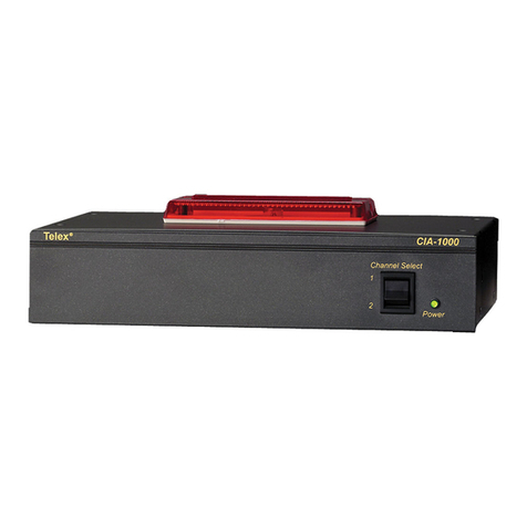
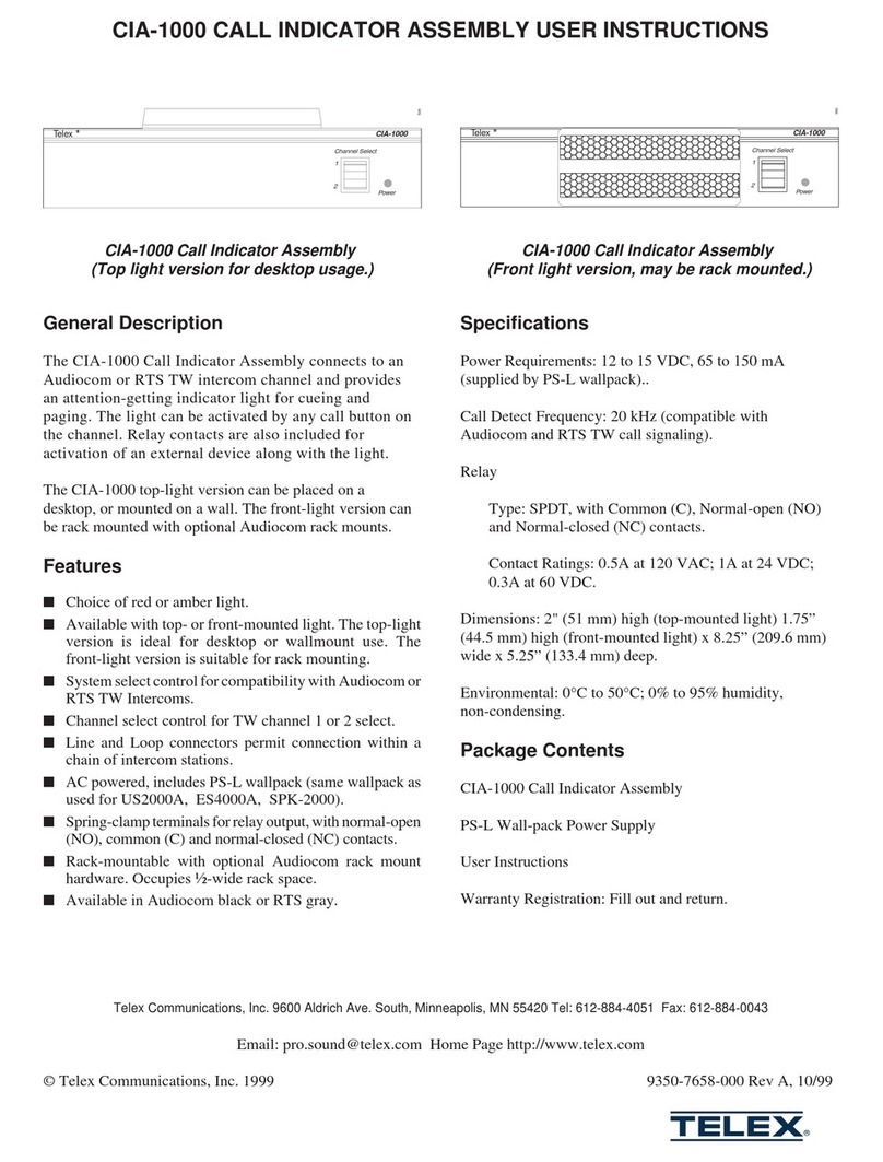
Telex CIA-1000 User manual

Telex

Telex CIA-1000 User manual

Telex RadioCom BTR-300 Administrator guide

Telex

Telex RadioCom BTR-300 Administrator guide

Telex Legacy XO-1 User manual

Telex

Telex Legacy XO-1 User manual

Telex IC-1 User manual

Telex

Telex IC-1 User manual

Telex Audiocom BP-2002 User manual

Telex

Telex Audiocom BP-2002 User manual

Telex Audiocom IFB-1000 User manual

Telex

Telex Audiocom IFB-1000 User manual

Telex RKP-4 Technical manual

Telex

Telex RKP-4 Technical manual

Telex RadioCom BTR-500/600C User manual

Telex

Telex RadioCom BTR-500/600C User manual

Telex RTS SPK300L User manual

Telex

Telex RTS SPK300L User manual

Telex Audiocom WM1000 Installation and operating instructions

Telex

Telex Audiocom WM1000 Installation and operating instructions

Telex Audiocom US-2002 User manual

Telex

Telex Audiocom US-2002 User manual

Telex 4030 User manual

Telex

Telex 4030 User manual

Telex BP-325 User manual

Telex

Telex BP-325 User manual

Telex 4012 Quick start guide

Telex

Telex 4012 Quick start guide

Telex Audiocom SPS-2000 User manual

Telex

Telex Audiocom SPS-2000 User manual

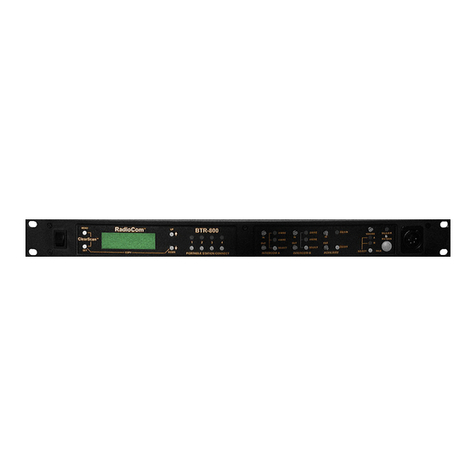
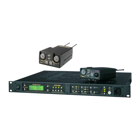
Telex RadioCom BTR-800 User manual

Telex

Telex RadioCom BTR-800 User manual

Telex SS2000 User manual

Telex

Telex SS2000 User manual

Telex Audiocom SS-2002 User manual

Telex

Telex Audiocom SS-2002 User manual

Telex RadioCom TR-200 User manual

Telex

Telex RadioCom TR-200 User manual

Telex RadioCom BTR-200 II User manual

Telex

Telex RadioCom BTR-200 II User manual

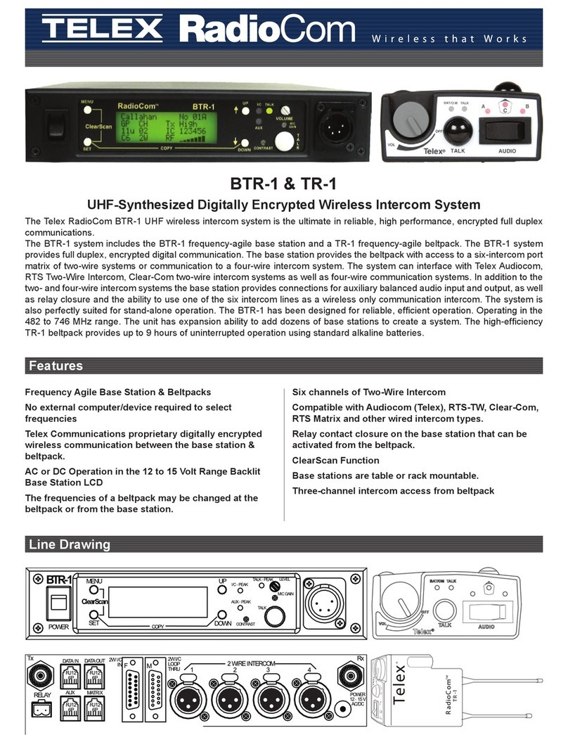
Telex RADIOCOM TR-1 User manual

Telex

Telex RADIOCOM TR-1 User manual

Telex IC-S User manual

Telex

Telex IC-S User manual

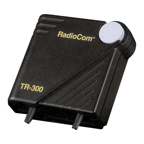
Telex RadioCom TR-300 User manual

Telex

Telex RadioCom TR-300 User manual

Telex RadioCom BTR-800 User manual

Telex

Telex RadioCom BTR-800 User manual

Popular Intercom System manuals by other brands

Bticino 344682 quick start guide

Bticino

Bticino 344682 quick start guide

RTS ODIN manual

RTS

RTS ODIN manual

Fermax iloft quick start guide

Fermax

Fermax iloft quick start guide

urmet domus 1717 Booklet

urmet domus

urmet domus 1717 Booklet

Mobotix T24 System manual

Mobotix

Mobotix T24 System manual

SSS Siedle AS-Ta-64/1 System manual

SSS Siedle

SSS Siedle AS-Ta-64/1 System manual

Fermax VDS Cityline Installer manual

Fermax

Fermax VDS Cityline Installer manual

Akuvox R20A quick guide

Akuvox

Akuvox R20A quick guide

Aiphone TC-ME user guide

Aiphone

Aiphone TC-ME user guide

urmet domus iPer Voice Max 1717 Series Complete user's manual

urmet domus

urmet domus iPer Voice Max 1717 Series Complete user's manual

Steren Platinum Series instruction manual

Steren

Steren Platinum Series instruction manual

ESP Enterview 5 instructions

ESP

ESP Enterview 5 instructions

Dnake 905D-Y4 user manual

Dnake

Dnake 905D-Y4 user manual

LEGRAND IS-0387 Instruction/installation sheet

LEGRAND

LEGRAND IS-0387 Instruction/installation sheet

DoorBird D11 Series installation manual

DoorBird

DoorBird D11 Series installation manual

HOLOVISION 404-W-VoIP installation instructions

HOLOVISION

HOLOVISION 404-W-VoIP installation instructions

Somogyi home DPV instruction manual

Somogyi

Somogyi home DPV instruction manual

Viking X-35-SS-EWP product manual

Viking

Viking X-35-SS-EWP product manual

manuals.online logo
manuals.online logoBrands
  • About & Mission
  • Contact us
  • Privacy Policy
  • Terms and Conditions

Copyright 2025 Manuals.Online. All Rights Reserved.