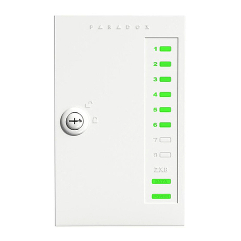
Telguard TG-PEM User manual

COMPANY CONFIDENTIAL
For use by TELGUARD®customers only.
Distribution to other parties strictly prohibited.
September 20, 2019
Telguard TG-PEM
Power & Expansion Module
Installation Manual

56051701 –Rev A i © 2019 Telguard
Important Note
Use our dealer site at www.telguard.com to configure the Telguard Power and Expansion Module (TG-PEM).
Foreword
Dealers purchase Telguard® cellular communicators for the quality, features and total value they represent. The Telguard
TG-PEM model is UL and ULC Listed for Commercial Fire and Commercial Burglary systems.
Technical Support
Technical support for all Telguard products is available:
Monday -Saturday 8am -8pm ET
Toll Free: 800-229-2326, option 9
About this Manual
This manual assumes that you have basic security system installation skills such as measuring voltages, stripping wire,
properly connecting wires together, connecting wires to terminals, and checking phone lines. It also assumes that you
have a familiarity with the proper installation and programming tasks related to various alarm panels.
The material and instructions covered in this manual have been carefully checked for accuracy and are presumed to be
reliable. However, Telguard assumes no responsibility for inaccuracies and reserves the right to modify and revise this
manual without notice.
It is our goal at Telguard to always supply accurate and reliable documentation. If a discrepancy is found in this
documentation, please mail or fax a photocopy of the corrected material to:
Telguard Technical Services
3225 Cumberland Blvd
Suite 300
Atlanta, GA USA 30339
Fax: 678-945-1651

56051701 –Rev A ii © 2019 Telguard
Repair and Warranty
If trouble is experienced with the Telguard Power and Expansion Module please contact Telguard
Technical Support for trouble shooting, repair and (or) warranty information. The dealer or end user
should not attempt any repair to the TelguardPower and Expansion Module. Repair of this equipment
should only be referred to qualified technical personnel.
Telguard will repair or replace (our option) inoperative units for up to two years from date of
manufacture. This excludes damage due to lightning or installer error. Unauthorized modifications void
this warranty. Not responsible for incidental or consequential damages. Liability is limited to price of
unit. This is the exclusive warranty and no other warranties will be honored, whether expressed or
implied.
An RMA must be assigned before returning product. You may obtain an RMA via phone at 800-229-2326
Note: RMA number must be on the outside of box or product will not be accepted.
Future Testing and Limitations on Use
The Telguard TG-PEM Series is part of an advanced design alarm communication system. It does not
offer guaranteed protection against burglary and fire. Any alarm communication system is subject to
compromise or failure.
The Telguard unit will not work without power. Electrically powered devices will not work if the power
supply is off for any reason, however briefly.
The cellular radio network, needed to transmit alarm signals from protected premises to a central
monitoring station, may be inoperable or temporarily out of service. Cellular radio networks are also
subject to compromise by sophisticated methods of attack.
This equipment, like any other electrical device, is subject to component failure. Although this
equipment is designed to be long lasting, the electrical components could fail at any time.
Due to these limitations, we recommend that if the automatic self-test feature of the Telguard system is
not enabled, other arrangements be made with the user to test the system at least once every three
months. Moreover, arrangements should also be made for on-site inspection/test by a licensed alarm
installer at least once each year.
Terms and Conditions for Use of Telguard Product
These Terms and Conditions are a legal contract between you and Telguard for the title to and use of the
Product. BY RETAINING AND USING THE PRODUCT YOU AGREE TO THE TERMS AND CONDITIONS
INCLUDING WARRANTY DISCLAIMERS, LIMITATIONS OF LIABILITY AND INDEMNIFICATION PROVISIONS
BELOW. IF YOU DO NOT AGREE TO THE TERMS AND CONDITIONS, DO NOT USE THE PRODUCT AND
IMMEDIATELY RETURN THE UNUSED PRODUCT FOR A COMPLETE REFUND. You agree to accept sole
responsibility for any misuse of the Product by you; and, in addition, any negligent or illegal act or
omission of you or your agents, contractors, servants, employees, or other users of the Product so long as
the Product was obtained from you, in the use and operation of the Product.

56051701 –Rev A iii © 2019 Telguard
INDEMNIFICATION OF TELGUARD
YOU SHALL INDEMNIFY, DEFEND AND HOLD HARMLESS TELGUARD FOR ANY OF THE COST, INCLUDING REASONABLE
ATTORNEYS’ FEES, AND FROM CLAIMS ARISING OUT OF YOU, YOUR CLIENTS’ OR OTHER THIRD PARTIES’ USE OR
OPERATION OF THE PRODUCT: (i) FOR MISUSE OR IN A MANNER NOT CONTEMPLATED BY YOU AND TELGUARD OR
INCONSISTENT WITH THE PROVISIONS OF THIS MANUAL; (ii) IN AN ILLEGAL MANNER OR AGAINST PUBLIC POLICY; (iii) IN
A MANNER SPECIFICALLY UNAUTHORIZED IN THIS MANUAL; (iv) IN A MANNER HARMFUL OR DANGEROUS TO THIRD
PARTIES; (v) FROM CLAIMS BY ANYONE RESPECTING PROBLEMS, ERRORS OR MISTAKES OF THE PRODUCT; OR (vi)
COMBINATION OF THE PRODUCT WITH MATERIAL, MODIFICATION OF THE PRODUCT OR USE OF THE PRODUCT IN AN
ENVIRONMENT NOT PROVIDED, OR PERMITTED, BY TELGUARD IN WRITING. THE PARTIES SHALL GIVE EACH OTHER
PROMPT NOTICE OF ANY SUCH COST OR CLAIMS AND COOPERATE, EACH WITH THE OTHER, TO EFFECTUATE THIS
INDEMNIFICATION, DEFENSE AND HOLD HARMLESS.
WARRANTY and LIMITATIONS
TELGUARD WILL REPAIR OR REPLACE (OUR OPTION) INOPERATIVE UNITS FOR UP TO TWO YEARS FROM DATE OF
MANUFACTURE. EXCLUDES DAMAGE DUE TO LIGHTNING OR INSTALLER ERROR AS WELL AS UNITS THAT INCORPORATE
MATERIAL, OR USED IN A MANNER OR ENVIRONMENT, NOT SPECIFICALLY AUTHORIZED IN THIS MANUAL.
UNAUTHORIZED MODIFICATIONS VOID THIS WARRANTY. NOT RESPONSIBLE FOR INCIDENTAL OR CONSEQUENTIAL
DAMAGES. LIABILITY LIMITED TO PRICE OF UNIT. THIS IS THE EXCLUSIVE WARRANTY, IN LIEU OF ALL OTHER
WARRANTIES INCLUDING IMPLIED WARRANTIES OF MERCHANTABILITY, TITLE, DELIVERY, INFRINGEMENT OR FITNESS
FOR A PARTICULAR PURPOSE AND NO OTHER WARRANTIES WILL BE HONORED, WHETHER EXPRESSED OR IMPLIED.

56051701 –Rev A iv © 2019 Telguard
Table of Contents
Important Note i
Foreword i
Table of Contents iv
General Description and Operation 1
Features 2
Operating Modes 2
Power from Panel 2
Dry Inputs 2
Alarm Format Support 3
Remote Operational Status 4
Programmable Supervisory Trip Output (STC1) Relay 4
Programmable Supervisory Trip Output (STC2) Relay 4
LEDs 4
Getting Ready 5
Pre-Installation Checklist 5
Installation 6
Summary 6
Step 1: Register the TG-7 or TG-7FS Communicator 6
Step 2: Pre-configure the TG-PEM prior to installation 6
Step 3: Mount the TG-7 or TG-7FS Communicator 6
Step 4: Mount the TG-PEM 7
Step 5: Connect the TG-PEM to the TG-7 or TG-7FS Host 8
Step 6: Power Up and Configure 8
Step 7: Connect Zone Inputs (if using) 9
Check Proper Operation of Zones 9
Optional: Connect supervisory trip output 10
Complete the Telguard Power and Expansion Module Installation 10
Appendix 1 –Installing a Second TG-PEM 11
Mounting Bracket 11
Installing Circuit Board 12

56051701 –Rev A v © 2019 Telguard
Wiring Connections 12
Appendix 2 –Connection Guide 13
Single TG-PEM System 13
Two TG-PEM System 13
Wiring Diagrams 14
Main Terminal Strip Pin Assignments 15
DC Terminal Strip Pin Assignments 16
Wire Lengths 16
End of Line Resistors 16
Appendix 3 –Troubleshooting Guide 17
LED Indicator Guide 17
Appendix 4 –Power Specifications 18
Power consumption 18

56051701 –Rev A 1 © 2019 Telguard
General Description and Operation
The TelguardTG-PEM is an accessory for the Telguard TG-7FS fire communicator model and the TG-7 burglary
communicator model used to provide DC-to-DC power conversion and/or expand the number of zone inputs.
The TG-PEM will accept DC power from the panel auxiliary output and convert to the proper DC voltage required to power
itself, the TG-7 Series communicator and a second TG-PEM (if equipped). Powering from the panel eliminates the need for
the communicator’s external power supply and the backup battery within the metal enclosure.
The TG-PEM has 8 dry contact inputs that may be configured as normally open, normally closed or supervised zone. Each
zone can be configured independently as needed for your application.
Note: The TG-PEM is an accessory for a TG-7 or TG-7FS LTE device and cannot be used independently.
The TG-PEM meets the UL requirements as listed below.
MODEL
APPLICATION
UL LISTINGS
TG-PEM (Part # TGPEM001)
Fire and Security Systems
UL 1610 and UL 864; ULC S304 and ULC S559

56051701 –Rev A 2 © 2019 Telguard
Features
This section summarizes the key features of the Telguard TG-PEM.
Operating Modes
The TG-PEM can be used as a power supply only or as a power supply and zone expander.
Power supply only mode
The TG-PEM can be configured to operate only as a power supply from www.telguard.com. This mode disables all zone
inputs and suppresses events and off-line status updates. The LED D2 will be solid amber when operating normally.
Power supply and zone expander mode
To work as a zone expander, the TG-7FS must have the minimum firmware version to operate with the TG-PEM. The LED
D2 will be solid green when the TG=PEM is properly configured and operating normally.
Power from Panel
TG-PEM can provide the Telguard system the correct power levels solely from the Fire or Burglary Control Unit (alarm
panel) auxiliary output power (for example, 24V from an alarm panel’s auxiliary output). Powering from the panel
eliminates the need for a dedicated AC outlet and backup communicator battery at the protected premises. Wire the
panel auxiliary power to the TG-PEM for the system to operate normally.
UL Note: For all UL Listed installations, the input must to be power-limited by a panel that is UL Listed for compatible
listing and provides a regulated output of either 12VDC or 24VDC.
Refer to Appendix 4 for load calculations.
Note: When using panel power, the Telguard communicator should be powered exclusively from DC voltage supplied by
the TG-PEM. AC power source and battery are NOT used. Because there is no AC connection to the TG-7 or TG-7FS, the
AC Indicator (LED 8) will be OFF when operating in DC mode, and an AC Failure Condition (ACFC) will indicate insufficient
DC power available. As there is no battery for the Telguard system, the Low Battery Condition (LBC) will not be
applicable.
Dry Inputs
The TG-PEM provides eight dry inputs numbered 1 through 8 that may be configured to report trip events and/or restoral
reports. Each input can be configured for normally open, normally closed or supervised operation. The configuration
selections are made on www.telguard.com. A swinger feature is available.

56051701 –Rev A 3 © 2019 Telguard
NOTICE TO USERS, INSTALLERS, AUTHORITIES HAVING JURISDICTION, AND OTHER INVOLVED PARTIES
This product incorporates field-programmable software. In order for the product to comply with the requirements in the Standard for
Control Units and Accessories for Fire Alarm Systems, UL 864, certain programming features or options must be limited to specific values or
not used at all as indicated below.
Program feature or option
Permitted in UL 864? (Y/N)
Possible settings
Settings permitted in UL 864
TG-PEM input type
Y
Normally open, Normally closed,
Supervised
Normally open
UL Note for Commercial Fire applications: The TG-PEM also has 8 inputs. In commercial fire applications, TG-PEM can host
a legacy FACP (that does not support a DACT) by connecting defined zone inputs (Normally Open) to FACP’s dry contact
outputs of fire alarm, fire supervisory and fire trouble signaling, to facilitate signaling to a remote supervisory station. All
interconnecting wiring (including power input) with FACP shall be in max. 20 ft conduit. All inputs on TG-PEM should be
programmed as Normally Open.
UL Note for Commercial Burglar applications: TG-PEM’s inputs can be programmed as Normally Open, Normally Closed or
Supervised (with 2.2 kΩEOLR) 24-hr zone inputs. STC1 relay (NO) of TG7 shall be connected to a 24-hr alarm input of a
compatible burglar panel to report alarms from TG-PEM’s inputs, including wiring faults when the inputs are in Supervised
Mode. STC2 relay (NC) shall be programmed to report NSC, LFC, RFC, DTF.
UL Note: Each input on any PEM module should have a unique zone number programmed. Zone numbers can’t be
duplicated between two PEM modules.
Swinger
Swinger is the repetitive opening and closing of a detection circuit or device for no apparent reason. Some central stations
may refer to this as a “runaway” account. The TG-PEM allows the installer to enable the swinger feature to limit the
number of events transmitted on a specific zone or circuit during an ARMED cycle. The swinger feature is used to prevent
repeated false signals being sent to the central station from a defective field device or common service issues like a loose
wire or an intermittent connection in a sensor.
Swinger settings defined:
Event count is the number of events to detect
Time span for events is the time interval used for the event count
Timespan without events is the time interval where no events are detected
Swinger setting examples:
Suppress Alarm Detection
Event count: 10, Timespan for events: 10 min
These settings will suppress the event reports when the zone trips more than 10 times within a 10 min timespan.
Restore Alarm Detection
Timespan without events: 10 min
This setting will restore the zone when 10 mins elapse with no zone trips.
Alarm Format Support
The Telguard TG-PEM allows configuration of each input zone and reports an event in the Contact ID alarm communication format.
Central Station delivery or End-User notification is configurable through the www.telguard.com portal.

56051701 –Rev A 4 © 2019 Telguard
Remote Operational Status
The Telguard TG-PEM provides operational status through www.telguard.com. The TG-PEM status updates when the device
information is received.
Programmable Supervisory Trip Output (STC1) Relay
The STC1 (System Trouble Condition) relay on a TG-7 Series communicator will normally report on programmed trouble
conditions impacting the TG-7 Series. However, the TG-PEM zones may be configured to control that same relay trip
output (STC1) instead. This feature can be used for local annunciation through the FACP, if required. Selecting this option
makes the TG-7FS supervisory trip outputs not applicable to STC1. This feature will trip the STC1 when at least one of the
designated TG-PEM zones enter in trip or tamper (if applicable) mode and will remain tripped until all designated zones
are restored. The STC1 relay control is configured from www.telguard.com.
Note: The STC1 relay is limited to tripped or restored condition. The STC1 relay is energized in a powered-up state
when no system troubles exist. For more information, refer to the TG-7 Series Installation and Operating Guide.
UL Note for Commercial Fire applications: STC1 shall be configured for Trouble Condition on the TG-PEM and all trouble
conditions from the TG-7FS.
Programmable Supervisory Trip Output (STC2) Relay
The STC2 normally closed supervisory relay trip output can only be configured to report the trouble conditions for the TG-
7FS.
LEDs
Two active LEDs are provided as a useful aid during installation and can give installers an immediate visual indication of
system status. The LEDs serve as indicators for device operation and communication status. When the TG-PEM is
operating normally, LED D1 should be off and LED D2 should be lit. When the TG-PEM is in power supply only mode, LED
D2 will be solid amber. When the TG-PEM is in power supply and zone extender mode, LED D2 will be solid green.
Specific LED indications are listed in Appendix 3.

56051701 –Rev A 5 © 2019 Telguard
Getting Ready
The Telguard TG-PEM can be used with an activated Telguard TG-7 or TG-7FS communicator, or to activate the
communicator (if the firmware version supports the TG-PEM).
Note: Not all TG-7 series devices will have the minimum firmware version to work with the TG-PEM. In most cases,
firmware updates, if needed, will occur automatically during the activation process (please allow time for this to
happen). In other cases, TG-7 series firmware updates are available through the www.telguard.com portal. Finally, for
a TG-7FS when there is no DACT connection to the FACP, you will need to call Telguard Technical Support (1-800-229-
2326, option 9) for assistance.
Pre-Installation Checklist
Before attempting to install the TG-PEM in to the Telguard enclosure, please make sure you have all the proper parts at
the job site. The following items are shipped with each TG-PEM:
•Telguard TG-PEM
•Mounting bracket
•Three mounting screws
•Data cable
•Quick Install Guide
You must also have certain installation test tools:
•A screwdriver will be required to install the bracket and TG-PEM.
•Solid or stranded electrical wire will be required to make power connections and to connect the Telguard
STC1 relay output to the FACP. The terminal strips can accommodate solid or stranded wire up to 18
gauge in size.
•One 2.2kΩ resistor for each supervised input to be used..

56051701 –Rev A 6 © 2019 Telguard
Installation
Summary
The following are steps necessary to install the Telguard TG-PEM properly.
NOTE: IF YOU DO NOT PROCEED IN THE ORDER AND MANNER PRESCRIBED, YOU MAY NOT COMPLETE THE
INSTALLATION IN THE TIME DESIRED.
These steps are summarized below and explained in detail in the remainder of this manual or in the TG-7 Series Installation
and Operating Guide, as appropriate:
1. Register the TG-7 or TG-7FS
2. Pre-configure TG-PEM prior to installation
3. Mount the TG-7 or TG-7FS
4. Mount the TG-PEM
5. Connect TG-PEM to the TG-7 or TG-7FS Host
6. Power up and configure
7. Connect zone inputs (if using)
Note: Optional STC1 connection is needed when “Use relay1” option is selected during configuration on
www.telguard.com.
This seven-step installation approach provides the alarm installer with the easiest and fastest method of properly installing
a Telguard TG-PEM. Please follow the instructions carefully and if you should need assistance or have any questions,
please call Telguard Technical Support at 1-800-229-2326 extension 9.
Note: Complete Dealer Account Establishment and Telguard Registration prior to Installation.
Step 1: Register the TG-7 or TG-7FS Communicator
Use the dealer portal at www.telguard.com.Do not actually mount or install the device at this point.
Step 2: Pre-configure the TG-PEM prior to installation
From the dealer portal, after registering the communicator, use the Power Expansion Module tab to pre-
configure the TG-PEM with the desired settings. As with other Telguard devices, a saved configuration
template can be used to make this task easier.
Step 3: Mount the TG-7 or TG-7FS Communicator
Locate the communicator near the alarm panel, making sure to avoid obstacles to clear radio communications,
such as motors or other transmitters. Mount the TG-7 or TG-7FS to the wall as outlined in the TG-7 Series
Installation and Operating Guide. Do not connect power or activate at this point.

56051701 –Rev A 7 © 2019 Telguard
Step 4: Mount the TG-PEM
Before beginning the installation of the TG-PEM inside the TG-7 series enclosure, use one of the screws
provided to pre-thread the screw holes in the metal mounting bracket. While not required, this will make
attaching the TG-PEM circuit board to the metal bracket much easier. The diagram below shows where to
pre-thread.
To mount the TG-PEM in the communicator enclosure:
•Remove top left mounting screw that holds the TG-7 series board (indicated by arrow).
•Orient bracket as shown in diagram.
•Insert bracket at an angle so that top mounting point slides under board as depicted, and angled tab
threads through the enclosure bump out.
•Replace screw to securely mount bracket and board.
•Use the three provided mounting screws to secure the TG-PEM board onto the bracket in the holes that
you pre-threaded.
If a second TG-PEM (supporting 9-16 additional zones) is to be installed, do so after completing Step 5.
```
TG-7FS
LTE
Pre-thread using screws
LED1
LED2
LED3
LED4
LED5
LED6
LED7
LED8
DC STC2 STC1 TRIP BATT AC

56051701 –Rev A 8 © 2019 Telguard
Step 5: Connect the TG-PEM to the TG-7 or TG-7FS Host
•Make sure there are no AC or DC power sources connected to the TG-7 or TG-7FS communicator.
Connect power and ground from the TG-PEM terminal labeled “TELGUARD POWER” to the terminal block
on the TG-7 or TG-7FS labeled DC and GND. Do not overtighten.
•Connect ribbon cable (provided) from the connector on TG-PEM labeled “TO HOST” to the 3x2 6-pin
header on the TG-7 series board as shown. The dark color edge of the ribbon cable should be oriented
away from the antenna (on the right side) of the TG-7 or TG-7FS.
If your installation includes a second TG-PEM, install it now following the instructions in Appendix 1.
Step 6: Power Up and Configure
•Connect power and ground from the panel auxiliary output to the terminal labeled “PANEL POWER” on
the TG-PEM to provide power to the TG-PEM and TG-7 or TG-7FS.
•Complete the activation of the TG-7 or TG-7FS as outlined in the TG-7 series Installation and Operating
Guide. The TG-PEM does not require a separate activation but will require an active TG-7 or TG-7FS host.
•If the TG-PEM was preconfigured, it should now be ready; otherwise, visit www.telguard.com to configure
the TG-PEM.
•When both the TG-7 series communicator and the TG-PEM have been activated, LED D2 on the TG-PEM
should have a solid light on. If the TG-PEM was configured to be used as a power supply only, the light
will be amber. If the TG-PEM was configured to be used as both a power supply and to provide additional
zones, LED D2 will be green.
Alternate Activation Situations
The TG-PEM will not communicate if the TG-7 series communicator does not have the minimum firmware
version 2.32.00. Generally, the firmware will be upgraded automatically when initially powering up and
configuring. To upgrade the firmware for a TG-7FS when there is no dial capture output on the FACP, you will
need to call Telguard Technical Support (1-800-229-2326, option 9) for assistance when the system is powered
up and ready to upgrade. Firmware upgrades can take several minutes to complete.
```
TG-7FS
LTE
3x2 6-pin header Dark edge on right
LED1
LED2
LED3
LED4
LED5
LED6
LED7
LED8
DC STC2 STC1 TRIP BATT AC

56051701 –Rev A 9 © 2019 Telguard
In some installations, it may be desirable or necessary to activate the TG-7 series communicator without
utilizing the alarm panel. If the TG-7 or TG-7FS meets the firmware requirement (minimum verson 2.32.00),
the TG-PEM can be used to activate the communicator. To initiate the activation process, perform the
following steps.
•Make sure TG-7 or TG-7FS LEDs display normal operation (no RSSI mode).
•Short input zone 8.
•Press and release the RSSI toggle button to enter RSSI mode.
•Remove the short on input 8.
•Press and release the RSSI toggle button for a second time to exit RSSI mode.
•Observe the activating LED pattern on the TG-PEM. TG-PEM LED D2 will flash amber while activating the
TG-7 or TG-7FS.
•Look for the TG-7 series LED 1 to eventually turn solid green indicating it is activated.
Configuration Changes
To change the Configuration after activation, press and Hold the RSSI Button for more than 5 seconds and
release. This will put the TG-PEM and the communicator into a 10-minute maintenance mode window to
accept the configuration commands from the Telguard Communications Center (for UL864, cl. 59.1.8
reference purposes, TMC gateway software ver. 2019.1.16.2 or later is used). You can only change the input
configuration during the maintenance mode window.
Step 7: Connect Zone Inputs (if using)
The TG-PEM provides 8 dry contact zones. Up to 16 zones are available by using a second TG-PEM. There are
restrictions that impact the use of zones in NFPA 72 that must be honored to remain in UL and/or ULC
compliance for fire systems. For example, initiating devices must be connected to the FACP, not the TG-PEM.
Check with your AHJ to understand how these restrictions impact your installation.
•Prior to making connections to the zone inputs, verify that LED D2 on the TG-PEM is solid green. If it is
solid amber, your TG-PEM is not configured to use zone inputs and should be reconfigured. Consult
Appendix 3 for troubleshooting on any other light pattern appears.
•Temporarily disconnect the power while you connect any monitoring sensors to the zone inputs.
•For supervised zones, use a standard 2.2kΩEOL resistor (not included).
•Reconnect power, allow the TG-7 or TG-7FS to initialize, and check for proper operation.
The red LED D1 is intended to assist with zone programming. A captured event, such as a tripped zone, will turn the LED
solid red, then begin flashing during the data exchange with the Telguard Messaging Center. When event reporting is
complete, LED D1 will return to previous state. Individually check for proper operation of each programmed zone by
causing it to trip, observe the LED, and verify the proper event code is reported.
Check Proper Operation of Zones
The red LED D1 is intended to assist with zone programming. A captured event, such as a tripped zone, will turn the red
LED solid, then begin flashing during the data exchange with the TCC. When event reporting is complete, the LED D1 will
return to previous state. Individually check for proper operation of each programmed zone by causing it to trip, observe
the LED, and verify the proper event code is reported.

56051701 –Rev A 10 © 2019 Telguard
Optional: Connect supervisory trip output
The TG-PEM may be configured to control the STC1 relay on the TG-7 series communicator from www.telguard.com. STC1
relay control may be used trigger local annunciation on the FACP for pre-determined input zones.
UL Note for Commercial Fire applications: STC1 relay must be connected to the panel’s input zone to annunciate trouble
condition in TG-PEM and TG-7FS. For commercial burglary applications, any inputs from TG-PEM may be configured to trip
the STC1 relay on the TG-7 to annunciate the alarm or trouble condition locally on the alarm panel using a 24-hour input
on the panel.
Complete the Telguard Power and Expansion Module Installation
•Route and secure all wires inside TG-7 or TG-7FS enclosure
•Follow proper guidelines for wire protection
•Close the enclosure door and lock it

56051701 –Rev A 11 © 2019 Telguard
Appendix 1 –Installing a Second TG-PEM
A second TG-PEM can be used to provide additional dry contact inputs. One TG-PEM provides up to 8 inputs,
while a second TG-PEM can provide a total of 9-16 inputs.
The mounting bracket and circuit board for a second TG-PEM will be mounted upside-down inside the TG-7
series enclosure when compared to the first TG-PEM device. A second set of screw holes are provided on the
bracket for use when the bracket is oriented this way.
Mounting Bracket
Before beginning the installation of a second TG-PEM, use one of the screws provided to pre-thread the screw
holes in the metal mounting bracket. While not required, this will make attaching the TG-PEM circuit board to
the metal bracket much easier. Make sure to pre-thread the holes that will be on the left when the bracket is
installed as shown below.
•Remove the bottom-left mounting screw that holds the TG-7 series circuit board.
•Orient the bracket according to the image below.
•Insert the bracket at an angle so that the bottom mounting point slides under the board as depicted, and
the angled tab threads through the enclosure bump out.
•Replace the TG-7 series circuit board mounting screw to secure the bracket.
```
TG-7FS
LTE
LED1
LED2
LED3
LED4
LED5
LED6
LED7
LED8
DC STC2 STC1 TRIP BATT AC

56051701 –Rev A 12 © 2019 Telguard
Installing Circuit Board
Use the three provided TG-PEM mounting screws to secure the second TG-PEM circuit board onto the bracket.
Wiring Connections
Power Connections:
•Follow instructions to connect first TG-PEM.
•Connect power and ground from “POWER PASS THRU” terminal of the first TG-PEM to the “PANEL
POWER” terminal on the second TG-PEM.
Data Connections:
•Follow instructions to connect first TG-PEM.
•Connect the provided ribbon cable from the keyed connector on the second TG-PEM labeled “TO HOST”
to the keyed connector on the first TG-PEM labeled “TO TG-PEM”.
See Appendix 2 for wiring diagrams.

56051701 –Rev A 13 © 2019 Telguard
Appendix 2 –Connection Guide
Single TG-PEM System
This diagram represents the basic wiring connections for a system with a single TG-PEM. Individual zones are not shown
for clarity.
Two TG-PEM System
This diagram represents the wiring connections for a system with two TG-PEM modules. Individual zones are not shown
for clarity.
TG-7FS
LTE
LED1
LED2
LED3
LED4
LED5
LED6
LED7
LED8
Alarm Panel
Do Not Use these power
connectors when using TG-PEM.
Power from TG-PEM
TG-PEM
Panel
Power
(DC)
DC STC2 STC1 TRIP BATT AC
TG-PEM
TG-7FS
LTE
LED1
LED2
LED3
LED4
LED5
LED6
LED7
LED8
Alarm Panel
Burglary Systems: STC1 needs to
be connected to a 24-hour panel
input zone to indicate alarm
conditions from TG-PEM. STC2
could be used to indicate TG-7
trouble conditions. Do Not Use these power
connectors when using TG-PEM.
Power from TG-PEM
TG-PEM
Panel Power (DC)
DC STC2 STC1 TRIP BATT AC
Fire Systems: STC1
needs to be connected
to a panel input zone
to indicate all trouble
conditions.

56051701 –Rev A 14 © 2019 Telguard
Wiring Diagrams
The following wiring diagrams are for the Telguard TG-7 Series and TG-PEM. For clarity, zone input connections are not
shown.
The diagrams assume that a telephone cable would connect from the alarm panel to the black RJ-45 connector on the
communicator. Consult the TG-7 Series Installation and Operating Guide for more information.
Commercial Burglar Installation
The TG-7 Series and TG-PEM work together as a system. The TG-PEM device that is getting the panel power is referred to
as the “First TG-PEM”. The second TG-PEM device is optional, and its connections are depicted in red.
T
R
SIM
1
2
3
4
5
Power LED
LED Mode
ToggleButton
SystemStatus
LEDs
TELGUARD
TG-7
STC2
(N.C.)
STC1
(N.O.)
123 5 6 1 2
1 2 1 32
4
Alarm Panel
UL Note 1
Panel Power
Telguard
power
Panel
power
Power
pass
thru
To TG-PEMTo Host
Tel guar d
power
Panel
power
Power
pass
thru
To TG-PEM
To Host
First TG-PEM
Second TG-PEM
(optional)
UL Note 1: STC1 needs to be connected to a 24-hour panel input zone to indicate alarm conditions from TG-PEM. STC2
could be used to indicate TG-7FS trouble conditions.
Table of contents

