Telit Wireless Solutions Cinterion LGA DevKit User manual

Technical Documentation
Cinterion LGA DevKit
User Guide
Rev. 0
v. 04
2023-9-22
Released
Confidential

1VV123456 Rev. 0 Page 2 of 48 2023-9-22
48
Cinterion LGA DevKit User Guide
3
Contents
Contents........................................................................................................................................... 2
Tables ............................................................................................................................................... 4
Figures.............................................................................................................................................. 5
1 Applicability Table .................................................................................................................. 6
2 Introduction............................................................................................................................ 7
2.1 Scope .............................................................................................................................................. 7
2.2 Features and Benefits ................................................................................................................. 7
2.3 Audience ........................................................................................................................................ 8
2.4 Contact Information, Support ................................................................................................... 8
2.5 Conventions .................................................................................................................................. 8
2.6 Terms and Conditions.................................................................................................................. 9
2.7 Disclaimer ...................................................................................................................................... 9
3 General Product Description................................................................................................ 10
3.1 Overview ....................................................................................................................................... 10
4 Appendix............................................................................................................................... 11
4.1 Package Content ........................................................................................................................ 11
4.2 Quickstart ..................................................................................................................................... 14
4.3 Mounting the LGA DevKit Socket ........................................................................................... 15
5 LGA DeviKit Overview...........................................................................................................16
5.1 Top and Underside View .......................................................................................................... 16
5.2 Block Diagram ............................................................................................................................. 17
6 LGA DevKit Interfaces........................................................................................................... 18
6.1 USB ................................................................................................................................................ 18
6.2 SIM ................................................................................................................................................. 18
6.3 Pin Headers ................................................................................................................................. 19
6.3.1 Default Configuration................................................................................................... 20
6.4 ON Button: Module Start and Power Down ........................................................................ 20
6.5 RST Button: Module Reset ....................................................................................................... 20
6.6 ASC0 Switch: Module UART Interface Selection ................................................................. 21
6.7 PWR Switch: Power Source Selection ................................................................................... 21
6.8 Free Level Shifters ..................................................................................................................... 21
6.9 LEDs ............................................................................................................................................... 21
6.10 Patch Field ................................................................................................................................... 22
6.11 RF Antenna .................................................................................................................................. 23
6.12 Power Supply .............................................................................................................................. 24
6.12.1 Supply Current Measurement ................................................................................... 24
6.12.2 External Reference Supply.......................................................................................... 25
7 General Characteristics........................................................................................................26
8 Operating the LGA DevKit with a DSB.................................................................................. 27
8.1 LGA DevKit on DSB-Mini ........................................................................................................... 27
8.2 LGA DevKit on DSB75 ............................................................................................................... 28
9 Module Specific Configuration Settings............................................................................... 29
1VV123456 Rev. 0 Page 3 of 48 2023-9-22
48
Cinterion LGA DevKit User Guide
3
9.1 BGS1 and BGS2 Operation ...................................................................................................... 29
9.2 BGS12 Operation ....................................................................................................................... 29
9.3 EMS31 Operation ....................................................................................................................... 29
9.4 ENS22 Operation ....................................................................................................................... 30
10 LGA DevKit Firmware Update............................................................................................... 31
10.1 Connect Serial Interface ........................................................................................................... 31
10.2 Setup Terminal Program .......................................................................................................... 32
10.3 Open Connection and Version Check ................................................................................... 33
10.4 Update Procedure ..................................................................................................................... 33
11 Document History ................................................................................................................ 36
11.1 Revision History .......................................................................................................................... 36
11.2 Related Documents ................................................................................................................... 36
11.3 Safety Precaution Notes ........................................................................................................... 36
11.4 Regulatory Compliance Information ..................................................................................... 37
12 Appendix............................................................................................................................... 38
12.1 LGA DevKit SM ............................................................................................................................ 38
12.1.1 Placement ....................................................................................................................... 38
12.2 LGA DevKit L ................................................................................................................................ 42
12.2.1 Placement ....................................................................................................................... 42
12.2.2 Schematics...................................................................................................................... 43
12.3 Errata/Troubleshooting ............................................................................................................ 46

1VV123456 Rev. 0 Page 4 of 48 2023-9-22
48
Cinterion LGA DevKit User Guide
4
Tables
Table 1: Applicability table ................................................................................................................ 6
Table 2: Absolute maximum ratings............................................................................................. 26
Table 3: Operating and environmental conditions................................................................... 26

1VV123456 Rev. 0 Page 5 of 48 2023-9-22
48
Cinterion LGA DevKit User Guide
5
Figures
Figure 1: LGA DevKit SM package content ................................................................................... 12
Figure 2: LGA DevKit socket SML with LGA DevKit variants SM and L................................... 13
Figure 3: LGA DevKit SM top view .................................................................................................. 16
Figure 4: LGA DevKit SM underside view...................................................................................... 16
Figure 5: LGA DevKit block diagram...............................................................................................17
Figure 6: SIM settings ........................................................................................................................ 18
Figure 7: Pin headers......................................................................................................................... 19
Figure 8: Default jumper and switch configuration.................................................................... 20
Figure 9: S11 MAIN antenna input return loss transmit direction (with socket) ................ 23
Figure 10: S21 MAIN antenna insertion loss transmit direction (with socket)....................... 23
Figure 11: S12 MAIN antenna insertion loss receive direction (with socket)......................... 23
Figure 12: Antenna S11....................................................................................................................... 23
Figure 13: S12 MAIN antenna insertion loss receive direction (with socket)......................... 24
Figure 14: Antenna S11....................................................................................................................... 24
Figure 15: Supply current measurements...................................................................................... 25
Figure 16: External reference supply and pin header for free level shifter ........................... 25
Figure 17: LGA DevKit on DSB-Mini.................................................................................................. 27
Figure 18: LGA DevKit on DSB75 ...................................................................................................... 28
Figure 19: Connect RX and TX test points....................................................................................... 31
Figure 20: Setup terminal program.................................................................................................. 32
Figure 21: Copy update *.hex file ..................................................................................................... 34
Figure 22: Paste update *.hex file .................................................................................................... 34
Figure 23: op and underside placements (LGA DevKit SM) ....................................................... 38
Figure 24: Top and underside placements (LGA DevKit L) ......................................................... 42
Figure 25: S11 MAIN antenna input return loss transmit direction (with old socket) ......... 47
Figure 26: S21 MAIN antenna insertion loss transmit direction (with old socket)................ 47

1VV123456 Rev. 0 Page 7 of 48 2023-9-22
Cinterion LGA DevKit User Guide
33
2Introduction
2.1 Scope
The Cinterion®LGA DevKit is designed as a generic development adapter for Cinterion®
LGA modules. With the LGA DevKit it is no longer necessary to connect the Cinterion®eval-
uation modules to an adapter for test and development purposes.
The LGA DevKit may operate stand-alone without the need of any further tools or devices,
or it can be operated with a port extender, for instance the DSB75 or DSB-Mini as an adapt-
er between the module and further external applications.
The LGA DevKit is available in two variants:
•SM supports the complete industrial platform modules
•L supports most of the industrial plus platform modules
Either one of the LGA DevKit variant (SM or L) needs to be ordered together with the LGA
DevKit socket, leaving the option to reuse the socket for the other LGA DevKit variant.
2.2 Features and Benefits
•LGA DevKit socket supports four different module footprints with different LGA pad
counts for industrial/industrial plus platform modules:
•With LGA DevKit SM: LGA106, LGA114, and LGA120.
•With LGA DevKit L: LGA156.
•Future proof, ready for new, upcoming modules.
•Stand-alone: Get the LGA module up and running without additional tooling.
•Supports DSB75/DSB-Mini as port extender.
•UART via USB VCP, and/or native USB communication.
•Direct module signal access with complete interruption for deep level investigation.
•Real module current consumption measurement, no additional leakage current.
•Powered via USB or external devices (e.g., DSB75/DSB-Mini).
•Adjustable module supply level 2.8...4.5V.
•VEXT self-adjustment for level shifter reference level.
•Further supported interfaces: SPS, SIM2, ASC1, Audio, GPIO, GNSS.
•Error detection: Wrong or wrongly oriented modules, as well as shorts on module,
preventing damages.
•Clear & easy concept for usage and signaling.
•Cost minimized: LGA DevKit socket usable for both LGA DevKit versions (SM and L).
•QR code scanning leads users to all the information necessary for usage.

1VV123456 Rev. 0 Page 8 of 48 2023-9-22
Cinterion LGA DevKit User Guide
33
2.3 Audience
This document is intended for system integrators that are using the LGA adapter for their
modules.
2.4 Contact Information, Support
For technical support and general questions, e-mail:
Alternatively, use: https://www.telit.com/contact-us/
Product information and technical documents are accessible 24/7 on our website: https://
www.telit.com
2.5 Conventions
Note: Provide advice and suggestions that may be useful when integrating the mod-
ule.
Danger: This information MUST be followed, or catastrophic equipment failure or
personal injury may occur.
ESD Risk: Notifies the user to take proper grounding precautions before handling
the product.
Warning: Alerts the user on important steps about the module integration.
All dates are in ISO 8601 format, that is YYYY-MM-DD.

1VV123456 Rev. 0 Page 9 of 48 2023-9-22
Cinterion LGA DevKit User Guide
33
2.6 Terms and Conditions
Refer to https://www.telit.com/hardware-terms-conditions/.
2.7 Disclaimer
THE MATERIAL IN THIS DOCUMENT IS FOR INFORMATIONAL PURPOSES ONLY. TELIT CIN-
TERION RESERVES THE RIGHT TO MAKE CHANGES TO THE PRODUCTS DESCRIBED HEREIN.
THE SPECIFICATIONS IN THIS DOCUMENT ARE SUBJECT TO CHANGE AT THE DISCRETION
OF TELIT CINTERION WITHOUT PRIOR NOTICE. THIS DOCUMENT IS PROVIDED ON "AS IS"
BASIS ONLY AND MAY CONTAIN DEFICIENCIES OR INADEQUACIES. TELIT CINTERION DOES
NOT ASSUME ANY LIABILITY FOR INFORMATION PROVIDED IN THE DOCUMENT OR ARIS-
ING OUT OF THE APPLICATION OR USE OF ANY PRODUCT DESCRIBED HEREIN.
TELIT CINTERION GRANTS A NON-EXCLUSIVE RIGHT TO USE THE DOCUMENT. THE RECIP-
IENT SHALL NOT COPY, MODIFY, DISCLOSE, OR REPRODUCE THE DOCUMENT EXCEPT AS
SPECIFICALLY AUTHORIZED BY TELIT CINTERION.
TELIT CINTERION AND THE TELIT CINTERION LOGO, ARE TRADEMARKS OF TELIT CINTERI-
ON AND ARE REGISTERED IN CERTAIN COUNTRIES. ALL OTHER REGISTERED TRADEMARKS
OR TRADEMARKS MENTIONED IN THIS DOCUMENT ARE THE PROPERTY OF THEIR RESPEC-
TIVE OWNERS AND ARE EXPRESSLY RESERVED BY TELIT CINTERION (AND ITS LICENSORS).

1VV123456 Rev. 0 Page 10 of 48 2023-9-22
Cinterion LGA DevKit User Guide
33
2.8 Package Content
The following packages are available for the LGA DevKits. Normally an LGA DevKit SM or L
would be used with the LGA DevKit socket SML:
•Cinterion®LGA DevKit SM (Ordering number: L30960-N0111-A100)
•Base PCB for the industrial platform modules
•USB and SMA cable
•An ultra-wideband high efficiency antenna
•A bag of jumpers ~25pcs
•A quick start guide
•Cinterion®LGA DevKit L (Ordering number: L30960-N0112-A100)
•Base PCB for the industrial plus platform modules
•USB and SMA cable
•An ultra-wideband high efficiency antenna
•A bag of jumpers ~25pcs
•A quick start guide
•Cinterion®LGA DevKit socket SML (Ordering number: L30960-N0110-A100)
•The needle socket fitting on both PCB versions SM and L
•Screws, fixing frames, retention lid
Figure 1 shows the LGA DevKit package contents, whereas Figure 2 shows how the LGA
DevKit socket SML can be used for both LGA DevKit variants S and M.
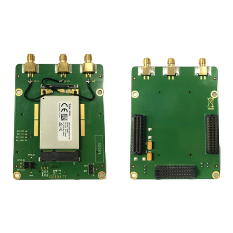
Figure 1: LGA DevKit SM package content
USB cable
LGA DevKit
Antenna
SMA cable
Jumpers
(SM or L)

Cinterion LGA DevKit User Guide
33
1VV123456 Rev. 0 Page 11 of 48 2023-9-22
Figure 2: LGA DevKit socket SML with LGA DevKit variants SM and L
Cinterion®LGA DevKit socket SML
(L30960-N0110-A100)
Cinterion®LGA DevKit L
(L30960-N0112-A100)
Cinterion®LGA DevKit SM
(L30960-N0111-A100)
LGA106
LGA114
LGA120 LGA156
SM L

1VV123456 Rev. 0 Page 12 of 48 2023-9-22
Cinterion LGA DevKit User Guide
33
2.9 Quickstart
Please complete the following steps to quickly get started with your LGA DevKit.
•Mount the LGA DevKit socket onto the LGA DevKit (for details see Section 2.10).
•Insert the fixing frame and then the module into the socket and close the retention
lid by pressing it down and turning it clockwise.
•Connect the provided antenna to the SMA connector named "MAIN".
•Check that the jumpers are set to their default delivery positions.
•Connect your host PC to either the USB or the USB VCP connector (depending on the
module). In case of USB VCP connections, install FT232R drivers.
•Set the switches PWR & ASC0 at the DevKit's lower right corner to "USB". Now, the
green "PWR" LED lights up.
•Shortly press the ON button to start the module. Now, the white "ON" LED lights up
The red "ERROR" LED may indicate issues that should be corrected. For details see Section
4.9.
Note: By scanning the QR code at the underside of the LGA DevKit you will also find further
information, videos and available drivers.

1VV123456 Rev. 0 Page 13 of 48 2023-9-22
Cinterion LGA DevKit User Guide
33
2.10 Mounting the LGA DevKit Socket
Before operating, the socket has to be mounted onto the LGA
DevKit with 4 screws. Scanning the QR code on the DevKit's under-
side and/or the quick start guide will lead you to the DevKit's web
home where you find a short introduction and video on how to do
this.
The white printing on the DevKit shows how the socket shall be ori-
entated and mounted. You can quickly adapt to different module footprints by using ded-
icated fixing frames. All contacts have low-resistivity needles.
Note: The module's thermal encapsulation inside the socket increases the thermal resis-
tance (Rth). Thus, you need to be aware that the board temperature may rise quite quickly
until automatic thermal shutdown takes effect, especially at higher environmental tem-
peratures or high radio output power.

1VV123456 Rev. 0 Page 14 of 48 2023-9-22
Cinterion LGA DevKit User Guide
33
3 LGA DeviKit Overview
3.1 Top and Underside View
Figure 3 and Figure 4 show the top and underside view of the of the LGA DevKit SM variant.
Please note that both SM and L variants of the LGA DevKit are identical - except or the MAIN
and DIV antenna connectors that are interchanged, and the footprint indicators showing
the different LGA module footprints.
Figure 3: LGA DevKit SM top view
Figure 4: LGA DevKit SM underside view
Error LED Configurable & interruptible signals
Adjustable
supply
Footprint indicator**
GPS
Activity LEDs
Channel select
Activity LED
USB VCP & PWR
Current test
USB & PWR
Supply mode
MAIN*
DIV*
* = MAIN and DIV antenna connectors are interchanged with the LGA DevKit Lvariant
** = Footprint indicator shows LGA156 footprint with the LGA DevKit Lvariant
DSB interface
PWR circuit
CTRL & Error det.
SIM Module footprint ex. GND Patch field
VCP FTDI
PWR buffer

1VV123456 Rev. 0 Page 15 of 48 2023-9-22
Cinterion LGA DevKit User Guide
33
3.2 Block Diagram
Figure 5: LGA DevKit block diagram
Jumper
PWR
Jumper
Jumper
Signal Jumpers
Jumper
Switch
ASC 0
Power Switch
FTDI
Serial – USB
Bridge
Auto Adjust
Levelshifter
Left side:
Modul e Pins
Right side:
Peripherals
Cinterion® Industrial Multifootprint
Power
80Pin
DSB75 / DSB
Mini
Connector
ASC 0 Micro
USB
Native Micro
USB
RF Main/ DRX
Antenna
Connector
On board
Sim
Connector
Combinded
Powering
MCU control unit
Error detection
LED
Footprint
detection
Button
ON
BTN
Button
RST
BTN
USB Data
Module Signals
Power
SIM
Antenna
ASC0 Signal
Module
Signals
Status LEDS
Power
User Interface/
Connectors Power BlockLogical Block Controlling
SIM2
ModuleSignaling
Start module
control Adjust BATT+
Capacitor Bank
LDO&
Protection
GPS
Connector
GPS
PWR
Module Signals
ASC0
Signal

1VV123456 Rev. 0 Page 16 of 48 2023-9-22
Cinterion LGA DevKit User Guide
33
4 LGA DevKit Interfaces
4.1 USB
The LGA DevKit comes with two USB interfaces supporting power supply and serial com-
munication. You may choose to setup communication via a module's USB port and/or a
module's UART (ASC0) port via FTDI232R VCP.
•Both USB ports can be used in parallel while power is sourced from both ports.
•The native USB power is isolated from the VCP USB power by a diode, meaning that
the VCP USB power does not feedback to the native USB power, but vice versa. This
should be taken into account when supplying the LGA DevKit from different USB
power sources, depending on the voltage levels there could be a power feedback
from native USB to VCP USB.
•In case of marginal USB power supply both USB ports should be used to improve
power capabilities.
Note: The modem's USB driver can be downloaded from the LGA DevKit's web page that
can be reached by scanning the QR code.
4.2 SIM
On the LGA DevKit's underside you find a SIM card holder that is connected to the module's
regular SIM interface lines, except for the CCIN line where the (default) jumper needs to be
set for CCIN at the CONTROL pin headers (see Section 4.3). However, some modules come
with an additional SIM interface. This can be accessed in conjunction with a DSB75/DSB-
Mini (as port extender) to support dual SIMs - with the DSB75/DSB-Mini serving as the sec-
ond SIM interface.
Some Cinterion®modules require additional components at the SIM interface, for instance
pull-up resistors managed by the DevKit's control logic. These can be overridden by setting
a switch on the DevKit's underside - see Figure 6. For modules requiring a CCIO pull up re-
sistor this switch should be set to "CCIO PULLUP" (see Section Section 7.3).
Figure 6: SIM settings

1VV123456 Rev. 0 Page 17 of 48 2023-9-22
Cinterion LGA DevKit User Guide
33
4.3 Pin Headers
The pin headers at the top side can be used to setup connections between modules and
possible on board peripherals. Thus, pin headers having signal names at their left side only,
namely the pin headers AUDIO, CONTROL, ASC0_A, ASC0_B, DAI, ASC1, GPIO, and PWR, can
be bridged by jumpers. All of these pin headers have the module's signal name on their left
side (marked yellow in Figure 7), whereas the right side corresponds to peripherals like level
shifters or the DSB connector (marked green in Figure 7).
•Placing a jumper connects a line through a level shifter to the associated pin at the
2x40 pin connector at the underside of the LGA DevKit (and thus to a connected
DSB75/DSB-Mini). See also Figure 5.
•Not placing a jumper leaves a module signal open.
External periphery can also be connected to all accessible module signals directly. When
connecting other external periphery to the pin headers pay attention not to violate the
maximum module ratings.
Figure 7: Pin headers

1VV123456 Rev. 0 Page 18 of 48 2023-9-22
Cinterion LGA DevKit User Guide
33
4.3.1 Default Configuration
Figure 8 shows the factory default jumper and switch positioning.
Figure 8: Default jumper and switch configuration
Please also verify that the SIM switch at the underside is set to default "CCIO Pullup dis-
abled".
4.4 ON Button: Module Start and Power Down
Pushing the ON button shortly (i.e., <0.5s), the LGA DevKit starts up and initially analyses
the mounted module orientation and type. In case both are recognized and correct, the
module is started using specific start pulses. The white LED indicates the module’s VEXT
state as high.
Also, it is possible to start up the module by toggling DTR on the DSB75/DSB-Mini RS232
connector.
Pushing the ON button for more than 2s shuts down the LGA DevKit's power supply, and
the module's power supply is interrupted regardless of its current state.
4.5 RST Button: Module Reset
Pushing the RST button pulls down a module's EMERG-RST/OFF signal, thus forcing it into
reset or off state. Please note that this functionality is only available if the (default) jumper
is set for EMERG_RST at the CONTROL pin block (see Section 4.3).
Control & ASC0
3x Jumper
USB USB

1VV123456 Rev. 0 Page 19 of 48 2023-9-22
Cinterion LGA DevKit User Guide
33
4.6 ASC0 Switch: Module UART Interface Selection
The "ASC0" switch selects the module's UART communication interface either via USB VCP
(FTDI232R) or via "RS232" D-Sub interface on the DSB75/DSB-Mini.
Changing this from "USB" to "RS232" during operation resets the FTDI VCP bridge in order
to release the signal lines, thus leading to a USB VCP disconnect on the host PC side.
4.7 PWR Switch: Power Source Selection
The "PWR" switch selects the preferred power source, both sources can be connected at
the same time, but do not supply the LGA DevKit in parallel.
When "USB" is set, both LGA DevKit USB ports will contribute to the overall power supply
with a connected DSB75/DSB-Mini having to be powered separately. Setting "EXT", the
power is supplied from the DSB75/DSB-Mini interface.
Please note that there is a dedicated power supply for the GPS antenna. To use this, the
two pins at the GPS_PWR field will have to be soldered and connected by jumper.
4.8 Free Level Shifters
The LGA DevKit provides 8 free level shifters, with 4 placed & connected at the patch field
on the underside, and 4 connected to the pin header "LEVELSHIFTER". The level shifters on
the pin header are referenced to the module's Vext, and Vref that by default corresponds
to 3V or to "REF IN" if connected (see Section 4.12.2).
These level shifters can be used to shift signals that are not available at the DSB connector.
4.9 LEDs
The LGA DevKit LEDs have the following meaning:
LED Meaning
RED Blinking continuously: Module is inserted wrongly oriented, not powered, turn by 180°
Blinking 2 times: No module inserted, not powered
Blinking 3 times: A module not supported by footprint is inserted, not powered, change
module
Lighting: Overcurrent detected in module power pass, change module, restart LGA
DevKit's power supply
GREEN Module TXD0 activity, low active
GREEN PWR Sufficient supply level, but not switched on
AMBER Module RXD0 activity, low active

1VV123456 Rev. 0 Page 20 of 48 2023-9-22
Cinterion LGA DevKit User Guide
33
4.10 Patch Field
A small patch field is available at the LGA DevKit's underside. If required, you can add simple
components (LED, Transistors etc.) here. All module signals, except USB and RF are acces-
sible at the underside by the labeled pads.
4 level shifters are accessible close to the patch field as well with the reference Vext and
Vref. The Vref related level shifter connections can also be accessed via four additional
pads at the left underside of the LGA DevKit where additional pins may be soldered.
Warning: The warranty may be lost if the patch field is soldered.
BLUE Module state GPIO5 / LED (if a jumper is set for GPIO5 at the GPIO pin headers)
WHITE ON Module started, V180/300 is at high level (if the (default) jumper is set for VEXT at the
CONTROL block)
WHITE USB TX/RX activity on USB VCP
LED Meaning
Table of contents
Other Telit Wireless Solutions Microcontroller manuals

Telit Wireless Solutions
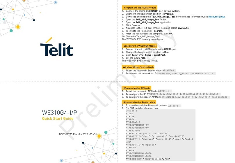
Telit Wireless Solutions WE310G4-I/P User manual

Telit Wireless Solutions
Telit Wireless Solutions LM940 1.0 Guide

Telit Wireless Solutions
Telit Wireless Solutions EVK Series User manual

Telit Wireless Solutions
Telit Wireless Solutions BlueDev+S42M User manual

Telit Wireless Solutions
Telit Wireless Solutions Cinterion LGA DevKit Things User manual

Telit Wireless Solutions
Telit Wireless Solutions SE873Q5 Specification sheet

Telit Wireless Solutions
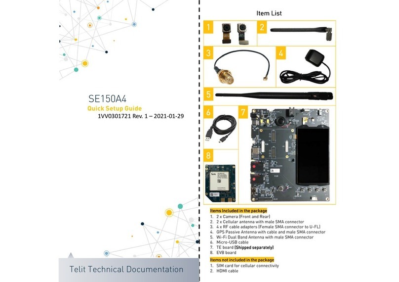
Telit Wireless Solutions SE150A4 User manual

Telit Wireless Solutions
Telit Wireless Solutions SE880 RDK User manual

Telit Wireless Solutions
Telit Wireless Solutions EVK4 User manual