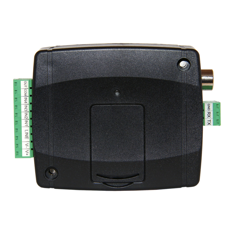
tell Adapter2 User manual

HU DE
EN
Adapter2
QUICK GUIDE FOR INSTALLERS
Dear customer,
Thank you for choosing our product. The full Installa-
tion and Application Manual is downloadable from the
manufacturer’s website:
https://tell.hu/en/products/gprs-communicators/
adapter2
PUTTING INTO OPERATION:
I. Choose the SIM card services according to the module functions you
would like to use (mobile internet, voice call, SMS service).
II. Remove the module’s plastic cover and insert the SIM card.
III. Check the installation environment for avoiding weak signal strength and
other problems (strong electromagnetic disturbances, high humidity).
IV. Connect the GSM antenna.
V. Make the correct wiring according to the module version.
VI. Connect the module to the power supply (12-24V DC, 500mA)!
SIM
1.
2.
3.
4.
SIM
5.
SIM

2
Attention! Do NOT connect the GSM antenna’s connector directly or
indirectly to the protective ground, because this may damage the
module!
Attention! Do NOT use the COM terminal for powering up the module, be-
cause this can lead to damaging the components!
-> Chapter 2 of the Installation and Application Manual
WIRING OF THE MODULE:
Module versions:
The Adapter2 can be mounted with European 2G, 3G, 4G or internation-
al 3GA and 4GA phones, can be equipped with PSTN as a backup, and
can be ordered in default and PRO version.
If you want to use the PSTN or line phone function, you need to get the
PSTN version of the Adapter2!
Inputs:
The NO and NC contacts are dened between the COM terminal and
the given input, while with the PSTN version, the contact is dened
between the negative V- terminal of the supply voltage and the se-
lected input.
The default Adapter2 has one input, the PSTN version has four.
The type of an input can be selected in the programming software.
Outputs:
The outputs can provide NO relay contacts, so the wiring should be
done accordingly. The module will switch the negative V- point of
the power supply to the output and can support a load of 1A.
The LINE is a simulated phone line output, which should be connected
to the RING-TIP input of an alarm system capable of phone line com-
munication.
The PSTN input is for connecting the phone line, while the PHONE out-
put is for connecting a landline telephone.

3
Adapter2 Quick Guide
Attention! Do NOT connect the module’s terminals directly or indi-
rectly to the protective ground because this may damage the module!
Transparent serial port:
The Adapter2 has a transparent serial port, which is suitable for bidirec-
tional transparent data transfer over the Internet. The wiring needed
for this function diers on a case to case basis, and is highly dependant
on the connected device and the need for a logic level converter. For
more information on this process, see the Installation and Application
Manual of Adapter2.
Adapter2 – Alarm system wiring with GSM backup:
V+ V- LINE IN2IN1 IN3 IN4 COM OUT
NO
Control
NC
NO
NO
12-24 VDC
RING TIP
Alarm System
NC
+
-

4
Adapter2 PSTN – Alarm system wiring with PSTN backup:
-> Chapter 2 of the Installation and Application Manual
PROGRAMMING SOFTWARE:
The latest version of the programming software is available on the manu-
facturer’s website.
Permission levels:
The Adapter2 uses dierent user levels. The superadmin authorization
level used during the installation has full access to all settings of the
module.
Default superadmin password: 1234
For more information on the permission levels, see the Installation and
Application Manual of Adapter2.
Attention! It is highly recommended that you modify the default
passwords after the rst login. This can be done with the password
icons in the Connection type submenu of Connection menu.
V+ V- LINE IN1PSTN PHONEOUT
Control
Landline
input
12-24 VDC
RING TIP
Alarm System
+
-
Telephone

5
Adapter2 Quick Guide
USB connection :
▪Launch the Adapter2 programming software!
▪Connect the module via USB A-B cable to the computer!
▪Select the USB option in the Connection type submenu!
▪Enter the Connection password then push the button!
PIN-code, APN and Cloud:
After a successful USB connection, select the General submenu of the
Device Settings menu. Here, in the SIM section, you can set the SIM
card’s PIN code and the APN specied by your provider.
In the Cloud server section enter the server details and set the Cloud
usage.
Default server url: 54.75.242.103
Default server port: 2020
If the Cloud usage option is enabled, the device can be accessed at any
time via the cloud server. Otherwise it will only connect upon request
sent by SMS to the phone number of the SIM card:
*CONNECT,PWD=device password#
(e.g. *CONNECT,PWD=1234#)
After a successful connection is established, the device sends a re-
sponse SMS, which contains the server data and the Device ID.
Device ID:
The Device ID, which is necessary for remote connection can be located
in the Status monitoring submenu of the Device status menu.
Cloud connection :
▪Launch the Adapter2 programming software!
▪Select the Cloud option in the Connection type submenu!
▪Enter the server details and the Device ID!
▪Enter the Connection password then push the button.
For further connection options, see the Installation and Application
Manual of Adapter2.
-> Chapter 3 of the Installation and Application Manual

6
LED SIGNALS:
Slowly ashing green: Connected to GSM network, normal operation
Flashing green and red: Event reporting in progress
Flashing red: GSM service unavailable or system restart in progress
Permanent red: SIM card error
PROGRAMMING THE MODULE:
Built-in help:
Detailed help is available for each menu of the programming software
by clicking the Help button at the top right corner.
Congure notications and remote monitoring:
The data of CMS (Central monitoring station) servers can be added
at the top of the Reporting channels menu. In addition to typing the
name, you also need to set the receiver’s IP address/domain and port,
the protocols you want to use, and the supervision settings.
The device can also send notication by voice call or SMS, and in case
of a PRO device, the email and Push notications are also available.
Also the necessary phone numbers and e-mail addresses can be added
in the Reporting channels menu.
In order to signal a CID code to a CMS, rst you need to create a noti-
cation template from the previously added servers in the Notication
template menu. You can create a notication template by clicking on
New button, then you need to select the servers you want to use and
set their priority.
IP cameras:
The Adapter2 PRO versions can handle up to 4 IP camera images at
once. A new camera can be added in IP cameras menu by entering
a name and the camera URL. The camera type can be Stream or Picture
depending on the URL.
For obtaining the URL of your IP camera we recommend our IP Camera
detector software that is made with this purpose in mind. It is available
on tell.hu.

7
Adapter2 Quick Guide
Event settings:
The events of Adapter2 can be divided into three groups that can be
set dierently.
Inputs and Input events:
The type and sensitivity of the inputs can be set in the Inputs menu. In
order for a contact input to generate an event, you need to add a New
input event in the Input events menu.
New input events:
▪Enter the Name and Type of the event!
▪Select the Input!
▪Add the Event Code, Partition and Zone!
▪Select the Notication template!
Service events:
The Adapter2 can perform various actions as a result of service events.
To do this, you need to add a new service event in the Service events
menu by clicking the New button.
After adding a new service event:
▪Enter the Name and Type of the event!
▪Select the Event from the list!
▪Add the Event Code, Partition and Zone!
▪Select the Notication template!
Alarm system events:
The device is capable of performing actions as a result of an event
coming from an alarm system. To do this, you need to add a new event
in the Service events menu by clicking the New button.
After adding a new alarm system event:
▪Enter the Name and Type of the event!
▪Add the Event Code, Partition and Zone!
▪Select the Notication template!
Assigning notications and controls to events:
When adding an event, you can assign multiple notication and output
control actions to it.
Available actions:
▪Output control in monostable, bistable or pulse series mode.
▪Voice call notication with customizable Voice messages.

8
▪IP-based reporting to CMS.
▪Text-based notications via SMS or e-mail (e-mail for PRO version only).
▪Push notication sending with camera image (PRO version only).
Attention! To send Push messages, you must assign at least one
mobile app to the device!
-> Chapter 4 and 5 of the Installation and Application Manual
ASSIGNING MOBILE APP:
You can assign 4 mobile apps to an Adapter2 Pro. The application used
is called TELL Control Center and is available on both Android and iOS
platforms.
System requirements:
▪Minimum Android version: 4.2
▪Minimum iOS version: 8
Before adding:
▪Set up a Registration password in the programming software’s Mobile
devices submenu!
▪Generate QR-code by clicking the QR-code button.
Adding a device:
▪After starting the app scan the generated QR-code!
▪Enter a chosen Username (this identies the app in the module)!
▪Enter the Registration password!
▪Enter a chosen Device name (this identies the module in the app)!

9
Adapter2 Quick Guide
Main functions of TELL Control Center:
▪Display Online/Oine status.
▪Display GSM signal strength and power supply.
▪Display rmware version.
▪Display status of inputs and outputs.
▪Remote output control.
For more information about TELL Control Center features, see the TELL
Control Center User Guide, which can be found on tell.hu.
-> TELL Control Center User Guide
SAFETY INSTRUCTIONS
For your safety, please read carefully and follow the instructions below!
Failure to observe safety instructions may be a threat to you and
your environment!
TELL’s product (hereinafter referred to as „device”) has a built-in
mobile communication modem. Depending on the product version,
the built-in modem is capable of 2G, 3G or 4G mobile communication.
The 2G modem can use the following frequency bands:
850/900/1800/1900 MHz @GSM/GPRS
The 3G modem can use the following frequency bands: 900/2100 MHz
@UMTS, 900/1800 @GSM/GPRS
The 3GA modem can use the following frequency bands:
800/850/900/1900/2100 MHz @UMTS, 850/900/1800/1900 MHz @GSM
The 4G modem can use the following frequency bands: 900/1800
MHz@GSM/EDGE, B1/B8@WCDMA, B1/B3/B7/B8/B20/B28A@LTE

10
The 4GA modem can use the following frequency bands: B2/B4/B5@
WCDMA, B2/B4/B5/B12/B13@LTE
• DO NOT USE the device in an environment where radiofrequency
radiation can cause a risk and may interfere with other devices,
that may cause undesired operation - such as medical devices!
• DO NOT USE the device if there’s a risk of high humidity, hazardous
chemicals or other physical impact!
• DO NOT USE the device beyond the specied operating temperature
range!
• DO NOT MOUNT the device in hazardous environment!
• DO NOT INSTALL/WIRE the device under voltage. For easy discon-
nection, the device’s adapter or power supply should be easily
accessible!
• ALWAYS DISCONNECT the power supply before starting to mount
the device!
• ALWAYS DISCONNECT the device’s power supply before inserting,
removing or replacing the SIM card!
• TO SWITCH OFF the device disconnect all power sources, including
power supply and USB.
• The computer connected to the device must always be connected
to the protective ground!
• DO NOT USE a computer to program the device that is not connected
to the protective ground. To avoid ground looping, the power supply
of the computer and the device must use the same grounding!

11Adapter2 Gyorstelepítési Útmutató
Adapter2
GYORSTELEPÍTÉSI ÚTMUTATÓ TELEPÍTŐKNEK
Tisztelt Vásárlónk!
Köszönjük, hogy megvásárolta termékünket! A teljes
Telepítési és Alkalmazási Útmutató letöthető a gyártó
weboldaláról:
https://tell.hu/hu/termekek/gprs-kommunikatorok/
adapter2
ÜZEMBE HELYEZÉS:
I. A használni kívánt funkciók alapján válasszunk szolgáltatásokat a SIM
kártya szolgáltatónál (mobilinternet, hívásszolgáltatás, SMS szolgáltatás)!
II. Távolítsuk el a modul műanyag fedelét majd helyezzük be a SIM
kártyát!
III. Ellenőrizzük a telepítési környezetet gyenge térerő és egyéb prob-
lémák elkerülése érdekében (erős elektromágneses zavarok, magas
páratartalom)!
IV. Csatlakoztassuk a GSM antennát!
V. Végezzük el a modul bekötését a modul verziónak megfelelően!
VI. Csatlakoztassuk a modult tápfeszültséghez (12-24V DC, 500mA)!
SIM
1.
2.
3.
4.
SIM
5.
SIM

12
Figyelem! A GSM antenna csatlakozóját se közvetlenül, se közvetve NE
csatlakoztassa védőföldhöz, mert ez a modul meghibásodását okoz-
hatja!
Figyelem! A COM terminált NE használja a modul megtáplálására, mert
ez a modul meghibásodását okozhatja!
-> Telepítési és Alkalmazási Útmutató 2. fejezet
MODUL BEKÖTÉSE:
Modul verziók:
Az Adapter2 kommunikáció tekintetében 2G, 3G, 4G és nemzetközi 3GA
valamint 4GA telefonnal szerelve, funkciók terén PSTN tartalékkal vagy
a nélkül, sima és PRO verzióban rendelhető.
APSTN és a vezetékes telefon funkció használatához Adapter2 PSTN ver-
ziója szükséges!
Bemenetek:
Az NO vagy NC kontaktust az alap modul esetén a kiválasztott beme-
net és a COM terminál között, a PSTN verziónál a kiválasztott bemenet
és a tápfeszültség negatív V- pontja között értelmezzük.
Alap modul négy bemenettel, a PSTN verzió egy bemenettel rendelkezik.
A bemenetek típusát a programozó szoftverben választhatjuk ki.
Kimenet:
A kimenet NO állapotú relékontaktust szolgáltat, ennek megfelelő bekö-
tés szükséges az adott munkafolyamat elvégzéséhez. Az eszköz a táp-
feszültség negatív V- pontját kapcsolja a kimenetre és maximum 1A-rel
terhelhető.
A LINE egy szimulált telefonvonal-kimenet, amit vezetékes telefon-
kommunikátorral rendelkező riasztók RING-TIP bemenetére lehet kötni.
A PSTN bemenet a vezetékes telefonvonal bekötésére szolgál, a PHONE
kimenetre pedig egy vezetékes telefonkészüléket lehet csatlakoztatni.

13Adapter2 Gyorstelepítési Útmutató
Figyelem! Ne csatlakoztassa a modul termináljait se közvetlenül, se
közvetve védőföldhöz, mert ez a modul meghibásodását okozhatja!
Transzparens soros port:
Az Adapter2 rendelkezik egy transzparens soros porttal is, mely inter-
neten keresztüli kétirányú transzparens adatátvitelre alkalmas. Ennek
a bekötése nagyban függ csatlakoztatott berendezéstől, és a szintil-
lesztés szükségességétől. Részletesebb információt erről a folyamatról
az Adapter2 Telepítési és Alkalmazási Útmutatójában talál.
Adapter2 – Riasztó példa bekötés GSM tartalékkal:
V+ V- LINE IN2IN1 IN3 IN4 COM OUT
NO
Vezérlés
NC
NO
NO
12-24 VDC
RING TIP
Riasztóközpont
NC
+
-

14
Adapter2 PSTN – Riasztó példa bekötés PSTN tartalékkal:
-> Telepítési és Alkalmazási Útmutató 2. fejezet
PROGRAMOZÓ SZOFTVER:
A programozó szoftver legfrissebb változata elérhető a gyártó web-
oldaláról.
Jogosultsági szintek:
Az Adapter2 többféle jogosultságszinttel dolgozik. A telepítés során
használt szuperadmin jogosultsági szint teljes hozzáféréssel rendelkezik
a modul minden beállításához.
Gyári szuperadmin jelszó: 1234
További információt a felhasználói szintek működéséről a Telepítési és
Alkalmazási Útmutatóban talál.
Figyelem! Az első belépéskor erősen ajánlott módosítani a modul
gyári jelszavait a programozó szoftver Kapcsolat menü Kapcsolódási
mód almenüjében található a jelszó ikonok segítségével!
V+ V- LINE IN1PSTN PHONEOUT
Vezérlés
Vezetékes
telefonvonal
12-24 VDC
RING TIP
Riasztóközpont
+
-
Telefonkészülék

15Adapter2 Gyorstelepítési Útmutató
USB elérés :
- Indítsa el az Adapter2 programozó szoftvert!
- Csatlakoztassa a modult USB A-B kábelenkeresztül a számítógéphez!
- A Kapcsolódási mód almenüben válassza az USB opciót!
- Adja meg a Csatlakozási jelszót, majd nyomjon a gombra!
PIN-kód, APN és Felhő:
Sikeres USB kapcsolat után válasszuk a Modulbeállítások menü Általá-
nos beállítások almenüjét. Itt a SIM mezőben beállíthatjuk a SIM kártya
PIN-kódját és a szolgáltatója által megadott APN-t.
A Felhő mezőben állítsuk be a szerver adatokat és a Felhőhasználatot.
Gyári szerver url: 54.75.242.103
Gyári szerver port: 2020
A Felhőhasználat engedélyezésével az eszköz távolról mindig elérhető
lesz, amennyiben viszont tiltjuk, az eszköz távoli eléréséhez egy SMS
parancsot kell küldenünk a SIM kártyához tartozó telefonszámra:
*CONNECT,PWD=moduljelszó#
(pl. *CONNECT,PWD=1234#)
Az eszköz sikeres csatlakozás után válasz SMS-t küld amely a szerver
adatokat és az Eszközazonosítót tartalmazza.
Eszköz azonosító:
A távoli eléréshez elengedhetetlen Eszközazonosítót a Modulállapot
menü Állapotgyelés almenüjében találja.
Távoli elérés :
▪Indítsa el az Adapter2 programozó szoftvert!
▪A Kapcsolódási mód almenüben válassza a Felhő opciót!
▪Adja meg a szerver adatokat és a modul Eszköz azonosítóját!
▪Adja meg a Csatlakozási jelszót, majd nyomjon a gombra.
Egyéb távoli kapcsolódási lehetőségeket találhat a Telepítési és Alkal-
mazási Útmutatónkban.
-> Felhasználói Útmutató 3. fejezet

16
LED JELZÉSEK:
Lassú zöld villogás: GSM kapcsolat, üzemszerű működés
Zöld és piros villogás: Esemény bejelzése folyamatban
Pirosan villog: GSM hálózat nem elérhető, vagy újraindítás folyamatban
Folyamatos piros: SIM-kártya hiba
MODUL PROGRAMOZÁSA:
Beépített súgó:
A programozó szoftver helyérzékeny súgója minden menüből elérhető
a jobb felső sarokban található Segítség gombra kattintva.
Értesítések és távfelügyelet kongurálása:
Az Értesítési csatornák menü tetején tudjuk felvenni az egyes távfel-
ügyeleti vevőegységek adatait. A név begépelése mellett szükség van
még a vevő IP címére és portjára, a használni kívánt protokollokra és
életjel beállítására.
Az eszköz e mellett képes még SMS és hívás útján kiértesíteni, PRO
eszköz esetén pedig az e-mail és Push értesítés is elérhető. Az ehhez
szükséges telefonszámok és e-mail címek is az Értesítési csatornák
menüben adhatók meg.
Ahhoz, hogy egy CID kódot egy távfelügyelet felé be tudjunk jelezni,
először létre kell hozni egy értesítési sablont a felvett vevőegységekből
az Értesítési sablonok menüpontban. Értesítési sablont az Új gombra
nyomva tudunk létrehozni, ehhez pedig ki kell választanunk a használni
kívánt vevőegységeket és be kell állítanunk a prioritásukat.
IP kamerák:
Az Adapter2 PRO verziók egyszerre 4 db IP kamerakép kezelésére képe-
sek. Új kamerát felvenni az IP kamerák menüben a kameranév és egy
URL megadásával tudunk. A kamera típusát az URL-től függően kell
beállítani Élőképnek vagy Pillanatképnek.
Az IP kamerája linkjének kinyeréséhez ajánlani tudjuk a külön erre a cél-
ra készített IP Kamera kereső szoftverünket, melyet a tell.hu oldalon
találhat meg.

17Adapter2 Gyorstelepítési Útmutató
Események programozása:
Az Adapter2 eseményeit három csoportba soroljuk, ezeket külön-külön
kell beállítani.
Bemenetek és Bemeneti események:
A használt bemenetek típusát és érzékenységét a Bemenetek menüben
állíthatjuk be. Ahhoz, hogy egy bemenetre érkező kontaktus eseményt
hozzon létre, a Bemeneti események menüben hozzá kell adnunk egy
Új bemeneti eseményt.
Új bemeneti eseménynél:
▪Adjuk meg az esemény Nevét és Típusát!
▪Válasszuk ki a Bemenetet!
▪Határozzuk meg az Eseménykódot, a Partíciót és a Zónát!
▪Válasszuk ki a távfelügyeleti Értesítési sablont!
Szervizesemények:
Az Adapter2 rendelkezik egy szervizesemény készlettel, és ezek ha-
tására az eszköz különböző műveleteket képes végrehajtani. Ehhez
a Szervizesemények menüben hozzá kell adnunk egy szervizese-
ményt az gombra kattintva.
Új szervízesemény felvétele után:
▪Adjuk meg az esemény Nevét és Típusát!
▪Válasszuk ki a kívánt Eseményt a szervízesemény készletből!
▪Határozzuk meg az Eseménykódot, a Partíciót és a Zónát!
▪Válasszuk ki a távfelügyeleti Értesítési sablont!
Riasztóközpont-események:
Az eszköz egy riasztóközponttól érkező események hatására is képes
műveletek végrehajtására. Ehhez a Riasztóközpont-események menü-
ben hozzá kell adnunk egy új eseményt az Új gombra kattintva.
Új riasztóközpont-esemény felvétele után:
▪Adjuk meg az esemény Nevét és Típusát!
▪Határozzuk meg az Eseménykódot, a Partíciót és a Zónát!
▪Válasszuk ki a távfelügyeleti Értesítési sablont!
Értesítések és vezérlések eseményekhez rendelése:
Minden eseményhez rendelhetünk értesítéseket és kimenetvezérlést
az esemény felvételekor.

18
Beállítható műveletek:
▪Kimenetvezérlés monostabil, bistabil vagy impulzussorozat formában.
▪Hanghívásos értesítés a személyre szabható Hangüzenetek használatával.
▪Távfelügyelet értesítése IP alapon.
▪Szöveg alapú SMS és e-mail értesítés (e-mail csak PRO verziónál).
▪Push értesítés kamerakép küldéssel (csak PRO verzió).
Figyelem! A Push üzenetek kiküldésének feltétele legalább egy mobi-
lalkalmazás hozzárendelése a modulhoz!
-> Felhasználói Útmutató 4. és 5. fejezet
MOBILALKALMAZÁS HOZZÁRENDELÉSE:
Az Adapter2 PRO változataihoz lehetőségünk van mobilalkalmazást
rendelni. Ez az alkalmazás a TELL Control Center, elérhető Android és
iOS platformon egyaránt.
Rendszerkövetelmények:
▪Minimális Android verzió: 4.2
▪Minimális iOS verzió: 8
Hozzárendelés előtti lépések:
▪Regisztrációs jelszó beállítása programozó szoftver Mobileszközök
almenüjében.
▪QR-kód generálása ugyanitt a QR-kód<QR-kód ikon> gombra kattintva.
Eszköz hozzárendelése:
▪Az alkalmazás elindítása után olvassuk be a generált QR-kódot!
▪Adjunk meg egy tetszőleges Felhasználónevet (ez az alkalmazás
azonosítására szolgál a modulban)!

19Adapter2 Gyorstelepítési Útmutató
▪Adjuk meg a Regisztrációs jelszót!
▪Adjunk meg egy tetszőleges Eszköznevet (ez a modul azonosítására
szolgál az alkalmazásban)!
A TELL Control Center főbb funkciói:
▪Online/Oine állapot kijelzése.
▪GSM térerő és tápfeszültség kijelzése.
▪Firmware verzió kijelzése.
▪Bemenet és kimenet állapotok kijelzése.
▪Kimenetek távoli vezérlése.
A TELL Control Center további funkcióiról a TELL Control Center Hasz-
nálati Útmutatóban olvashat, melyet a tell.hu oldalon találhat meg.
-> TELL Control Center Használati Útmutató
BIZTONSÁGI UTASÍTÁSOK
Biztonsága érdekében kérjük gyelmesen olvassa végig és kövesse az
alábbi utasításokat! A biztonsági utasítások esetleges be nem tartá-
sa veszélyt jelenthet Önre és a környezetére is!
A TELL terméke (továbbiakban „eszköz”) beépített mobilkommuniká-
ciós modemmel rendelkezik. Termékváltozattól függően, a beépített
modem 2G, 3G vagy 4G mobilkommunikációra képes.

20
A 2G modem az alábbi frekvenciasávokat használhatja:
850/900/1800/1900 MHz @GSM/GPRS
A 3G modem az alábbi frekvenciasávokat használhatja: 900/2100 MHz
@UMTS, 900/1800 @GSM/GPRS
A 3GA modem az alábbi frekvenciasávokat használhatja:
800/850/900/1900/2100 MHz @UMTS, 850/900/1800/1900 MHz @GSM
A 4G modem az alábbi frekvenciasávokat használhatja: 900/1800
MHz@GSM/EDGE, B1/B8@WCDMA, B1/B3/B7/B8/B20/B28A@LTE
A 4GA modem az alábbi frekvenciasávokat használhatja: B2/B4/B5@
WCDMA, B2/B4/B5/B12/B13@LTE
• NE HASZNÁLJA az eszközt olyan környezetben, ahol a rádiófrek-
venciás sugárzás veszélyt okozhat és egyéb eszközökkel interfe-
rencia alakulhat ki, amely megzavarhatja azok működését - például
egészségügyi eszközök!
• NE HASZNÁLJA az eszközt magas páratartalom vagy veszélyes
kemikáliák, vagy egyéb zikai behatások fennállása esetén!
• NE HASZNÁLJA az eszközt a megadott működési hőmérséklettarto-
mányon kívül!
• NE TELEPÍTSE az eszközt veszélyes környezetben!
• TILOS az eszközt feszültség alatt felszerelni / bekötni. A könnyű
áramtalaníthatóság érdekében az eszköz hálózati adaptere, vagy
tápegysége legyen könnyen elérhető helyen!
• MINDIG VÁLASSZA LE az eszközt a tápfeszültségről a felszerelés
megkezdése előtt!
• MINDIG VÁLASSZA LE az eszközt a tápfeszültségről a SIM kártya
behelyezése, eltávolítása vagy cseréje előtt!
• AZ ESZKÖZ KIKAPCSOLÁSÁHOZ válassza le az eszközről az összes
áramforrást, beleértve a tápfeszültséget és az USB csatlakozást is!
Other manuals for Adapter2
3
Table of contents
Languages:
Other tell Adapter manuals
Popular Adapter manuals by other brands

golden interstar
golden interstar Xpeed LAN 500 user manual

Ideal Life
Ideal Life ICE0001 instruction manual

TRENDnet
TRENDnet TU-PS2 Quick installation guide

D-Link
D-Link DWL-122 Quick installation guide

Buffalo
Buffalo AirStation G54 Quick setup guide

Quatech
Quatech Asynchronous Communications Adapter for PCI bus... user manual

LevelOne
LevelOne WUA-0614 Quick installation guide

SysKonnect
SysKonnect SK-98xx V2.0 user manual

Newer Technology
Newer Technology MAXPower802.11n user manual

Logik
Logik LNP90W17 instruction manual

Sony
Sony AC-E45A - Worldwide AC Power Adaptor operating instructions

Mitsubishi Electric
Mitsubishi Electric PAC-SA89TA-E instruction manual