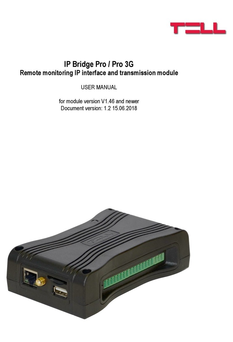
tell IP Bridge Pro User manual

HU DE
EN
IP Bridge PRO
QUICK GUIDE
Dear customer,
Thank you for choosing our product. The full User manual
is downloadable from the manufacturer’s website:
https://tell.hu/en/products/gprs-communicators/
ip-bridge-pro
WIRING OF THE MODULE
Connectors from left to right:
LINE: Simulated telephone line for connecting alarm panel
Z1: 1. contact input (considered between Z1 and COM)
COM: Common terminal between Z1 and Z2 contact inputs
Z2: 2. contact input (considered between Z2 and COM)
Z3: 3. contact input (considered between Z3 and COM)
COM: Common terminal between Z3 and Z4 contact inputs
Z4: 4. contact input (considered between Z4 and COM)
Z5: 5. contact input (considered between Z5 and COM)

2
COM: Common terminal between Z5 and Z6 contact inputs
Z6: 6. contactus input (considered between Z6 and COM)
TX: RS232 serial port TX
RX: RS232 serial port RX
GND: RS232 serial port GND
V+: Supply voltage 12-24V DC
V-: Supply voltage negative polarity (GND)
Connect the inputs accordingly to the congured control mode, nor-
mally open (N.O.) or normally closed (N.C.).
The device has 6 potential free, normally open (N.O.) relay contacts
(OUT1..OUT6 from left to right).
Attention! The maximum loads supported by the outputs is 1A @ 12V DC.
In case of higher load or higher voltage please use an external relay!
If the module has a 3G modem, use the 3G antenna connector to wire
the antenna.
Insert the SIM card into the socket until it clicks. To remove, press the
card again.
The module’s network is congurable through the USB host.
Connect the local internet network cable (LAN) coming from the router
to the Ethernet connector of the IP Bridge.
-> Chapter 3 of the User manual

3
IP Bridge PRO Quick Guide
PUTTING INTO OPERATION
After mounting and connecting the local Internet network, the device
can be powered up. Setting up the module can be done from any com-
puter that is connected to the same local network as the device is.
By default the device is delivered with DHCP setting. To detect the IP
address assigned by the local router, use the IP Bridge Virtual Client
program, which is downloadable from the product page if necessary. If
UDP Broadcast service is not allowed on the router, the program is not
able to locate the device. In this case you can check the IP address in
the router’s DHCP list.
If you’d also like to use the device’s web interface through the inter-
net, set up on your router the port forwarding of port no. 80 and port
no. 443 at the module’s IP address.
A text le copied to a USB ash drive can be used to modify the mod-
ule’s network conguration. For details on how to proceed and for the
format of the text le see chapter 5.3 of the User Guide.
-> Chapter 5 of User manual
WEB INTERFACE
Enter the module’s IP address into your browser to open the web in-
terface (e.g: 192.168.1.198) and enter the username and password for
login.
In default there are an admin and an additional user in the system. The
default login credentials are:
Username / Password: admin / admin
Username / Password: user / user
Attention! Make sure to change default passwords at your rst login.
You can do so on the General settings page.

4
MODULE STATUS
The module displays the module status page after login. In the header
you can nd the language selector , the view mode selector and
the logout button. In the view mode selector window you can make a
backup of your settings or you can also upload a previously saved one.
Attention! The saved conguration le contains sensitive data.
Please store it accordingly.
In the header the basic status information is displayed: the module’s
date/time, current LAN IP address, supply voltage, the module’s re-
mote monitoring group ID and device ID and the simulated phone line
status. In addition, if the IP Bridge has an extension panel, the mobile
internet’s IP address, the signal strength in percentage, the IMEI num-
ber and the SIM ID are also here.
The input section indicates the current status of the inputs. It is fol-
lowed by the output section, where the status of the outputs are indi-
cated and the outputs can be also controlled from here. The next sec-
tion shows the status of connections to the remote monitoring servers.
The Event Log section lists the last 10 events, which may be events
received from the alarm control panel or the internal events of the
device. The full event list (maximum 500 events) is available with the
More events button.
The Event Log shows the date and time of the event, CID code, the sta-
tus of reporting to a monitoring station ( ), the status of VOIP
notications ( ), the status of SMS notications ( ),
the status of saving camera images ( ), the status of email sending
(), the status of uploading camera images to FTP ( ), the status
of displaying event in TMS ( ), the status of relay control ( ) and
the status of push notication sending ( ). You can also check
the camera images recorded in association with the event and the
details of Settings changed events .
-> Chapter 6.1 User manual

5
IP Bridge PRO Quick Guide
GENERAL SETTINGS
On the General tab of Settings menu, you can change the settings of
communication and operation.
Some of the most important features are:
Users: You can change the username and password of both user levels
here. And also the RADIUS server needed to add and manage additional
users can be added here.
Account ID and TEX ID: The identier for reporting to remote monitor-
ing stations can be added here.
Ping servers: To monitor the internal and external network, you can
congure 2-2 ping servers. If the module has an extension panel, you
can add 2 additional servers to monitor the mobile internet.
Battery: If the supply voltage falls below the alarm threshold for at
least 30 seconds, Battery fault internal event is generated. If the sup-
ply voltage returns above the restore threshold for at least 30 seconds
Battery restore internal event is generated.
FTP/SFTP: The device can upload the camera images captured at the
time of the alarm to the server provided here. To do this, enter the
server’s IP address. If needed, add the port number separated by a co-
lon (e.g. 192.168.1.1:8181). If necessary, specify the path of the image
folder, as well as the username and password.
TMS server: In addition to contact ID messages, the device can also
forward the captured camera images and live URLs to the TMS server
set up here.
Update server:If the Firmware update server is not set, in default the
module downloads the rmware update from the server provided by
the manufacturer, but you can add a dierent server as well.
Firmware update: Notication about the new rmware update will be
sent to the email addresses set here. You can set when to check if
there is a new update and you can choose how to download and install
the update manually or automatically.
Default settings: The device settings will reset to the factory settings,
but the current rmware version won’t change.
For further details on the settings described above and other options
see chapter 6.2 of the User manual.

6
SERVERS
To report events to a monitoring station you need to create server
groups. These server groups can be assigned to events you want to
report. To do so, rst add up to 6 monitoring servers, then create up to
6 groups from the servers.
To add a Server enter a name, the IP address or domain name of the
server, the port number, select the network and the receiver’s type
and set the testing details. If the module doesn’t have an extension
panel the only option is LAN and the network selector is not displayed.
In case of a SIA IP receiver the AES key can be set.
To add a server group, give it a name, then create a group from the pre-
viously added servers and mark the primary ones. The device attempts
to report the events to each primary server at least once. If the event
is not reported to at least one primary server within 10 minutes, the
device attempts to report it to the backup servers. If reporting to one
of the backup servers succeeded, the device won’t report the event to
the others.
-> Chapter 6.3. of User manual
CAMERAS
By clicking the Cameras menu, IP Bridge automatically nds and lists
IP cameras that support the ONVIF recommendation and are connected
to the same network.
If the password-free connection to the IP camera is enabled, the device
lists the proles that are set in the camera, which can be checked by
clicking the Prole dependent parameters. Otherwise you can add the
username and password for login, and also the ONVIF port on which the
IP Bridge can communicate with the camera.
The proles can be added to the camera list with the Add to list button,
but you can also add camera manually by entering its URL. To do this,
press the View/edit button in the Added cameras section. A camera
with external address can cause high data trac.
Attention! Depending on the camera resolution, the SD card may be full
after 5-10 thousand events for which camera recording is required. In this
case, the device can not store additional camera images until the previ-
ously recorded images are deleted. You can do this in the Cameras menu.
-> Chapter 6.4. User manual

7
IP Bridge PRO Quick Guide
MOBILE APPLICATION
The IP Bridge is able to send Push message due to an event, and the
status of the inputs can be checked and also controlled through the
mobile application. The TELL Control Center is available in the App Store
and in the Play Store.
First enable this service on the Mobile application tab, then set the IP
address and port of the server used for Push sending and then select
the network type and backup network type. In default the server set-
ting elds are lled with the data of manufacturer’s server reserved
for this purpose, and the network is the Default network set on the
General tab.
Server IP: 54.75.242.103
Port: 2020
4 mobile devices can be registered for the module. Each slot has a uniqe
identier that can be displayed by clicking the QR code button at the end
of the line. In the mobile application you can register a device into the
module by scanning the QR code of the given slot. After the registration
the mobile application’s ID and the mobile device’s name are listed here.
-> Chapter 6.6 of the User manual
EVENT SETTINGS
Internal and external events of the module can be congured on the
Events tab of Settings menu item. You can add unique names to the
events, that appear in the event log and reports. The names of the
inputs are also displayed in the status menu.

8
External events: Up to 20 external events can be set in the module,
which are Contact ID events received on the simulated phone line. This
can be done with the Add more button at the bottom of the Events page.
The event settings are divided into 8 groups, and you can switch be-
tween them by the arrows in the header of the table.
Input properties
Input type: according to the wiring NO (normally open) or NC (normally
closed)
EOL: This option enables tamper protection on the given input.
Sensitivity (ms): The status change of the given zone input is ignored
if it is shorter than the value set here.
Bypass: Bypassed events are not generated.
Notify next: By selecting this checkbox the next event will be generat-
ed even if the CID code corresponds to this event.
Event codes
Each internal event can be associated with a Contact ID code, but the
CID code, partition and zone can also be modied.
Monitoring station settings
To report an event to a remote monitoring station, you need to En-
able reporting, and select the Server group that you want to report
the events Contact ID code to. Reporting to TMS should be enabled
separately.
E-mail settings
You can set up email notication about the events here. The recipient
list, subject and email body are editable by clicking the icon. To add
multiple addresses separate them by comma.
Camera settings
The cameras already added to the module can be assigned with the
events here. If an event occurs, the last 5 images recorded by the cam-
era which is assigned to the given event are sent via e-mail, or upload-
ed to FTP/SFTP server or forwarded to TMS.
VOIP (SIP) settings
V1-V4 columns indicate the phone numbers specied in the Voice call
section of VOIP menu. You can choose which of these you want to be
notied when the event occurs. In the Acknowledgement column you
can select the acknowledgement type (no ack/ with * button/ ack.
upon call reject). In each case, the reporting to other phone numbers

9
IP Bridge PRO Quick Guide
can be stopped by pressing the # button. In case of Ack. upon call
reject option accepting the call also conrms the event automatically
and reporting to the further phone numbers can be stopped by press-
ing the # key on the phone. You can also select the audio le you want
to be played during the voice call.
SMS settings
The phone numbers indicated by SMS1-SMS4 columns can be set in the
SMS section of VOIP menu. The SMS text can be edited by pressing the
icon.
Mobile settings
The MOBIL1-MOBIL4 columns mean the mobile devices listed in the Mo-
bile application menu. The message set in the Push notication text
column will be sent to the selected devices.
With this icon you can copy all the settings from the rst row to
all other rows.
For details on events and their settings see chapter 6.7 of the User manual.
REMOTE MODULES
You can add remote IP Bridge modules to your device and use them for
transparent serial data transfer or for controlling the remote devices’
output. You can add up to 6 remote IP Bridge modules to your device
by adding the following data:
Address: The IP address of the device. If the remote module is not on
the same network enter the router’s IP address and the external port.
Port: The device’s https port.
Username and Password: Login credentials to log on to the remote module.
In the Remode module eld select the remote module you’d like use
for serial data transfer. In case of Remote only option the device only
forwards data received from remote modules to its serial port. This can
work with any number of remote modules and they don’t even need to
be among the associated remote modules.
Connection type: The connection can be continuous or can be cong-
ured the way, that the modules connect to each other only for the time
of data sending.
Timeout: The module closes the connection if the time specied here
has ellapsed since sending or receiving the most recent data.

10
Maximum data delay: The module collects the data received on its se-
rial port. If there’s no delay in receiving data, after the amount of time
set in this eld the module will send the previously collected data to
the remote module.
Serial port settings: It need to be set to meet the requirements of the
selected connection type.
For further details on remote modules see chapter 6.8 of the User
manual. For detailed information on the remote programming of alarm
systems, see the Appendix of the User manual.
OUTPUTS
On the Outputs tab you can congure the outputs and assign automat-
ic control to them.
Controlling both by internal and external event can be added here. The
Event can be any of the events listed on the Events menu. Select the
Target and the Output.This can be any output of any remote module,
that was added on the Remote modules tab. The delay of activating
the output can be dened in seconds in the Delay(sec) eld.
The Output mode can be selected from the following 4 options:
State change: The event will cause a relay status change.
ON - Timed: The event activates the relay output for the time set in
Time(sec) eld in seconds, then becomes inactive again.
ON – Permanent: The event activates the relay output which remain
active until switching o or receiving a status change command.
OFF: The event deactivates the relay output.
Stop: If there are multiple overlapping external events added and the
Stop option is checked, the external events that are specided below
will not be evaluated.
ROUTER CONTROL
The IP Bridge is capable of monitoring the routers which are on the
same networkt the IP Bridge is connected to. If the module doesn’t
receive answer from a congured Ping server, it can warm and cold
restart the router.
You can select predened servers from the Server selector drop-down

11
IP Bridge PRO Quick Guide
list, in which case the Pingable server elds can’t be edited. If the Cus-
tom option is selected, the pingable servers can be added manually.
Please specify servers that can be accessed only through the router
you would like to monitor.
Warm restart
Router IP address: If the Autodetect router IP option is not selected,
you can manually enter the router’s IP address.
Connection mode: The module tries to connect to the router via the
selected protocol. In addition to the commands you can select from
the drop-down menu, you can also specify a unique command, if the
selected protocol is SSH.
Router port: This is the router’s authentication port.
Username and Password: The username and password for loggint into
the router.
Number of failed ping attempts for warm restart: How many times
to try to ping the router before the module warm restarts the router.
Suspend monitoring after restart: This is the time the module waits
before the next ping attempt after the router was restarted, so that
the router has enough time to restart.
Cold restart
Remote module: The selected module’s selected output will be acti-
vated. The Remote 1-6 options allow you to select from the modules
specied in the Remote Modules menu.
Output for router restart: Select the output you want to be acitvated.
Output activation time: The output status will change for the time
given here.
If warm restart is also enabled, you can add the number of unsuccess-
ful warm restarts before cold restarting the router. If only cold restart
is enabled, you need to add the number of failed ping attempts before
power o and on the router.
Suspend monitoring after restart: This is the time the module waits
before the next ping attempt after the router was restarted, so that
the router has enough time to restart.
REPORT
The module can send an email about its internal and external events.
The frequency and time of sending can be edited in the Report fre-
quency eld. If the number of events reaches 250, the module sends
the event report regardless the frequency.

12
In the E-mail addresses eld you can add multiple addresses separated
by comma. In the Events eld you can select which kind of events you
want to be listed in the report.
OTHER IMPORTANT INFORMATION
Stopping the module:
To properly switch o the IP Bridge module, keep the microswitch on
the module pressed for 2-5 seconds, until the LED turns orange, then
release it. When the LED doesn’t lit anymore, you can disconnect the
power supply.
Restoring factory default settings:
To reset the factory default settings, can be done with the Factory
reset button in the General Settings menu or with the button on the
module. In the second case, press and hold the button on the module
for 8 seconds. The LED is lit orange rst then turns red. The module
restores the factory default settings then restarts automatically.
Attention! During restore, also the network setting will be reset to
the default DHCP.
S.M.A.R.T info:
The SD card’s S.M.A.R.T info is displayed on the S.M.A.R.T menu. This
works properly only with APACER cards.
LED signals:
Red: Booting/shutdown in progress
Green: The system is ready
Orange: An error occured/ On/O is in
prorgress

13
IP Bridge PRO Quick Guide
Technical specication:
Supply voltage: 12-24V DC
Nominal current consumption: 520mA @ 12V DC
Maximum current consumption: 700mA @ 12V DC
Operation temperature: -20ºC - +70ºC
Maximum relay output load: 1A @ 12V DC
Dimensions: 130 x 69 x 19 mm
Weight: 200g (packed: 300g)
Generated telephone line specication:
Line voltage: 48 V
Line current: 20 mA
Line impedance: 600 Ohm
Ringing voltage: ±50V (20 Hz)
Dial tone: 425 Hz

14
SAFETY INSTRUCTIONS
For your safety, please read carefully and follow the instructions below!
Failure to observe safety instructions may be a threat to you and
your environment!
TELL’s product (hereinafter referred to as „device”) has a built-in
mobile communication modem. Depending on the product version,
the built-in modem is capable of 2G, 3G or 4G mobile communication.
The 2G modem can use the following frequency bands:
850/900/1800/1900 MHz @GSM/GPRS
The 3G modem can use the following frequency bands: 900/2100 MHz
@UMTS, 900/1800 @GSM/GPRS
The 3GA modem can use the following frequency bands:
800/850/900/1900/2100 MHz @UMTS, 850/900/1800/1900 MHz @GSM
The 4G modem can use the following frequency bands: 900/1800
MHz@GSM/EDGE, B1/B8@WCDMA, B1/B3/B7/B8/B20/B28A@LTE
The 4GA modem can use the following frequency bands: B2/B4/B5@
WCDMA, B2/B4/B5/B12/B13@LTE
• DO NOT USE the device in an environment where radiofrequency
radiation can cause a risk and may interfere with other devices,
that may cause undesired operation - such as medical devices!
• DO NOT USE the device if there’s a risk of high humidity, hazardous
chemicals or other physical impact!
• DO NOT USE the device beyond the specied operating temperature
range!
• DO NOT MOUNT the device in hazardous environment!
• DO NOT INSTALL/WIRE the device under voltage. For easy discon-
nection, the device’s adapter or power supply should be easily
accessible!

15
IP Bridge PRO Quick Guide
• ALWAYS DISCONNECT the power supply before starting to mount
the device!
• ALWAYS DISCONNECT the device’s power supply before inserting,
removing or replacing the SIM card!
• TO SWITCH OFF the device disconnect all power sources, including
power supply and USB.
• The computer connected to the device must always be connected
to the protective ground!
• DO NOT USE a computer to program the device that is not connected
to the protective ground. To avoid ground looping, the power supply
of the computer and the device must use the same grounding!

16
IP Bridge PRO
GYORSTELEPÍTÉSI ÚTMUTATÓ
Tisztelt Vásárlónk!
Köszönjük, hogy megvásárolta termékünket! A teljes
Használati útmutató letölthető a gyártó weboldaláról:
https://tell.hu/hu/termekek/gprs-kommunikatorok/
ip-bridge-pro
A MODUL BEKÖTÉSE
Csatlakozók sorrendben balról-jobbra:
LINE: Szimulált telefonvonal riasztóközpont illesztéshez
Z1: 1. kontaktus bemenet (Z1 és COM között értendő)
COM: Z1 és Z2 kontaktus bemenetek közös pontja
Z2: 2. kontaktus bemenet (Z2 és COM között értendő)
Z3: 3. kontaktus bemenet (Z3 és COM között értendő)
COM: Z3 és Z4 kontaktus bemenetek közös pontja
Z4: 4. kontaktus bemenet (Z4 és COM között értendő)
Z5: 5. kontaktus bemenet (Z5 és COM között értendő)
COM: Z5 és Z6 kontaktus bemenetek közös pontja

17
IP Bridge PRO Gyorstelepítési Útmutató
Z6: 6. kontaktus bemenet (Z6 és COM között értendő)
TX: RS232 soros port TX
RX: RS232 soros port RX
GND: RS232 soros port GND
V+: Tápfeszültség 12-24V DC
V-: Tápfeszültség negatív pólusa (GND)
A kontaktus bemeneteket a beállításaiknak megfelelően alaphelyzet-
ben nyitott (N.O.) vagy alaphelyzetben zárt (N.C.) formában kösse be.
Az eszköz 6 darab potenciálmentes, alaphelyzetben nyitott (N.O.) relé
kontaktus kimenettel rendelkezik (balról-jobbra OUT1..OUT6).
Figyelem! A kimenetek maximális terhelhetősége kimenetenként
1A @ 12V DC. Nagyobb terhelés vagy magasabb feszültség esetén
használjon külső relét!
Amennyiben a modul rendelkezik 3G modemmel, csatlakoztathat antennát.
A SIM kártyát kattanásig nyomja be a foglalatba. Eltávolításhoz nyom-
ja meg ismételten a kártyát.
Az USB hoston keresztül módosíthatja a modul hálózati kongurációját.
A routertől érkező helyi internet hálózati kábelt (LAN) csatlakoztassa
az Ethernet csatlakozóhoz.
-> Felhasználói útmutató 3. fejezet

18
A MODUL BEÜZEMELÉSE
A bekötés és a helyi internet hálózat csatlakoztatását követően a modul
tápfeszültség alá helyezhető. A beállítást a modullal azonos hálózaton
lévő számítógép segítségével végezheti el.
A modul alapértelmezetten DHCP beállítással kerül szállításra. A helyi
router által kiosztott IP cím felderítéséhez szükség esetén használ-
ja a termék oldaláról letölthető IP Bridge Virtual Client programot.
Amennyiben a routerben nem engedélyezett az UDP Broadcast szolgál-
tatás, a program nem tudja felderíteni a modult, és ebben az esetben
a router DHCP listájában találhatja meg az IP címet.
Amennyiben interneten keresztül is szeretné elérni a modult, állítsa be
a routerén a 80-as és 443-as portra a port átirányítást a modul IP címére.
Egy pendrive-ra másolt szövegfájl segítségével módosítható a modul
hálózati kongurációja. Ennek menete és a szövegfájl formátumának
részletei megtalálható a felhasználói útmutató 5.3-as pontjában.
-> Felhasználói útmutató 5. fejezet
WEBES FELÜLET
A webes felület megnyitásához írja be a modul IP címét (pl: 192.168.1.198)
egy böngészőbe, majd adja meg a felhasználónevet és jelszót.
Alapértelmezetten egy adminisztrátor és egy további felhasználó van
a rendszerben. A belépési adatok a következők:
Felhasználónév / Jelszó: admin / admin
Felhasználónév / Jelszó: user / user
Figyelem! Az első bejelentkezéskor az alapértelmezett jelszavakat
feltétlenül változtassa meg. Ezt az Általános beállítások oldalon te-
heti meg.
MODUL ÁLLAPOT
A modul a belépést követően az állapot oldalt jeleníti meg. A legfölső
sávban a nyelvválasztó , a felületnézet választó és a kijelentkezés

19
IP Bridge PRO Gyorstelepítési Útmutató
kapott helyet. A felületnézet ablakban van lehetőség biztonsági men-
tést készíteni a beállításokról, illetve korábban kimentett beállításokat
visszatölteni.
Figyelem! A kimentett kongurációs állomány érzékeny adatokat
tartalmaz. Kérjük, ennek megfelelően tárolja!
A fejlécben kerülnek megjelenítésre az alapvető állapotinformációk:
a modul dátum/idő, aktuális LAN IP cím, a tápfeszültség értéke,
a modul távfelügyeleti csoportkódja és eszközazonosítója, valamint
a szimulált telefonvonal állapota. Ezen kívül, ha rendelkezik kiegészítő
panellel, a mobilinternet IP címét, a mobilinternet térerő értékét
százalékos értékben, az IMEI számot és a SIM azonosítót kijelzi.
A zónabemenetek aktuális állapotát mutató Bemenetek szekciót a kime-
netek állapotát jelző Kimenetek szekció követi, ahonnan vezérelhetőek
is a kimenetek. Ezt követi a vevőegységekkel való kapcsolat állapotát
mutató Szerverek szekció. Végül pedig az Eseménynapló következik,
amely a riasztóközponttól átvett és a modul saját eseményeit tartal-
mazó napló utolsó 10 bejegyzését listázza. A További események...
gomb segítségével a teljes napló (max. 500 esemény) elérhető.
Az eseménynapló mutatja az esemény keletkezésének időpontját és
dátumát, CID kódot, a távfelügyeleti szerverre való bejelzés állapotát
(), VOIP értesítések állapotát ( ), SMS értesítések
állapotát ( ), kameraképek mentésének állapotát ( ),
emailküldés állapotát ( ), kameraképek FTP-re töltésének állapotát
(), TMS rendszerben való megjelenítés állapotát ( ), relévezérlés
állapotát ( ) valamint a push kiértesítések állapotát ( ). Le-
hetőség van továbbá megnézni az eseményhez tartozó kameraképeket
illetve a Beállítások módosítása típusú események további rész-
leteit
-> Felhasználói útmutató 6.1. fejezet
ÁLTALÁNOS BEÁLLÍTÁSOK
A Beállítások menüpont Általános fülén a kommunikációhoz és az üze-
meltetéshez szükséges beállításokat módosíthatjuk.
Néhány fontosabb beállítás a teljesség igénye nélkül:
Felhasználók: A két alapértelmezett felhasználói szint felhasználónevét

20
és jelszavát itt lehet módosítani, valamint a további felhasználók
hozzáadásához és kezeléséhez szükséges RADIUS szerver elérését is itt
lehet megadni.
Ügyfélazonosító és TEX azonosító: A távfelügyeleti átjelzéshez
szükséges azonosítókat itt adhatja meg.
Ping szerverek: A külső és belső hálózat ellenőrzéséhez 2-2 ping
szervert állíthatunk be. Ha az eszköz rendelkezik kiegészítő panellal,
akkor a mobilinternet ellenőrzéséhez további kettőt.
Tápfeszültség gyelés: Ha a tápfeszültség az alsó küszöb alá csökken
minimum 30 mp-re, Akkumulátor hiba belső esemény generálódik, ha
a tápfeszültség értéke meghaladja a visszaállási értéket minimum 30
mp-ig, akkor Akkumulátor hiba visszaállás belső esemény generálódik.
FTP/SFTP: A riasztáskor rögzített kameraképeket tudja az itt megadott
szerverre felszinkronizálni. Ehhez adja meg a szerver IP címét. A portot
kettősponttal elválasztva írja mögé (pl: 192.168.1.1:8181). Amennyiben
szükséges, a könyvtárszerkezet útvonalát, valamint felhasználónevet
és jelszót is megadhat itt.
TMS szerver: Az eszköz képes a Contact ID üzeneteken túl a riasztáskor
rögzített kameraképek és az élő URL továbbítására is az itt beállított
TMS szerver felé.
Frissítési szerver: Alapértelmezetten a gyártó szerveréről tölti le
a frissítéseket, de itt beállítható ettől eltérő szerver is.
Firmware frissítés: Az itt megadott e-mail címekre érkezik értesítés,
ha új frissítés érhető el. Beállítható, hogy mikor ellenőrizze, hogy
van-e új, illetve szabályozható, hogy manuálisan vagy automatikusan
szeretnénk letölteni és telepíteni a frissítést.
Alapértelmezett beállítások: Az eszköz beállításai visszaállnak a gyári
beállításokra, de a rmware aktuális verziója megmarad
A fenti beállításokról és további lehetőségekről részletesebben ol-
vashat a Használati útmutató 6.2-es fejezetében.
SZERVEREK
Az események távfelügyeletre történő bejelzéséhez szervercsopor-
tot kell létrehoznia. A későbbiekben ezeket a szervercsoportokat
tudja a bejelezni kívánt eseményhez rendelni. Ehhez először vigye fel
a távfelügyeleti szervereket (max 6 db), majd hozzon létre csoporto-
kat (max 6 db) a szerverekből.
Other manuals for IP Bridge Pro
1
Table of contents
Languages:
Other tell Network Hardware manuals
Popular Network Hardware manuals by other brands
ZyXEL Communications
ZyXEL Communications Network Storage Appliance NSA-220 user guide
Citrix
Citrix SD-WAN WANOP 10.2 manual
Panasonic
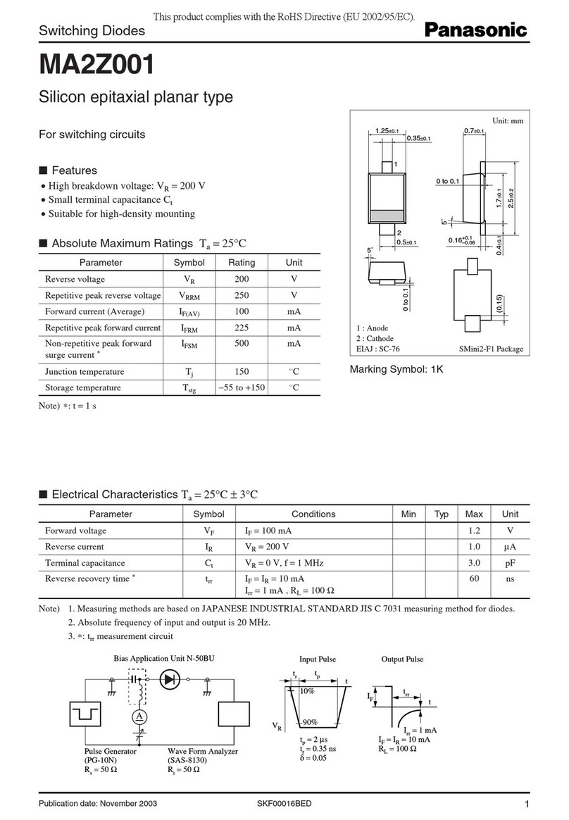
Panasonic Switching Diodes MA2Z001 Specifications

Cabletron Systems
Cabletron Systems CSMIM-T1 installation guide

Lilin
Lilin NVR5832 user manual
3xLogic
3xLogic VIGIL NVR-2U-64CH quick start guide
