FCC Class A Compliance
This equipment has been tested and found to comply with the limits for a Class A digital device, pursuant
to Part 15 of the FCC Rules. These limits are designed to provide reasonable protection against harmful
interference when the equipment is operated in a commercial environment. This equipment generates,
uses, and can radiate radio frequency energy and, if not installed and used in accordance with the
instruction manual, may cause harmful interference to radio communications. Operation of this
equipment in a residential area is likely to cause harmful interference in which case the user will be
required to correct the interference at his own expense.
Limited Warranty
Product warranty is determined by your service agreement. Contact your sales representative or
Customer Service for details.
Modifications
Any changes or modifications made to this device that are not expressly approved by ADC
Telecommunications, Inc. voids the user's warranty.
All wiring external to the products should follow the provisions of the current edition of the National
Electrical Code.
Standards Compliance
This equipment has been tested and verified to comply with the applicable sections of the following
standards:
❑GR 63-CORE - Network Equipment-Building System (NEBS) Requirements
❑GR 1089-CORE - Electromagnetic Compatibility and Electrical Safety
❑Binational standard, UL-60950/CSA C22.2 No. 60950-00: Safety of Information Technology
Equipment.
Trademark Information
ADC and Soneplex are registered trademarks of ADC Telecommunications, Inc. Other product names
mentioned in this installation guide are used for identification purposes only and may be trademarks or
registered trademarks of their respective companies.
Copyright Information
© 2004 ADC Telecommunications, Inc. All rights reserved. Information contained in this document is
company private to ADC DSL Systems, Inc., and shall not be modified, used, copied, reproduced or
disclosed in whole or in part without the written consent of ADC.
World Headquarters
ADC Telecommunications, Inc.
PO Box 1101
Minneapolis, MN 55440-1101
USA
Technical Assistance
Tel: 800.366.3891, x73223
Tel: 952.917.3223
Fax: 952.917.3244
THE LPS-H2C-L7A
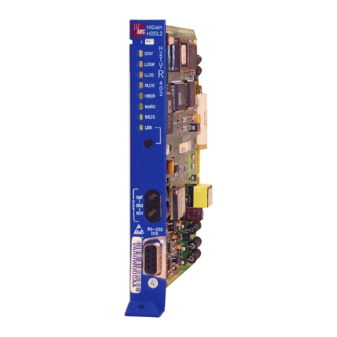
The LPS-H2C-L7A is a low-power, HDSL2 plug-in line card that installs in a
LoopStar™Chassis, Soneplex®Loop Extender Chassis (LEC), Soneplex Broadband
Chassis (BBC), or Soneplex Integrated Broadband Chassis (IBBC). To ensure proper
operation, the LPS-H2C-L7A line unit requires the H2TU-R-402-L7A as the
corresponding remote unit. The system provides 1.544 Mbps full-duplex transmission
on one unconditioned copper pair over the full Carrier Service Area (CSA) range. The
CSA includes loops of up to 12,000 feet on 24 AWG wire or 9,000 feet on 26 AWG
wire, including bridged taps.
FEATURES
SPECIFICATIONS
•1.544 Mbps full-duplex transmission on one
unconditioned copper pair
•AMI or B8ZS line code detection
•Status Light Emitting Diodes (LEDs) for Digital
Signal Level 1 (DS1) and HDSL2
•Provides -190 Vdc line power
•Ground fault detection
•Supported by Shelf Controller Unit (SCU)
software version 3.6.2 or later
•Dual loopbacks
•Lightning and power cross-protection on
HDSL2 interfaces
•AUTO, UNFR, SF, or ESF frame format
•Ultra-low wander (0.26 UI)
Operating Temperature -40°F to +149°F (-40°C to + 65°C)
Operating Humidity 5% to 95% non-condensing
Input Voltage -48 Vdc nominal (-40 to 57.5 Vdc)
Power Consumption 7.8 Watts
Line Power Output -190 ±8 Vdc
Electrical Protection Secondary surge and power cross-protection on all HDSL2 ports
Mounting LoopStar, Soneplex Loop Extender, Soneplex Broadband Chassis, or
Soneplex Integrated Broadband Chassis
HDSL2 Line Code 16 level PAM (OPTIS)
HDSL2 Output +16 dBm ±0.5 dBm, 135Ω
HDSL2 Maximum Insertion
Loss
35 dB @ 196 kHz
DS1 Equalization 0 to 655 feet in 133 foot increments
DS1 Line Rate 1.544 Mbps ±200 bps
DS1 Line Format Alternate Mark Inversion (AMI) or Bipolar 8-Zero Substitution (B8ZS)
DS1 Frame Format Extended SuperFrame (ESF), SuperFrame (SF), UNFR, or AUTO
(detects and adapts current frame format)
INSTALLATION
1Align the line card with the enclosure slot guides and slide the card in until it
touches the backplane connector.
2Raise the extraction lever at the bottom of the front panel to press the card into the
backplane connector.
POWER-UPSEQUENCE
When the line card powers up, the following occurs:
1The STAT LED briefly turns red then yellow, indicating that the power is on and
self-test is beginning. The remaining LEDs momentarily turn yellow, then turn off.
2The front-panel LEDs appear as follows upon successful completion of self-test
(refer to Table 1):
•STAT— Displays green
•RMT ALM—Off
•LPBK—Off
•DS1 LOS/BER—Off, red, or yellow (see Table 1 for detailed information).
•HDSL2 CONT/SNR—Initially displays red, then Off.
•HDSL2 LOSW/BER—Initially displays red, then displays flashing green
until loops are synchronized.
Continued Ä
´,wO¶3ƨ
1287473
March 15, 2004
Product Catalog: LPS-H2C-L7A
CLEI: SOC3FGSD
Document: LTPS-QI-8067-02
QUICK INSTALLATION
LPS-H2C-L7A LINE UNIT
