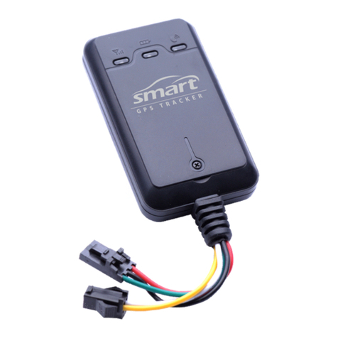
Teltronika FMB920 User manual

Instruction
assembly
FMB920 GATE CONTROL MODULE
v 6/22/20
WARNINGS
Please read this manual before proceeding with the installation. All connection
operations must be performed without the power supply connected. For security
reasons, the module should be installed by specialists with appropriate qualifications.
It is not allowed to interfere with the structure or carry out independent repairs.

1. LIST OF DEVICES
Gate power
List of devices necessary for assembly:
230V*
1. FMB920 Gate Control Module
2. 12VDC power supply (Mean Well HDR-15-12)
3. Electromagnetic relay RELPOL RM84-2012-35-1012 (socket for RELPOL GZS-80
relay)
4. Kit housing (ELEKTRO-PLAST OH-1B.1)
5. SPAMEL LK\269 limit switch (one or 2 pcs. depending on the user's requirements
regarding information on the gate status) - optional
12-24VDC
1. FMB920 Gate Control Module;
12-24VAC*
1. FMB920 Gate Control Module;
2. Electromagnetic relay RELPOL RM84-2012-35-1012 (socket for RELPOL GZS-80
relay)
3. Power converter from 24VAC to 12VDC ACTii AC1628 (optional);
4. Kit housing (ELEKTRO-PLAST OH-1B.1)
5. SPAMEL LK\269 limit switch (one or 2 pcs. depending on the user's requirements
regarding information on the gate status) - optional
* no additional devices can be purchased from Treesat except for the FMB920 gate control module.
2. DESCRIPTION
To meet the expectations of the dynamically changing market of mobile services, Treesat Sp. z o. o.
created the Click2open product. It allows remote control of home automation from anywhere in the
world via smartphone. The Click2open system will open gates, garages, barriers, wickets, vehicles, and
all kinds of locks.
The module works with the Click2open application, which can be downloaded for free from the App
Store and Google Play. The Click2open application allows you to easily share control with your loved
ones, contractors, couriers, etc. The indicated person (via telephone number or e-mail address) is
granted access, and the time of access is specified.
3. START-UP
1. Please refer to the user manual.
2. Install the application and register your account.
3. Add your device by entering your device details into the app.
4. Have the device connected by a qualified specialist.
5. Check the operation of the device by reading the behavior of the LEDs in the device:
- LED blinks every second - normal operation, GSM signal has been stabilized,
- LED flashes quickly for a short time - GSM is sending data to the server,
- Continuous blinking of the diode - the device is being updated,

- The LED is off – the GSM modem is faulty.
6. The device is ready for operation - check the possibility of controlling the gate in the
application.
7. Contact an employee via the hotline who will verify the correctness of the assembly
(and will provide a verification code to be entered in the assembly report)
4. ASSEMBLY OF THE DEVICE
Attention! Install the FMB920 module away from metal elements, with the
printed side facing the outside of the housing.
TECHNICAL SPECIFICATION of the FMB920 module
●Quad band 850/900/1800/1900MHz
●GPRS class 12 , SMS (text/data)
●1 gate control output
●2 gate position inputs
●Internal high-gain GSM antenna
●2 device status LEDs
●Power supply 6-30VDC ~250mA
●Integrated 170 mAh Li-Ion backup battery
●Operating temperature: -40 °C to +45 °C
●Humidity: 5% to 95%
●Dimensions: L(79mm) x W(43mm) x H(12mm)
●IP54

Pinouts :
Color
Destiny
Installation tips
Red
Powering the device
Connect to a permanent power supply of 6-30VDC 1A
Black
Device weight
Connect to ground
Yellow
DIN1
Gate open signal (0-30V, high detected)
Gray
AIN1
Closed gate signal (0-30V, high detected)
White
DOUT1
Gate control signal (ground control, NO output)
Before installation, check the supply voltage available in the gate
controller, it is possible that you will need additional accessories that are
not included with the device!
The FMG920 module can be connected to the controlled device in three ways:
A. Using an additional 230V 1.25A power supply and an additional control relay - the
preferred method is completely isolated from the controlled device,
B. If we do not have 230V available, and 24VAC is available, then using a 24VAC->12VDC
voltage converter and an additional control relay,
C. If we do not have 230V available and the controlled device is powered by 12-24VDC, we
can connect it directly (without a power supply/converter and an additional relay).
For each type of installation, we suggest setting the option of automatic closing of the
gate after a certain time!
4A. BASIC CONNECTION DIAGRAM, WHEREVER 230V VOLTAGE
IS AVAILABLE
This connection scheme requires additional devices (12V power supply and gate opener relay,
possibly optional status switches) which are not included in the kit. The diagram below shows the
preferred connection of the Click2open FMB920 module to the gate control panel.

In the case of gate control only, it is required to connect the relay shown in the diagram above
(not included in the set).
The dotted lines indicate the possibility of obtaining optional information about the position of
the gate (open, moving and closed) - this option requires additional limit switches that are not
included in the set.
Connect the closed gate limit switch to the gray FMB920 wire, and connect the open gate limit
switch to the yellow FMB920 wire. We can also connect only one signal, e.g. a closed gate - in this
case we lose information about the gate movement, which will be displayed as an open gate.
After installation, provide information about whether both limit sensors are connected (if one,
which one) to the person adding the device in the application in order to properly set the limit
switch options. In the application, it is possible to negate the signals from the limit switches if an
incorrect gate status is displayed.

4B . _ EXAMPLE DIAGRAM CONNECTION IF WE DO NOT
HAVE 230V AVAILABLE AND 12-24VAC IS AVAILABLE
This connection scheme requires additional devices (12VAC-24VAC to 12VDC Converter and gate
opener relay, possibly optional status relays) which are not included in the kit.
The diagram below shows an example of connecting the Click2open module (FMB920) with the
gate control panel, only if there is no 230V voltage available and the controller has an output for
12VAC-24VAC accessories.
Before connecting the converter, make sure that the available power supply of the accessories in
the gate control unit has the appropriate current capacity for the FMB920 and the gate control
relay.
The dotted lines indicate the possibility of obtaining optional information about the position of
the gate (open, moving and closed) - this option requires additional limit switches that are not
included in the set.
Connect the closed gate limit switch to the gray FMB920 wire, and connect the open gate limit
switch to the yellow FMB920 wire. We can also connect only one signal, e.g. a closed gate - in this
case we lose information about the gate movement, which will be displayed as an open gate.

After installation, provide information about whether both limit sensors are connected (if one,
which one) to the person adding the device in the application in order to properly set the limit
switch options. In the application, it is possible to negate the signals from the limit switches if an
incorrect gate status is displayed.
4C. EXAMPLE OF CONNECTION DIAGRAM IF 230V VOLTAGE IS
NOT AVAILABLE AND 12-24VDC IS AVAILABLE
Attention! Connection does not require any additional accessories. FMB920 is connected directly
to the gate controller.
Before connecting, check whether the accessory power supply output has sufficient current
capacity (min. 12VDC 250mA). The White wire should be connected to the gate control terminal
(1). Optional features are marked with dashed lines. They make it possible to obtain information
about the state of the gate position (open, in motion and closed). These functions require
connection in accordance with the above diagram, signals from the gate limiters, sometimes

signaling lamps or adding additional limit switches if they are not led out to the connection strip
in the gate control panel. We connect the signal to the gray FMB920 wire when the gate is closed,
and to the yellow FMB920 wire we connect the signal when the gate is open.
After installation, provide information about whether both limit sensors are connected (if one,
which one) to the person adding the device in the application in order to properly set the limit
switch options. In the application, it is possible to negate the signals from the limit switches if an
incorrect gate status is displayed.

5. APPLICATION
Click2open App Download
The Click2open application for Google Android can be downloaded from the Google Play
store, and for Apple iOS - from the Apple iTunes Store. Using the appropriate reader on your
phone, use the link in the QR code. The selection page will open.
Requirements
For the correct operation of the application, a mobile device (smartphone, tablet) with the
Google Android operating system version 6.0 or higher or an Apple mobile device with the
Apple iOS operating system version 11 or higher is required.
6. EXAMPLES OF CONTROL TERMINAL DESIGNATIONS OF POPULAR
GATE AUTOMATION MANUFACTURERS
Producer
Gate control
terminals*
Gate status information terminals
(closed/open)
Nice ROX600
"9" and "13"
Additional optional limit switches
Came BX-74
"2" and "7"
Additional optional limit switches
Beninca Bull 5
"COM" and "PP"
Additional optional limit switches
Faac 740
“Open A” and “-”
Additional optional limit switches
Electrobeam
KSE180
"9" and "5"
Additional optional limit switches
Life RG DL
"6" and "10"
Additional optional limit switches
BFT DEIMOS
BT MA
“OPEN” and “COM”
Additional optional limit switches
Summer
Starter+
"2" and "3"
Additional optional limit switches
Wiśniowski
AWSo2018
“OPEN” and “GND”
Additional optional limit switches
* The information presented above regarding the gate control terminals are only indicative data and require verification with the
installation manual provided by the manufacturer of the automatic machine. Treesat is not responsible for damage caused in
case of incorrect connection of the device.

7. MARKINGS
Treesat Sp. z o. o. has used all the possibilities available to it to provide the most up-to-date
information about its products. Treesat Sp. z o. o. makes no warranties related to the content
of this manual and disclaims any implied warranties regarding its market value or suitability
for specific purposes. The information contained herein serves as guidance for the use of the
device. Treesat Sp. z o. o. reserves the right to make corrections, changes or translations of
the User's Manual without prior notification of such changes. It is therefore recommended
that you visit our website regularly for the latest information.
Treesat Sp. z o. o. is not responsible for damages resulting from improper use of the
Click2open system and incorrect installation of the control module. Before installing the
device, check whether the gate manufacturer allows the installation of external devices. The
warranty for additional accessories (such as power supplies, handles, cables) and
consumables (non- rechargeable batteries and accumulators) is 6 months for both consumers
and traders from the date of purchase.
After the expiry of any annual package, the user must purchase a new package within 30 days
via the application or panel. If the package is not purchased, the SIM card is deactivated.
Reactivation of the device will involve the user incurring the costs of SIM replacement and its
reactivation.
Warning risk of electric shock - do not open. This inscription warns
against opening the receiver housing. Only authorized service
personnel are allowed to open the housing.
CE mark. This marking informs that the device complies with the
provisions of Directive 2004/108/EC concerning the observance of
electromagnetic compatibility regulations by Member States and the
conditions of Directives 2006/95/EC concerning compliance with low
voltage regulations and safety related to the operation of electrical
equipment by Member States.

The symbol of the crossed-out waste bin attached to the product
means that the product is covered by the European Directive
2002/96/EC. Information on separate collection points for waste
electrical and electronic products can be obtained from the place of
residence. Please follow the guidelines of your local authorities and
do not dispose of this type of equipment with other household waste.
The correct disposal of your old products helps prevent
environmental pollution and loss of health.
If this logo is found on the product, it means that the fees related to
the appropriate recycling and recovery system have been paid.
This logo informs that the device is compliant with the terms of
Directive 2011/65/EU (commonly known as the Restriction of
Hazardous Substances Directive or RoHS). The RoHS directive covers
restrictions at the production stage in the introduction of hazardous
substances in electronics.
Table of contents
Other Teltronika GPS manuals
