Telular Phonecell SX3i AMPS User manual
PHONECELL SX3iAMPS
F
IXED
W
IRELESS
T
ERMINAL
USER MANUAL
Total communications freedom at your
fingertips...voice/fax/data.
12/08/99 Part No. 56016602
PHONECELL SX

Introduction
PHONECELL SX3i AMPS 2USER MANUAL 12/08/99
Phone(s)
Fax Machine
AC Power
Computer
Modem
l
l
PHONECELL SX
Thank you for choosing the Phonecell®SX3 Fixed Wireless Terminal (FWT) from
Telular. This innovative product lets you connect up to five pieces of standard tele-
phone equipment into a cellular network for total communications flexi ility.
Please follow this guide to unpack, set up and operate your new Phonecell
safely and properly.
Telular is proud to welcome you as a valued customer.
Your satisfaction is our most important concern.
Telular Corporation
Corporate Head uarters
647 North Lakeview Parkway
Vernon Hills, Illinois 60061, USA
TECHNICAL SUPPORT
Tel: 847-247-9400 · Fax: 847-247-0021
E-mail: mainoffice@telular.com · http://www.telular.com
Patents: Telular Corporation products are protected and manufactured under
one or more of the following U.S. patents and related
international patents and patents pending relating thereto:
4,658,096; 4,737,975; 4,775,997; 4,868,519; 4,922,517; 5,134,651;
5,361,297; 5,469,494; 5,046,085; 5,715,296; 5,812,637; 5,859,894;
5,946,616; 5,966,428; 6,035,220.
Trademarks: Telular Corporation owns the following registered trademarks:
TELULAR, TELULAR plus design, CELJACK, PCSone, TELCEL, HEXA-
GON LOGO, PHONECELL, CELSERV, TELGUARD, and CPX.
Part No. 56016602 ©2000 Telular Corporation, all rights reserved.

PHONECELL SX3i AMPS 3USER MANUAL 12/08/99
Table o Contents
Introduction...............................................................................................2
Technical Support ...................................................................................2
Getting Started
Unpacking the Phonecell SX3i ...............................................................4
Pre-Installation Checklist ........................................................................4
Installation Summary ...............................................................................5
Step 1. Choose an Antenna Location.....................................................6
How to Connect the Antenna .................................................................7
Step 2. Plug in Your Telephone ...............................................................8
Connect Your Telephone ........................................................................8
Place a Call Adjust Your FWT .............................................................8
Connecting Additional Phones & Equipment..........................................8
Step 3. NAM/Phone Number Setup....................................................9-11
Optional A-Key (Authentication Code) Setup .......................................11
Step 4. Optional Battery Installation ...............................................12-13
Step 5. Install Your Phonecell
Wall-Mount Installation .........................................................................14
Desktop/Ta letop Installation................................................................15
Phonecell SX3i Operation
How to Use the LED Status Indicator...................................................16
How to Place a Call..............................................................................16
How to Receive a Call..........................................................................16
How to End a Call ................................................................................16
The Hookflash Function .......................................................................16
Important Tones and Alerts...................................................................17
How to Adjust the Volume Level...........................................................17
Fax/Data Transmission.........................................................................17
Varia le Dial Time (Auto SEN elay) Option.....................................18
Special Cellular Services.................................................................18-19
Data After SEND (In-Call TMF Signaling) Option ..............................19
Zero Dial Delay for Frequently Called Num ers ..................................19
Phonecell SX3i Troubleshooting...........................................................20
Safety Information.............................................................................21-23
AMPS Technician Programming
How to Enter the Programming Mode..................................................24
How to Set the Access Overload Class (ACCOLC) .........................25
How to Set the Access Method (EX) Option ....................................25
How to Set the Roam Option............................................................25
How to Set the Dial Tone After Remote On-Hook Option ................25
How to Set the Post-Receiver Off-Hook (ROH) Option....................26
How to Set the Pulse Dial Option .....................................................26
How to Initiate a Ring-Back Request................................................26
How to Restore the Factory Default Settings ...................................26
How to Ena le/Disa le the Zero Dial Delay Option .........................26

PHONECELL SX3i AMPS 4USER MANUAL 12/08/99
Getting Started...
Pre-Installation Checklist
Before attempting Phonecell SX3i installation, make sure you have the
following components, tools and materials.
Qty. Description Supplied Not Supplied
1 Antenna (Spike, Magnetic-Mount, or Yagi) 4
2 6-Volt, 4.5 AH Lead-Acid Batteries (Optional 4
for Battery Backup)
1 RJ-11 Modular Phone Cord (Length varies 4
according to your specific installation and
the number of phones you plan to connect)
1 RJ-11 Phone Line Splitter (if you plan to 4
connect more than one telephone device)
Components Needed
Tools & Materials Needed for Wall-Mount Installation Only)
Qty. Description Supplied Not Supplied
1 Drill & Drill Bit 4
1 Screwdriver 4
21
1/2-inch (3.75 cm) Mounting Screws 4
Un-Packing Your Phonecell SX3i
The Phonecell SX3i comes with the following:
ÊPhonecell SX3i Fixed Wireless Terminal (FWT)
ËAC Power Cord
ÌDrill Mounting Template
ÍThree Ru er Feet for Desktop/Ta letop Use*
(* o not attach feet if wall-mounting the FWT.)
Carefully remove the unit from the shipping carton and check for evidence
of shipping damage. If damage is found, contact your Authorized
Telular Distributor or shipping agent immediately.
ÊÌÍ
Ë
PHONECELL SX
Installation Summary
PHONECELL SX3i AMPS 5USER MANUAL 12/08/99
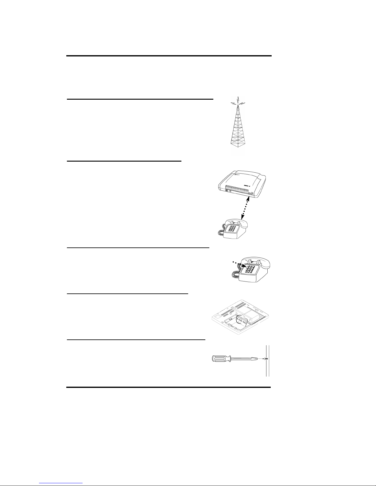
Step 1. Choose an Antenna Location pg. 6-7)
··Choose a location.
··Next, connect power to the FWT.
··Then, connect the antenna (not supplied).
··Check the cellular signal strength and
move the antenna until you achieve the
est signal possi le.
Step 2. Plug In Your Phone page 8)
··Once the antenna is connected, hook up
a phone.
··Then, make a test call to check noise levels,
and adjust the antenna location accordingly.
··NOTE: If your Phonecell SX3i is not pre-pro-
grammed for NAM (Number Assignment Module)
information, youll need to perform the
NAM/Phone Num er Setup in Step 3. Then, return
to this step (2).
··Plug in additional phones, Fax and/or Modem.
Step 3. NAM/Phone Number Setup pg. 9-11)
··If your Phonecell was not pre-programmed for
NAM information, you need to perform the
NAM/Phone Num er Setup procedure.
··Otherwise, continue to Step 4.
Step 4. Battery Installation pg. 12-13)
··Follow these instructions to install optional at-
teries (not included) for ackup in the
event of AC power failure.
··Otherwise, continue to Step 5.
Step 5. Wall or Desk Installation pg. 14-15)
··After youve selected a location and made all
the necessary connections and adjustments,
your Phonecell SX3i is ready for either
wall-mounting or desktop/ta letop use.
There are five steps to installing the Phonecell SX3i FWT properly.
These steps are summarized elow and explained in detail in the
remainder of this manual.
F

PHONECELL SX3i AMPS 6USER MANUAL 12/08/99
Step 1. Choose an Antenna Location
Your Phonecell SX3 receives operating commands from the cel-
lular network and relies upon signal strength for proper opera-
tion. Therefore, finding an antenna location with good signal
strength is critical for call quality.
A
NTENNA
L
OCATION
T
IPS
:
··Locate the antenna above ground and as close
to windows (or exterior wall ) as possible see
Fig. 1.
··Try to install the antenna in an uninhabited area
(i.e. clo et , attic , etc.) to ensure a minimum
separation of 16 inches (40 cm) between the
antenna and the inhabitants.
··In low signal areas, the antenna should be
mounted on the buildings exterior see Fig. 2.
··igh-gain (Yagi) antennas must be directed
toward your service providers nearest cellular
tower.
··Spike antennas must be pointed upward.
··Keep antenna cable as short as possible long
cable runs affect call quality.
··Never splice antenna cable.
Fi . 2 Optional high-gain antenna installed on the buildings exterior. Always
direct the antenna toward the nearest cell tower of your service provider.
Fi . 1 Optional spike antenna point-
ed upward and located near the win-
dow for optimum signal strength.
Coaxial Cable

PHONECELL SX3i AMPS 7USER MANUAL 12/08/99
WARNING!
Never operate your Phonecell
when any person is within 16
inches (40 cm) of the antenna.
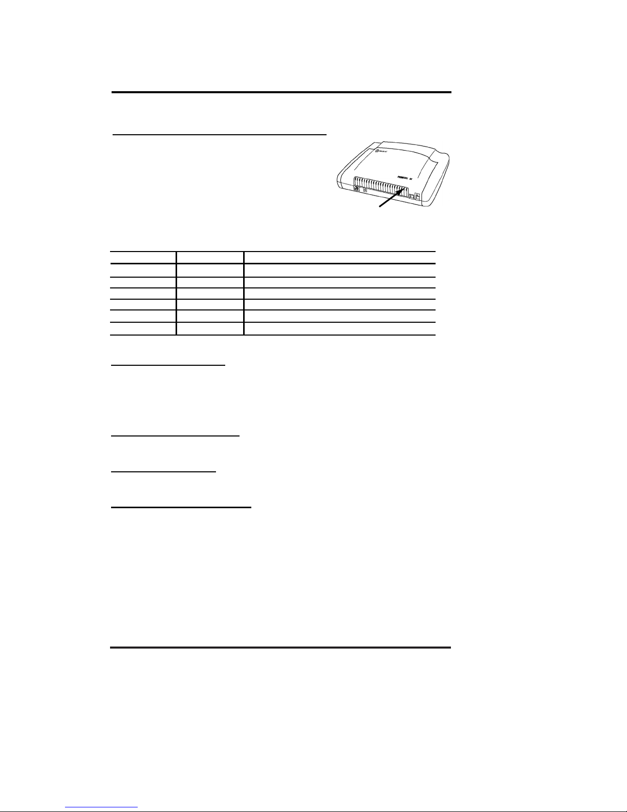
How to Connect the Antenna:
1) Connect the AC line cord from the
power port on the front of the FWT
to the AC power source see
Figure 3.
OR if an external DC power source
is used, connect an optional DC
input ca le to the DC Input port.
2) Turn on the FWT power using the
power switch. After approximately
10 seconds, the LED indicator on
the front of the FWT should turn
RED.
3) Connect an antenna to the TNC
antenna connector on top of the
FWT see Figure 4.
4) Move the antenna from one location
to another until you achieve the est
signal strength possi le.
Test the cellular signal strength
by checking the LED indicator
on the front of your Phonecell:
·· Solid RED = No Service
··Solid YELLOW = Moderate
signal strength
··Solid GREEN = Good signal
strength.
5) When youre getting a strong
(GREEN) signal, youre ready
for the next step connecting
a phone and making a call.
Antenna Location & Setup Continued
A
NTENNA
T
IP
:
Many things can obstruct the cellular
signal, and moving the antenna as little as
one meter (3 feet) can dramatically
improve signal strength and call reception.
!
AC Power
AC Port
LED
Indicator
Fig. 3
l
l
AC Line
Cord
Power
Switch DC Port
Optional
Ma netic-
Mount
Optional
Spike
Optional Hi h-Gain
TNC Antenna
Connector
Fig. 4
PHONECELL SX
LED
Indicator
Power
Switch
PHONECELL SX3i AMPS 8USER MANUAL 12/08/99
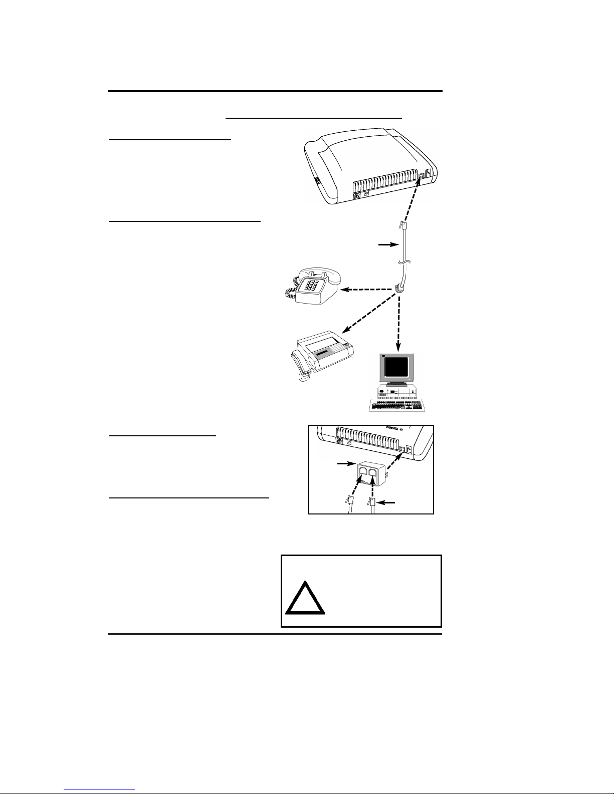
Step 2. Plug In Your Telephone
Your Phonecell SX3 lets you connect up to 5 pieces of standard telephone equip-
ment into a cellular network. Follow the steps elow for quick installation.
Connect Your Telephone:
1) Locate the modular (RJ-11) line port
on your phone and plug in one end of
a standard (RJ-11) phone cord.
2) Connect the other end of the cord
to the RJ-11 port on the front
of your Phonecell SX3i see Fig. 5.
Place a Call Adjust Your FWT:
1) Pick up the phone receiver and listen
for dial tone.
2) If you hear dial tone, make a call.
3) While youre talking with the other
party, listen for static and echo. If you
hear either, move the antenna until
you find the spot where voice conver-
sation is strong, and static
and echo are minimized.
NOTE: If you are unsuccessful in
dialing out, verify the following:
··The antenna location needs to e
adjusted see Step 1, page 6-7.
··The NAM/Phone Num er needs to
e set up see Step 3, page 9-11.
··Your cellular phone num er has not
een activated contact your cel-
lular service provider.
Adding More Phones?
Plug in an RJ-11 line splitter (not sup-
plied) to connect additional phones to
your FWT see Fig. 6. NOTE: you can
only make one phone call at a time.
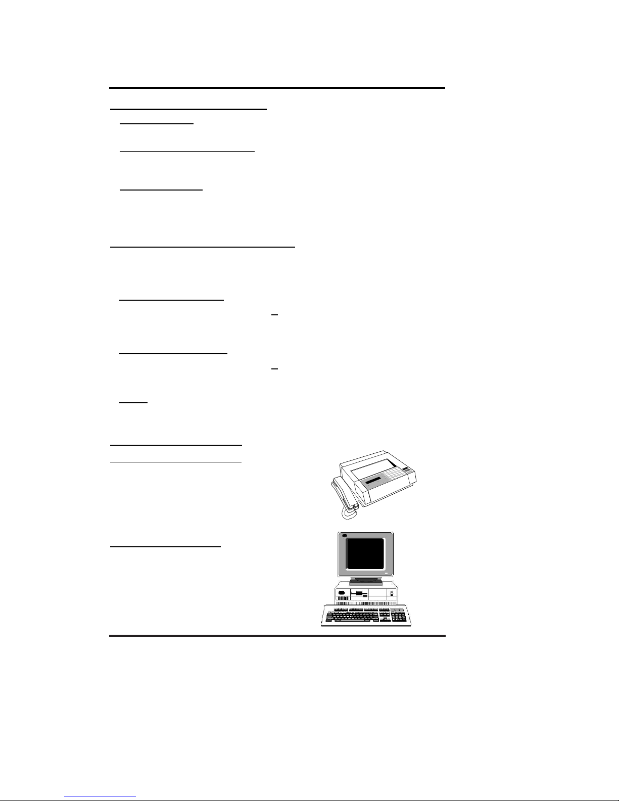
Additional Telephone Equipment:
If you plan to use a device other than a
telephone with your Phonecell SX3 (such
as a modem), make sure that device will
work with a normal wired telephone line.
Fax Machines Connect a fax machine
the same way it needs to e set up for
use on a regular wired telephone line.
PBX/KSU Systems PABX
installation should only be performed
by experienced telephone technicians.
IMPORTANT!
Make sure the wiring from the
telephone equipment to your
Phonecell SX3 is properly
protected from all transient
voltages, including lightning.
!
Phone
Cords
Line
Splitter
Fi . 6 Optional RJ-11 Line Splitter
lets you connect additional phone
equipment to your Phonecell SX3i.
To Fax
To Phone(s)
Phone Cord
To
Modem
To RJ-11 Port
RJ-11
Port
Fig. 5

PHONECELL SX3i AMPS 9USER MANUAL 12/08/99
Step 3. NAM/Phone Number Setup
You can program the Phonecell SX3 with an ordinary tone-dial ( TMF) telephone,
which is sometimes referred to as a POTS (Plain Old Telephone Service) phone.
NOTE: this programming mode is not accessible while you're in a call.
Step #1 - Pick up the POTS handset and listen for a tone (either a steady dial
tone or a beeping no-service tone).
Step #2 - Enter the Master-Programming mode y pressing:
#*0 *1 2 3 4 4 3 2 1 #
The dial tone should change to a different, steady Programming tone
and the LED indicator on the front of your Phonecell should link
alternately RED and GREEN to indicate that youre now in the
programming mode. You now have two minutes to begin the
programming steps below.
Step #3 - Press: #*1 *_ _ _ _ _ _ _ _ _ _ #
The spaces represent your 10-digit telephone num er. (This is also
called a Mobile Identification Number, or MIN.) If you enter the num er
incorrectly, you'll hear three short tones followed y the programming
tone; if correct, you'll hear the programming tone again.
Step #4 - Press: #*5 *_ _ _ _ _ #
The spaces represent your 1- to 5-digit System Identifier (SID), which
ranges from 0to 32,767. This information identifies your cellular serv-
ice provider. (For example, to set up 555, enter #*5*555#.) If you enter
the SID incorrectly, you'll hear three short tones followed y the pro-
gramming tone; if correct, you'll hear the programming tone again.
NOTE: depending upon whether you enter an odd SID or an even SID,
the Phonecell will automatically set the remaining NAM parameters to
AMPS standards as shown in the table below.
If you need to override any of the settings, continue with steps 5 - 8.
Otherwise, hang up. The flashing LED indicator will ecome solid
GREEN. Phone number setup is complete.
F
F
F
Continued...
IMPORTANT!
If your Phonecell was NOT pre-programmed for NAM (Number
Assignment Module/Phone Number) information, follow the
steps below. Otherwise, continue to STEP 4, pages 12,13.
!
AMPS Standards
Automatically Set NAM Parameters Odd SID Even SID
Initial Dedicated Control Channel 333 334
First Paging Channel 333 334
Num er of Dedicated Control Channels 21 21
Preferred System AB
Roam Option (to override, see page 25) Enabled Enabled

PHONECELL SX3i AMPS 10 USER MANUAL 12/08/99
NOTE: The following NAM Parameters are automatically set y the SID value in
step 4 on the previous page. These steps 5 - 7 are only needed if you want to
override the standard AMPS settings listed on the previous page. Otherwise,
continue to Step 4 Optional Battery Installation on pages 12,13.
Step #5a - How to Override the Initial Dedicated Control Channel and First
Paging Channel.
If you have an A cellular service provider with an odd SID
System Identifier), enter the following 2-part key se uence.
Otherwise, continue to Step #5b.
1) First press: #*24 *_ _ _ _ #
2) Next press: #*4 *_ _ _ _ #
Note: enter the same 1- to 4-digit channel in both steps above.)
The spaces represent your 1- to 4-digit Initial Dedicated Control
Channel and First Paging Channel. When you turn on your Phonecell,
these channels help the service provider find you and vice-versa.
NOTE: The default setting is channel 333 for "A" service providers. To
change the setting, you must enter a 1- to 4-digit num er in the range
of 0 to 1023.(For example, to set up channel 565, enter #*24*565#.) If
you enter the channel incorrectly, you'll hear three short tones followed
y the programming tone; if correct, you'll hear the programming tone
again.
Step #5b - If you have a B cellular service provider with an even SID
(System Identifier), enter the following 2-part key se uence.
1) First press: #*25 *_ _ _ _ #
2) Next press: #*4 *_ _ _ _ #
Note: enter the same 1- to 4-digit channel in both steps above.)
The spaces represent your 1- to 4-digit Initial Dedicated Control
Channel and First Paging Channel. When you turn on your Phonecell,
these channels help the service provider find you and vice-versa.
NOTE: the default setting is channel 334 for "B" service providers. To
change the setting, you must enter a 1- to 4-digit num er in the range
of 0 to 1023.(For example, to set up channel 566, enter #*25*566#.) If
you enter the channel incorrectly, you'll hear three short tones followed
y the programming tone; if correct, you'll hear the programming tone
again.
F
F
NAM/Phone Number Setup Override Commands
F
F
Continued...

Step #6 - How to Override the Number of Dedicated Control Channels.
Press: #*26 *_ _ #
The spaces represent your 2-digit range of Dedicated Control
Channels. When you first turn on the Phonecell, it automatically scans
up to 21 control channels looking for your cellular provider. Then, it
locks onto the strongest signal. NOTE: the factory default setting is 21
channels. T
o change the num er of channels, you must enter a 2-digit
value in the range of 01 to 21.(For instance, to set up 9 control chan-
nels, enter: #*26*09#.) If you enter the range incorrectly, you'll hear
three short tones followed y the programming tone; if correct, you'll
hear the programming tone again.
Step #7 - How to Override the System Preference.
Press: #*7 *_ #
The space represents your 1-digit system preference.
enter: 0for System A preferred
enter: 1for System B preferred
enter: 2for System A only
enter: 3for System B only.
This sets the preference for your cellular provider. If you enter the pref-
erence incorrectly, youll hear three short tones followed y the pro-
gramming tone; if correct, youll hear the programming tone again.
Step #8 - Hang up. The flashing LED indicator will ecome solid GREEN.
Phone number setup is complete.
F
F
F
F
F
F
NAM/Phone Number Setup Override Commands
PHONECELL SX3i AMPS 11 USER MANUAL 12/08/99
Optional A-Key Authentication Code) Programming
Depending upon your cellular service provider, you may e required to enter an
Authentication Code (A-Key) efore you make or receive any calls. Contact your
service provider to determine whether A-Key is required.
The A-Key is a cellular system solution to prevent cloning, counterfeiting and cel-
lular fraud. Its a unique, 6- to 26-digit code provided y your service provider that
validates your MIN (Mobile Identification Number) and ESN (Electronic Serial
Number) efore you make or receive calls. Once youve entered the A-Key, your
Phonecell automatically verifies the code with the cellular provider efore every
call. Theres no need to re-program the unit, unless you switch to a new service
provider or change your MIN.
Use the following key sequence to program the A-Key:
Press: #*27 *<A-Key> #
The < > rackets represent your 6- to 26-digit A-Key (Authentication
code), which is supplied y your cellular service provider.
F
IMPORTANT!
For security reasons, your complete A-Key is never transmitted
over the phone. However, you should keep the number in a
safe place to prevent counterfeiting, fraud or cloning.
!

PHONECELL SX3i AMPS 12 USER MANUAL 12/08/99
1) Make sure that the switch is in the off
position.
2) Disconnect AC and/or DC power cord(s).
3) Locate the attery compartment, which is
next to the silver transceiver on the ack
of the FWT -- see Figure. 7.
NOTE: Make sure that the power switch is
in the OFF position.
4) Remove the attery compartment cover y
pressing the securing ta downward while
sliding the lid toward the securing ta .
5) Position the Phonecell so that the attery
compartment is closest to you and the sil-
ver transceiver is furthest away from you.
6) Place an insulator (i.e. paper or
plastic) etween the atteries and
silver transceiver -- as shown in
Figure 8. This will prevent the
atteries from damaging the
Phonecells transceiver.
Step 4. Optional Battery Installation
DANGER!
Follow these instructions exactly. If the wire leads are not connected
to the proper terminals, the circuit board and/or transceiver may be
damaged. Always observe proper polarity (make sure the colored
wires match) while installing the wire leads and connecting wire.
!
Your Phonecell SX3i has an internal power supply with attery ackup that pro-
vides uninterrupted talk time and stand y operation in the event of AC power
failure. The power supply will trickle-charge the atteries while AC power is
availa le. However, no recharging occurs during conversation mode.
The FWT uses two 6-Volt (4.5 Amp. Hr.) atteries (not supplied). Batteries are not
shipped in the unit to prevent damage and to avoid power draining. To install bat-
teries, turn the Phonecell upside down and follow the instructions below:
Battery
Compartment
Fi . 7
CAUTION!
o Not allow the battery terminals to touch the silver transceiver
at any time, under any circumstances.
!
Battery
Compartment
Transceiver
Batteries
Fi . 8
Continued...
Power
Switch
PHONECELL SX3i AMPS 13 USER MANUAL 12/08/99
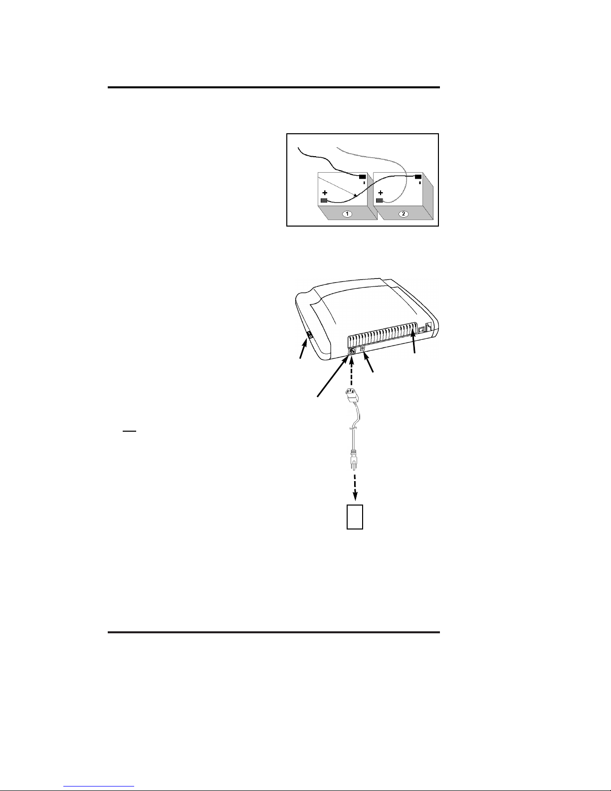
Battery Insta ation Continued
7) Connect the atteries as follows:
··Connect one end of the BLUE wire
(attached to the battery cover) to the
BLACK (-) terminal of the second
attery
··Attach the other end of the BLUE
wire to the RED (+) terminal of the
first attery as shown in Fig. 9
··Connect the BLACK wire to the
unattached BLACK (-) terminal
of the first attery
··Attach the RED wire to the unat-
tached RED (+) terminal
of the second attery.
8) Carefully lower the atteries into the
compartment as a pair, ensuring that
the wires are not pinched against the
compartment wall
or guides.
9) Once the atteries lay flat,
replace the attery compartment cover
and slide the cover closed until the
securing ta pops up. Battery
Installation is complete.
10) Re-connect the AC line cord from the
power port on the front of your
Phonecell SX3i to the power source
see Figure 10.
OR if an external DC power source is
used, re-connect the optional DC input
ca le to the DC Input port.
11)
Turn ON the Power switch. After
approximately 10 seconds, the LED
indicator on the front of the Phonecell
should turn RED, then GREEN.
NOTE: the FWT must be connected to AC
power for at least 24 hours to fully
charge the batteries before theyll
back up your Phonecell SX3i.
Fi . 9
BLACK RED
BLUE
AC Power
AC Port
DC Port
LED
Indicator
Fi . 10
l
l
Power
Switch
PHONECELL SX3i AMPS 14 USER MANUAL 12/08/99
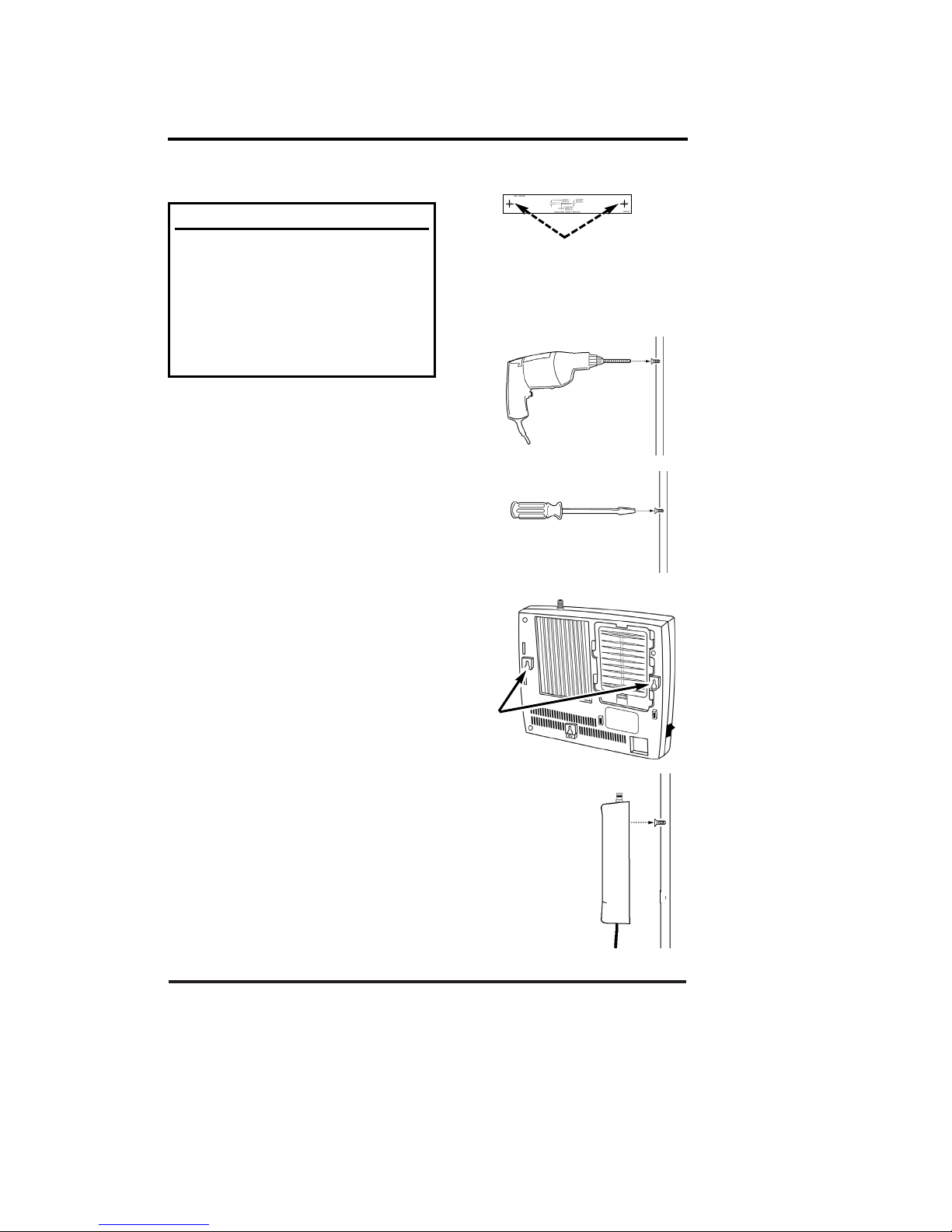
Step 5. Install Your Phonecell
5a. Wall-Mount Installation
1) Hold the mounting template against
the wall and mark two holes for the
mounting screwssee Figure 11.
2) Drill two holes for the mounting
screwssee Figure 12.
3) Install the mounting screws into the
wall, leaving a out 1/8-inch (3 mm)
gap etween the screw heads and
the wallsee Figure 13.
4) Locate the two mounting holes on
the ack of the Phonecell see
Figure 14.
5) Align the mounting holes on the
Phonecell with the two wall-mounted
screws. Then, mount the Phonecell
onto the screws and slide it down-
ward until the screw heads lock into
the mounting holes and the unit is
securesee Figure 15.
Fi . 11
After youve selected a location and made all the necessary connections,
your Phonecell SX3 is ready for wall-mounting or desktop installation.
P
RE
-I
NSTALLATION
T
IPS
:
··Make sure the location is dry, away from
overhead water pipes, and protected
from weather conditions.
··The area should be free of airborne
contaminants.
··The Phonecell should be located within
2 meters (6 feet) of an AC power outlet.
Fi . 15
Fi . 12
Fi . 13
Fi . 14
Mountin
Holes

PHONECELL SX3i AMPS 15 USER MANUAL 12/08/99
IMPORTANT!
Your Phonecell SX3 must be placed or mounted on a flat,
level surface to allow proper ventilation. o not block the air
vents or the space beneath your Phonecell as this could
cause the unit to overheat and fail.
5b. Desktop/Tabletop Installation
After all connections are made, turn your
Phonecell SX3 face-down and attach the 3
ru er feet to the ottomsee Figure 16.Your
Phonecell SX3 is now ready for use on a
desktop, ta letop or other flat surface*.
*NOTE: o not attach the rubber feet if the
unit is to be wall-mounted.
Phonece Insta ation Continued
Fi . 16
!
PHONECELL SX3i AMPS 16 USER MANUAL 12/08/99
Phonecell Operation
LED Status Table
LED Color LED Activity Description
RED Flashing Malfunction. Hardware fault detected.
RED Continuous No cellular service.
YELLOW Continuous Moderate cellular signal strength.
GREEN Continuous Best cellular signal strength.
RED/GREEN Alternating Diagnostic/programming mode.
OFF None No Power.
How to Use the LED Status Indicator
1) Plug in the AC power supply.
2) Wait approximately 10 seconds for the unit
to initialize.
3) Then, the LED indicator on the front of your
Phonecell will turn ON. The LE Status Table
elow descri es the modes and operation of
this 3-color indicator.
Once your Phonecell SX3 is installed and tested, its ready for operation.
LED Indicator
How to Place a Call
1) Pick up your telephone handset (your phone is now off-hook).
2) Listen for dial tone (If service is not available, a No-Service tone is
produced. Hang-up the phone and try again.)
3) Dial the phone num er.
How to Receive a Call
··When your telephone rings, pick up the handset and egin talking.
How to End a Call
··Hang-up the phone (place the handset back onto the telephone cradle).
The Hookflash Function
When you initiate the Hookflash function, it automatically lets you:
··Speed up the connection after you dial a phone num er.
··Answer an incoming call that occurs when youre dialing a phone num er.
··Use special (supplementary) cellular services which may e availa le
in your cellular service area (see Special Cellular Services on page 18).
How to Use the Hookflash Function
Depending upon your phone, there are two ways to initiate the Hookflash function:
··Press the dedicated HOOKFLASH or FLASH key on your telephone.
··Press the hang-up or switch-hook mechanism on your phone once quickly
(approximately 1/2-second).
PHONECELL SX3i AMPS 17 USER MANUAL 12/08/99
Phonece Operation Continued
Important Tones and Alerts
No-Service Tone When cellular service is not availa le, the receiver emits a
No-Service (fast-beeping) tone instead of the normal (steady) dial tone.
ROH (Receiver Off-Hook) Tone If the telephone equipment remains off-hook
(off its cradle) with no dialing activity for 45 seconds, the receiver emits an ROH
tone for 60 seconds.
Incoming Call Alert If youre dialing a num er and an incoming call occurs,
the receiver will emit an audi le ring. To answer the incoming call:
··Press the HOOKFLASH utton once. This will connect the incoming call.
··OR hang-up immediately. This will cause the phone to start ringing.
How to Adjust the Volume Level
If the volume level on your phone is too high or too low, you can adjust the levels
using the keypad on your telephone. Note: your telephone must be in Tone-
Dial DTMF) mode to adjust the levels.
To Increase Audio Level - Increase the audio level in steps y pressing:
F#*8(also known as #*Up)
Continue to press #*8until the desired level is reached.
To Decrease Audio Level - Decrease the audio level in steps y pressing:
F#*3(also known as #*Down)
Continue to press #*3until the desired level is reached.
NOTE: The default setting lets you adjust the audio up to three (3) steps in
either direction (Up or own).
Fax/Data Transmission
Automatic Level Setting ALS)
When your Phonecell SX3 detects a fax or
modem call, it automatically adjusts the Transmit
and Receive audio levels for optimum data
transmission. After the fax/data transmission is
completed, the Phonecell resets the audio levels
to their previous settings (patent pending).
Fax/Modem Compatibility
Your Phonecell is compati le with all Group 3 facsimile
machines and computer modems. Depending upon
the type of modem used and the cellular networks
capa ility, data transmission rates of 2400 aud and
higher are normally possi le.

PHONECELL SX3i AMPS 18 USER MANUAL 12/08/99
Variable Dial Time Auto SEND Delay) Option
When you place a call, your Phonecell SX3 automatically sends the phone num-
er over the cellular network after you dial the last digit just like a landline
phone. However, to make sure you have enough time to dial the last digit, a 3-
second Auto SEN elay is programmed into the unit. This delay also affects
Special Functions such as Call Forwarding (see Special Cellular Services below).
You can set the Auto SEND Delay from 2to 20 seconds using an ordinary tone-
dial ( TMF) phone, which is sometimes referred to as a POTS (Plain Old
Telephone Service) phone. Note: you cannot change the delay while you are mak-
ing a call.
How To Adjust the Auto SEND Delay - Pick up the telephone handset and
listen for dial tone. Then, enter the User-Programming mode y pressing:
#*0 *1 2 3 4 5 6 7 8 #
The dial tone should change to a steady Programming tone and the LED
indicator on the front of your Phonecell should link alternately RED and
GREEN to indicate that youre now in the Programming mode.
Next, press: #*11 *<Auto SEND Delay> #
The < > rackets represent the Auto SEND Delay. You must enter a value
etween 2and 20 seconds. (For instance, to enter a 5-second delay, press:
#*11*5 #.)
If you enter the delay incorrectly, youll hear three short eeps followed y the
programming tone. That is your cue to re-try the steps a ove. If correct, youll
hear the programming tone again. Hang up. Your Phonecell is ready for use.
Special Cellular Services
Your Phonecell SX3 is compati le with a variety of special services such as call
forwarding, call waiting, and more. Depending upon your cellular provider, these
services may e availa le on a su scription asis. However, certain dialing
sequences must e entered, which vary among service providers. Please consult
your service provider for the dialing instructions for your system.
Call Forwarding After you hear a dial tone on your telephone handset, dial the
code required y the service provider, wait for a minimum of 3seconds or press
the HOOKFLASH.* Your Phonecell automatically transmits the call-forwarding
information. Listen for the cellular carrier response. Then, hang up the phone. If
you dont wait for the response, your forwarding request may not e fulfilled.
*You can set this delay for 2to 20 seconds. See the Variable ial Time section
above. NOTE: please wait 1second longer than the delay programmed (i.e. for
the 3-second delay mentioned above, wait 4seconds).
Call Waiting If your cellular provider requires codes to e entered involving dig-
its 1-9, *, and #to answer a waiting call, the Out-of-Band Signaling option must e
ena led. See the ata After SEN option on page 19.
Phonece Operation Continued
F
F

PHONECELL SX3i AMPS 19 USER MANUAL 12/08/99
Three-Way Conference Calls - For three-way conference calls, the Out-of-Band
Signaling option must e ena led. Pressing the HOOKFLASH function transmits
the SEND command. Please see the ata After SEN option below.
Voice Mail Out-of-Band Signaling may need to e disa led to interact with
remote voice mail systems to prevent dou le-pulsing. See the ata After SEN
option below.
Authentication A-Key) Depending upon your cellular provider, you may e
required to enter an Authentication Code (A-Key) efore you make or receive any
calls. A-Key is a cellular system solution to prevent cloning, counterfeiting and cel-
lular fraud. To program the A-Key function, see the Technician Programming
Section page 27.
Data After SEND In-Call Signaling) Option
Depending upon your cellular provider, the Data After SEND option may need to
e Enabled or isabled to use special cellular features such as call waiting, three-
way conference calls, voice mail, etc. Please consult your service provider for the
required ata After Send/In-Call TMF Signaling configuration.
The Data After SEND option is disa led (Out-of-Band signaling) at the factory. To
change the Data After SEND setting, follow the steps elow.
How To Set the In-Call DTMF Signaling Option - Pick up the handset and
listen for dial tone. Then, enter the User-Programming mode y pressing:
#*0 *1 2 3 4 5 6 7 8 #
The dial tone should change to a steady Programming tone and the LED
indicator on the front of your Phonecell should link alternately RED and
GREEN to indicate that youre now in the Programming mode.
Next, press: #*10 * <in-call DTMF option> #
The < > rackets represents the in-call DTMF signaling option. You must
enter a value etween 0and 3:
enter 0for In-Band Signaling;
enter 1for Out-of-Band Signaling;
enter 2for oth In-Band and Out-of-Band signaling;
enter 3for neither.
If you enter the option incorrectly, youll hear three short eeps followed y
the programming tone. Thats your cue to re-try the steps a ove. If correct,
youll hear the programming tone again. Hang up. Your Phonecell is ready
for use.
Zero Dial Delay for Fre uently Called Numbers
A new patented feature ena les the Phonecell to recognize your frequently called
phone num ers and send them immediatelywithout the 3-second Auto SEND
Delay. The Phonecell stores a list of up to 50 num ers in its memory. This list con-
tains any num er that youve called at least twice successfully. NOTE: cycling
(turning ON/OFF) the power will erase the current list. A new list will e started
when power is re-applied. To enable or disable this feature, see page 26.
Phonece Operation Continued
F
F
F
F
F
F

PHONECELL SX3i AMPS 20 USER MANUAL 12/08/99
Phonecell SX3 Troubleshooting
Telephone Service is Not Working
If the telephone service is not working, first check the operation of the telephone
equipment and wiring connected to your Phonecell SX3. Test the equipment on a
different service or piece of equipment to ensure proper operation, or connect a
known good telephone device to the RJ-11 port on the Phonecell SX3 unit. This
will verify the condition of the telephone equipment and the internal wiring of the
telephone service to ensure that its working properly. If the telephone system or
wiring is not working properly, replace or repair the equipment as required.
Otherwise, contact your cellular provider or your authorized Telular distri utor.
Unable to Receive Incoming Calls
If more than one telephone or telephone device is connected to your Phonecell,
make sure that all devices are on-hook (hung up). If one extension is off-hook
(off its cradle), none of the extensions on your phone line will ring when an incom-
ing call occurs.
Moisture or Ventilation Problems
Visually inspect your Phonecell units enclosure. Moisture can damage the equip-
ment. Ventilation is also very important. If there are moisture or ventilation
pro lems, move your Phonecell SX3 to correct as necessary.
No Power
The LED lamp on the front of your Phonecell SX3 indicates the units power con-
dition. If the LED is RED, YELLOW or GREEN, your Phonecell is receiving power.
If the power cord is connected and the LED lamp is not lit, the Phonecell is not
receiving power. Verify that the AC power source and its corresponding circuit
reaker are functioning properly.
Battery Backup Failure
If youve installed atteries, the FWT must e connected to AC power for at least
24 hours to fully charge the atteries efore theyll ack up your Phonecell SX3.
Verify that the atteries have een charged for at least 24 hours and that the
power source and its corresponding circuit reaker are functioning properly. Then,
examine the atteries for wear and corrosion. Replace the atteries if necessary.
WARNING!
Only Authorized Service Personnel should remove the cover of your
Phonecell SX3. For further assistance, contact your Authorized Telular
Representative. Please have your units model and serial number ready.
!
Other manuals for Phonecell SX3i AMPS
1
Table of contents
Other Telular Touch Terminal manuals


