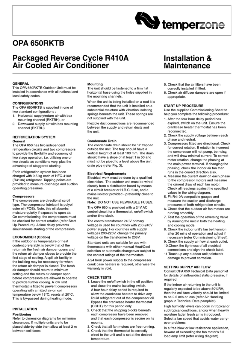
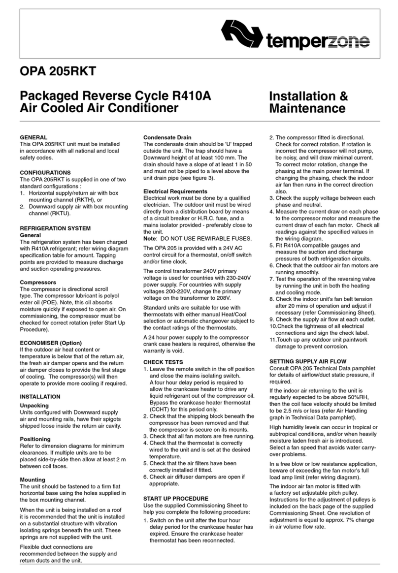
TemperZone ISD 380KBY Maintenance and service guide
Other TemperZone Air Conditioner manuals
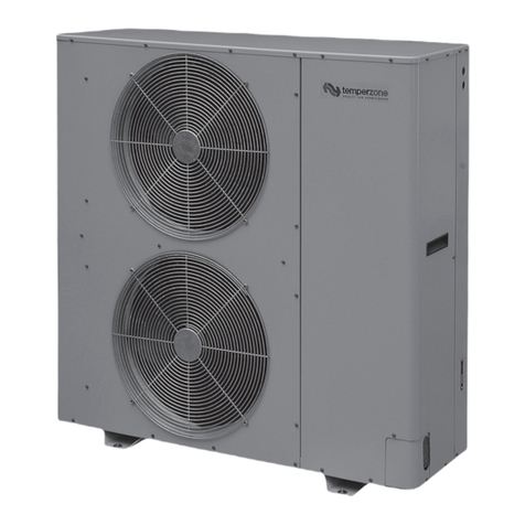
TemperZone
TemperZone OSA 175RKTHG Maintenance and service guide

TemperZone
TemperZone OPA RKTG-P Series Maintenance and service guide
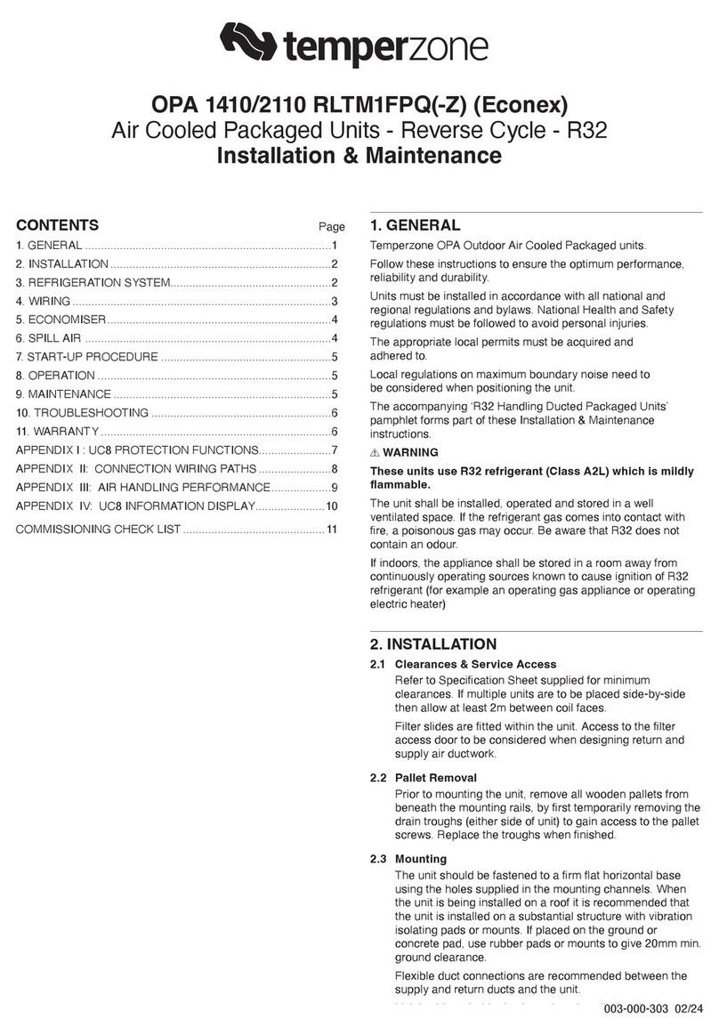
TemperZone
TemperZone OPA 1410 RLTM1FPQ Maintenance and service guide
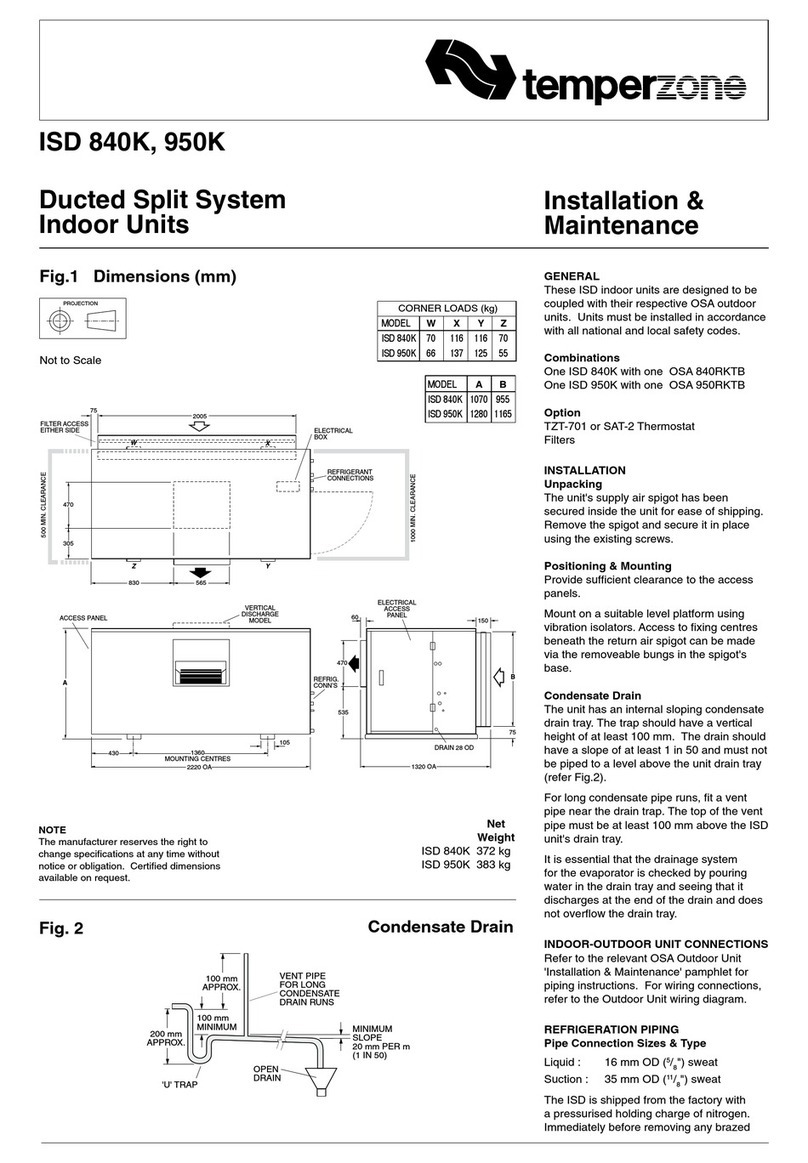
TemperZone
TemperZone ISD 840K Maintenance and service guide
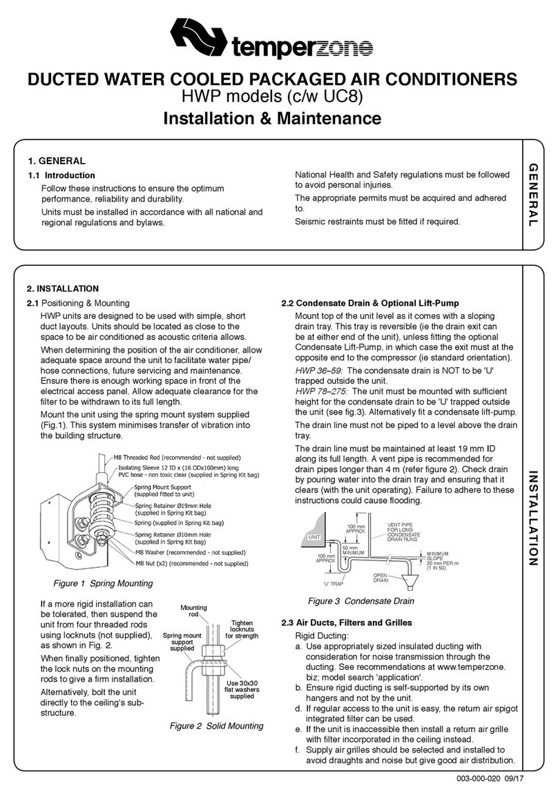
TemperZone
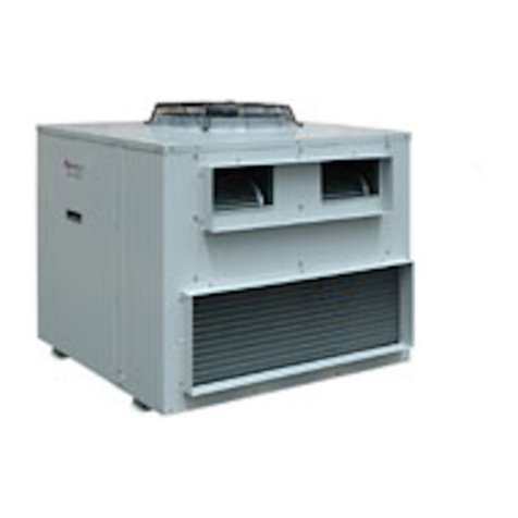
TemperZone HWP Series Maintenance and service guide
TemperZone
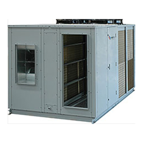
TemperZone OPA 201RKTY Maintenance and service guide
TemperZone
TemperZone OPA 1370RKTMG01-PZ Maintenance and service guide
TemperZone
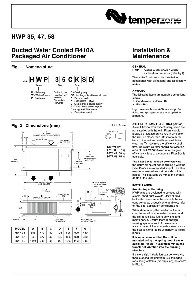
TemperZone HWP 35 Maintenance and service guide
TemperZone
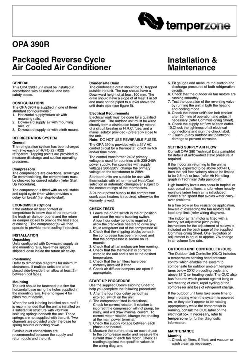
TemperZone OPA 390R Maintenance and service guide
TemperZone
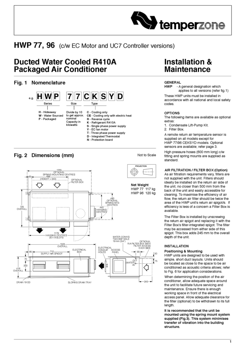
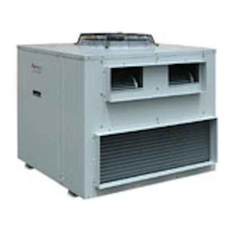
TemperZone HWP 96 Series Maintenance and service guide
TemperZone
TemperZone OPA 186RKTYG Maintenance and service guide
TemperZone
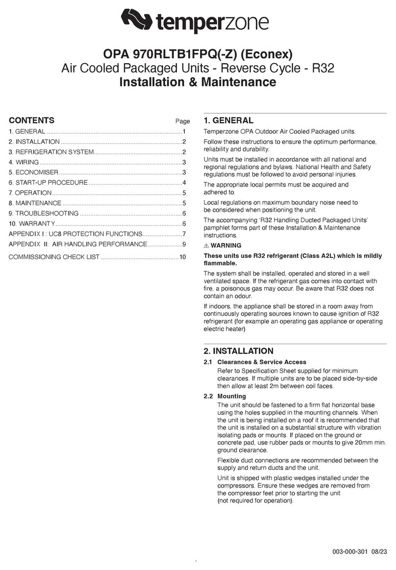
TemperZone OPA 970RLTB1FPQ Maintenance and service guide
TemperZone
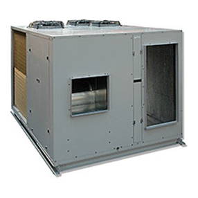
TemperZone OPA 550RKTB Maintenance and service guide
TemperZone
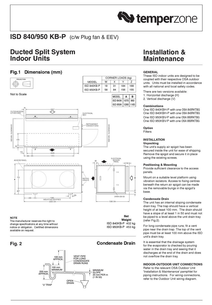
TemperZone ISD 840KB-P Maintenance and service guide
TemperZone
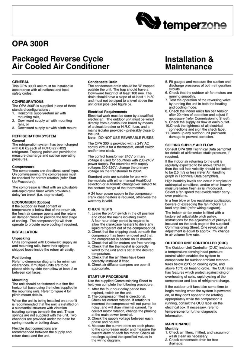
TemperZone OPA 300R Maintenance and service guide
TemperZone
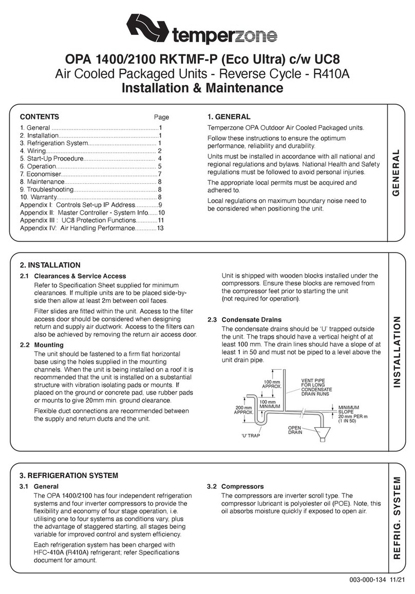
TemperZone EcoULTRA OPA 2100RKTM-P Maintenance and service guide
TemperZone
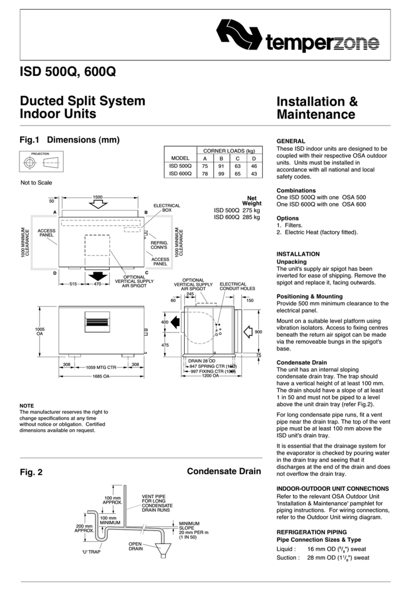
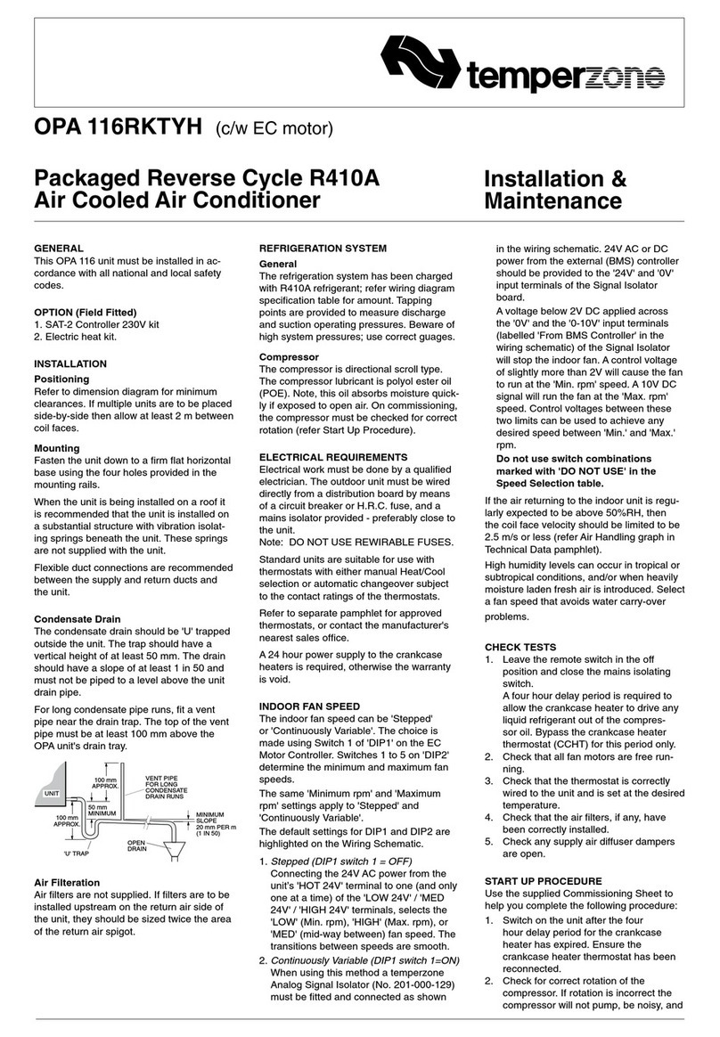
TemperZone ISD 500Q Maintenance and service guide
TemperZone
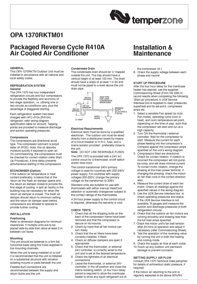
TemperZone OPA 116RKTYH Maintenance and service guide
TemperZone
TemperZone OPA 1370RKTM01 Maintenance and service guide

TemperZone
TemperZone OSA 160RKTGH Maintenance and service guide
Popular Air Conditioner manuals by other brands

CIAT
CIAT Magister 2 Series Installation, Operation, Commissioning, Maintenance

Bestron
Bestron AAC6000 instruction manual

Frigidaire
Frigidaire FFRE0533S1E0 Use & care guide

Samsung
Samsung AS09HM3N user manual

Frigidaire
Frigidaire CRA073PU11 use & care

Soleus Air
Soleus Air GB-PAC-08E4 operating instructions

McQuay
McQuay MCK020A Technical manual

Webasto
Webasto Frigo Top 25 DS Instructions for use

Frigidaire
Frigidaire FAZ12ES2A installation instructions

Mitsubishi Electric
Mitsubishi Electric MSC-GE20VB operating instructions

Mitsubishi Electric
Mitsubishi Electric PLA-M100EA installation manual

Daikin
Daikin Split Sensira R32 Service manual
