OPA 161RKTYH (c/w EC motor)
Packaged Reverse Cycle R410A
Air Cooled Air Conditioner Installation &
Maintenance
will stop the indoor fan. A control voltage
of slightly more than 2V will cause the fan
to run at the 'Min. rpm' speed. A 10V DC
signal will run the fan at the 'Max. rpm'
speed. Control voltages between these
two limits can be used to achieve any
desired speed between 'Min.' and 'Max.'
rpm.
Do not use switch combinations
marked with 'DO NOT USE' in the
Speed Selection table.
If the air returning to the indoor unit is
regularly expected to be above 50%RH,
then the coil face velocity should be limited
to be 2.5 m/s or less (refer Air Handling
graph in Technical Data pamphlet).
High humidity levels can occur in tropical or
subtropical conditions, and/or when heavily
moisture laden fresh air is introduced. Select
a fan speed that avoids water carry-over
problems.
CHECK TESTS
1. Leave the remote switch in the off
position and close the mains isolating
switch.
A four hour delay period is required to
allow the crankcase heater to drive any
liquid refrigerant out of the compres-
sor oil. Bypass the crankcase heater
thermostat (CCHT) for this period only.
2. Check that all fan motors are free
running.
3. Check that the thermostat is correctly
wired to the unit and is set at the desired
temperature.
4. Check that the air filters, if any, have
been correctly installed.
5. Check any supply air diffuser dampers
are open.
START UP PROCEDURE
Use the supplied Commissioning Sheet to
help you complete the following procedure:
1. Switch on the unit after the four
hour delay period for the crankcase
heater has expired. Ensure the
crankcase heater thermostat has been
reconnected.
2. Check for correct rotation of the
compressor. If rotation is incorrect the
compressor will not pump, be noisy, and
will draw minimal current. To correct
motor rotation, change the phasing at
the main power terminal.
3. Check the supply voltage.
4. Measure the current draw on the
compressor motor and on each fan
motor. Check all readings against the
specified values - particularly the indoor
fan amps if the unit is installed in a free
blow application.
Compressor
The compressor is directional scroll
type. The compressor lubricant is polyol
ester oil (POE). Note, this oil absorbs
moisture quickly if exposed to open air. On
commissioning, the compressor must be
checked for correct rotation (refer Start Up
Procedure).
ELECTRICAL REQUIREMENTS
Electrical work must be done by a qualified
electrician. The outdoor unit must be wired
directly from a distribution board by means
of a circuit breaker or H.R.C. fuse, and a
mains isolator provided - preferably close to
the unit.
Note: DO NOT USE REWIRABLE FUSES.
Standard units are suitable for use with
thermostats with either manual Heat/Cool
selection or automatic changeover subject
to the contact ratings of the thermostats.
Refer to separate pamphlet for approved
thermostats, or contact the manufacturer's
nearest sales office.
A 24 hour power supply to the crankcase
heaters is required, otherwise the warranty
is void.
INDOOR FAN SPEED
The indoor fan speed can be 'Stepped'
or 'Continuously Variable'. The choice is
made using Switch 1 of 'DIP1' on the EC
Motor Controller. Switches 1 to 5 on 'DIP2'
determine the minimum and maximum fan
speeds.
The same 'Minimum rpm' and 'Maximum
rpm' settings apply to 'Stepped' and
'Continuously Variable'.
The default settings for DIP1 and DIP2 are
highlighted on the Wiring Schematic.
1. Stepped (DIP1 switch 1 = OFF)
Connecting the 24V AC power from the
unit’s 'HOT 24V' terminal to one (and only
one at a time) of the 'LOW 24V' / 'MED
24V' / 'HIGH 24V' terminals, selects the
'LOW' (Min. rpm), 'HIGH' (Max. rpm), or
'MED' (mid-way between) fan speed. The
transitions between speeds are smooth.
2. Continuously Variable (DIP1 switch 1=ON)
When using this method a temperzone
Analog Signal Isolator (No. 201-000-129)
must be fitted and connected as shown
in the wiring schematic. 24V AC or DC
power from the external (BMS) controller
should be provided to the '24V' and '0V'
input terminals of the Signal Isolator
board.
A voltage below 2V DC applied across
the '0V' and the '0-10V' input terminals
(labelled 'From BMS Controller' in the
wiring schematic) of the Signal Isolator
GENERAL
This OPA 161 unit must be installed in
accordance with all national and local safety
codes.
OPTION (Field Fitted)
SAT-2 Controller 24V kit – for stepped fan
speed control.
INSTALLATION
Positioning
Refer to dimension diagram for minimum
clearances. If multiple units are to be placed
side-by-side then allow at least 2 m between
coil faces.
Mounting
Fasten the unit down to a firm flat horizontal
base using the four holes provided in the
mounting rails.
When the unit is being installed on a roof
it is recommended that the unit is installed
on a substantial structure with vibration
isolating springs beneath the unit. These
springs are not supplied with the unit.
Flexible duct connections are recommended
between the supply and return ducts and
the unit.
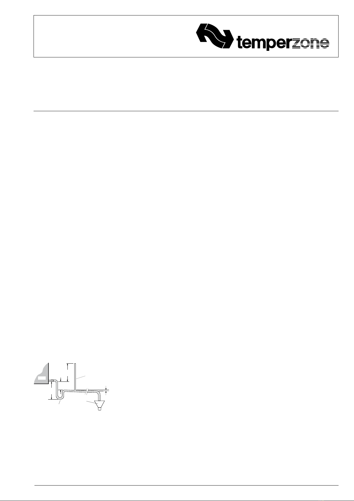
Condensate Drain
The condensate drain should be 'U' trapped
outside the unit. The trap should have a
vertical height of at least 50 mm. The drain
should have a slope of at least 1 in 50 and
must not be piped to a level above the unit
drain pipe.
For long condensate pipe runs, fit a vent
pipe near the drain trap. The top of the vent
pipe must be at least 100 mm above the
OPA unit's drain tray.
REFRIGERATION SYSTEM
General
The refrigeration system has been charged
with R410A refrigerant; refer wiring
specification table for amount. Tapping
points are provided to measure discharge
and suction operating pressures. Beware of
high system pressures; use correct guages.
OPEN
DRAIN
MINIMUM
SLOPE
20 mm PER m
(1 IN 50)
50 mm
MINIMUM
100 mm
APPROX.
'U' TRAP
100 mm
APPROX.
VENT PIPE
FOR LONG
CONDENSATE
DRAIN RUNS
UNIT


