2
Mount the unit level as it comes with a
sloping drain tray. This tray is reversible
– but not if using the optional condensate
lift-pump; then the drain exit can only be at
the opposite end to the compressor.
The drain line must have a slope of at least
1 in 50 and must not be piped to a level
above the drain tray. Where required a
condensate lift-pump should be used
(optional extra).
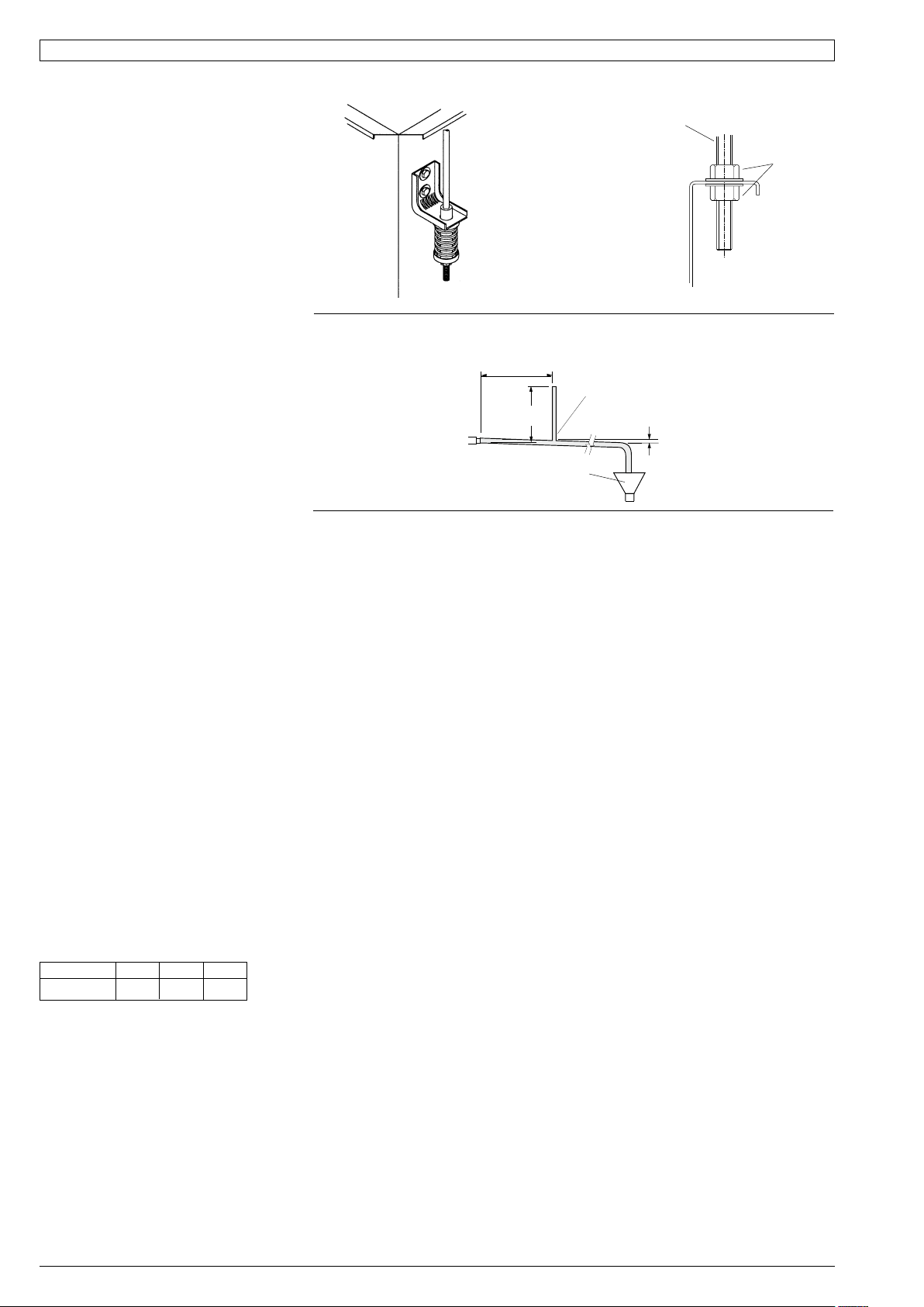
When finally positioned, tighten the lock
nuts on the mounting rods to give a firm
installation (see Fig. 4).
Condensate Drain
The condensate drain is not to be trapped
outside the unit. The drain line must be
maintained at least 19 mm ID along its
full length. Fit a vent pipe within 500 mm
of the unit, 300 mm high and 10 mm
ID (minimum); see Fig. 5. Check drain
by pouring water into the drain tray and
ensuring that it clears. Failure to adhere to
these instructions could cause flooding.
Water Supply & Return
The HWP unit's IN and OUT water
connections are male pipe threaded (refer
Fig. 1). The two temperzone 600 mm
flexible high pressure water hoses supplied
have female pipe threaded connections at
each end. Maximum water pressure for
each hose is 1720 kPa (250 psi). The HWP
unit alone, excluding hoses, will withstand
4480 kPa (650 psi).
Poor quality water supply must be pre-
filtered and it is essential that adequate
water treatment is maintained, particularly
where open cooling towers are used.
Note: It is required that the water supply
system be fitted with a water flow switch and
water pump safety interlock. These items
prevent the HWP units from going into fail
safe lockout status due to a loss of water
flow. Failure to install the above items would
require the resetting of all HWP units in the
system - either by breaking the power supply
to each unit or breaking the thermostat
control circuit.
HWPSR units require a minimum water
supply temperature of 17°C.
Circuit Balancing Valve
It is recommended that a circuit balancing
valve be fitted to maintain water flow at a
constant rate. The minimum water flow rates
in litres per second (l/s) are as follows:
HWP: 35 47 58
Minimium 0.17 0.27 0.36
Electrical
The air conditioner should be connected
to the appropriate power supply for each
model, as specified in the wiring diagram,
with neutral and adequate earth. The supply
to have an accessible switch to allow
isolation of the unit. Wire the heating and
cooling room thermostat to the electrical
terminals adhering to the wiring diagram
supplied with the unit. All wiring to the air
conditioner must comply with the wiring
regulations of the local electrical authority.
Air / Water Flow
Refer to HWP 35–58 Data Sheet pamphlets
for detailed information on air handling
performance and water flow rates.
Unit Protection
Unit protection is incorporated in either:
a.) HWP Protection Board, or
b.) SAT-2 Controller,
depending on which HWP model is being
installed.
A pump verification relay ensures that water
is flowing before the compressor will start.
A high pressure lockout protects the unit
from low water flow in cooling mode, or fan
failure in heating mode. Sensors protect
against low air coil temperature and loss of
refrigerant. Units include an anti rapid cycle
device for compressor protection.
HWPSR units also have a low refrigerant
temp. safety thermostat to protect against
icing up of the water within the unit's tube-in-
tube heat exchanger.
A non-specific fault LED/ output signal is
also included for remote fault indication to
building management systems (refer wiring).
Note: Lockout protection can be reset by
switching unit's power supply off and on.
Lockout protection will also reset when the
thermostat switches, or is switched to the
dead zone.
Units Supplied With SAT-2 Thermostat
Any faults detected are displayed on the
SAT-2 Wall plaque (refer Table 1). A non-
specific fault output signal is also included on
SAT-2 Controllers for remote fault indication
to building management systems.
Units Supplied With Electric Heat
HWPSCEKS models supplied with electric
heat include both auto (90°C) and manual
(120°C) high temp. safety thermostats. If the
manual safety t/stat requires resetting, then
the auto safety t/stat has failed and needs to
be replaced.
Room Thermostat
(Reverse Cycle Models)
The thermostat should be set within the
recommended operating range of between
19°C and 30°C. The thermostat should
not be used as an on-off switch. Refer to
temperzone for a list of other approved
thermostats.
If your unit is supplied with temperzone's
SAT-2 Thermostat, refer to page 3 for
installation instructions.
COMMISSIONING
1. Check that the thermostat is correctly
wired and set at the desired temperature.
2. Check that the air filter (if fitted) is clean.
3. Check that the fan runs freely without
vibration.
4. Check condensate drain and safety drain
tray for free drainage.
Demonstrate the SAT-2 Wall Control (if
supplied) to the owner/user, after having
first thoroughly familiarised yourself with the
User's Operating Instructions. This page is to
remain with the owner/user.
MAINTENANCE
Quarterly
1. Remove lint and dust accumulation from
heat exchange air coil. (Note: failure to
do this may affect efficiency).
2. Check air filters and vacuum or wash
clean as necessary.
3. Check condensate drain for free
drainage.
4. Check compressor compartment for oil
stains indicating refrigerant leaks.
5. Check quality of water supply.
Six Monthly
Check tightness of electrical connections.
Yearly
1. Remove lint and dust accumulation from
heat exchange air coil. (Note: failure to
do this may affect efficiency).
2. Replace air filter if damaged to maintain
adequate air flow and efficiency.
Fig. 3 Spring Mounting Fig. 4 Solid Mounting
MOUNTING
ROD TIGHTEN
LOCKNUTS
FOR
STRENGTH
PREFERRED
MOUNTING
SYSTEM
(SUPPLIED)
Fig. 5 Condensate Drain
OPEN
DRAIN
MINIMUM
SLOPE
20 mm PER m
(1 IN 50)
300 mm
APPROX.
VENT PIPE (10 ID)
FOR LONG
CONDENSATE
DRAIN RUNS
500 mm MAX.
FROM UNIT
NO TRAP
REQUIRED


