- 2 -
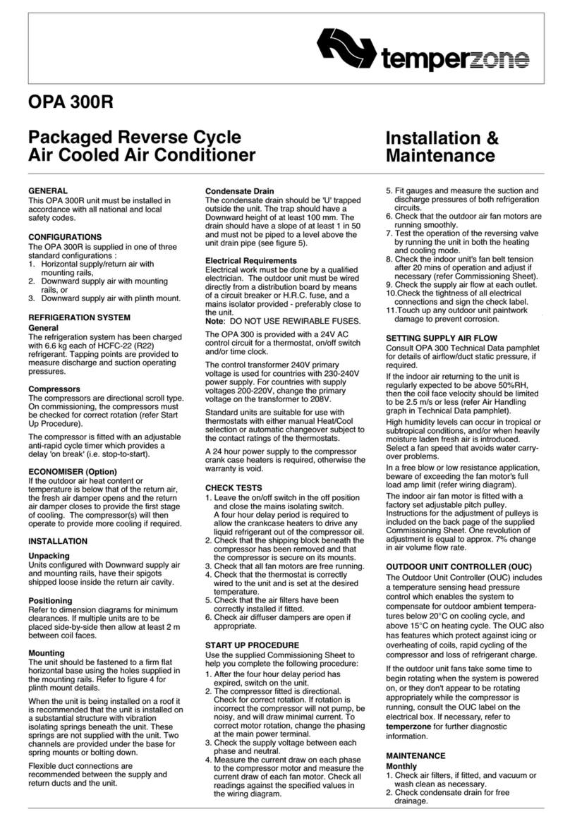
The unit is shipped with plastic wedges installed under the
compressors. Ensure these wedges are removed from the
compressor feet prior to starting the unit
(not required for operation).
2.4 Economiser/Fresh Air Inlet Option
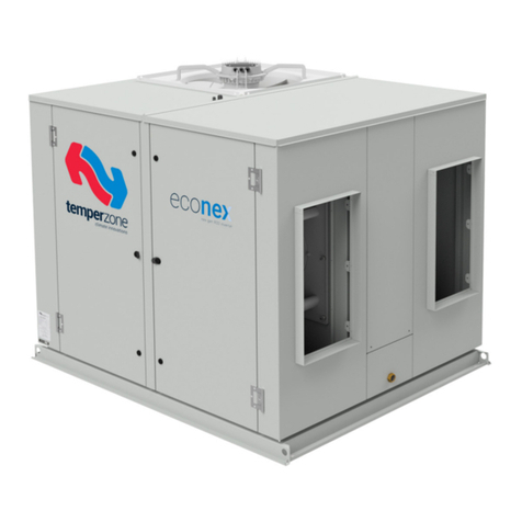
The Economiser/Fresh Air Inlet cowl is supplied separately
and must be tted to the unit – after the unit is lifted in to
place. Screws and pre-drilled holes are provided. Ensure
the top of the cowl is tucked under the roof lip of the air
conditioner and that all joints are sealed with silicon sealant.
There must be at least 300mm clearance beneath the cowl
once it is tted in place.
2.5 Spill Air Option
Spill Air cowl is supplied separately and must be tted to the
unit – after the unit is lifted in to place. The Spill Air cowl ts
below the Fresh Air cowl. Screws and pre-drilled holes are
provided. There must be at least 300mm clearance beneath
the cowl once it is tted in place.
2.6 Condensate Drains
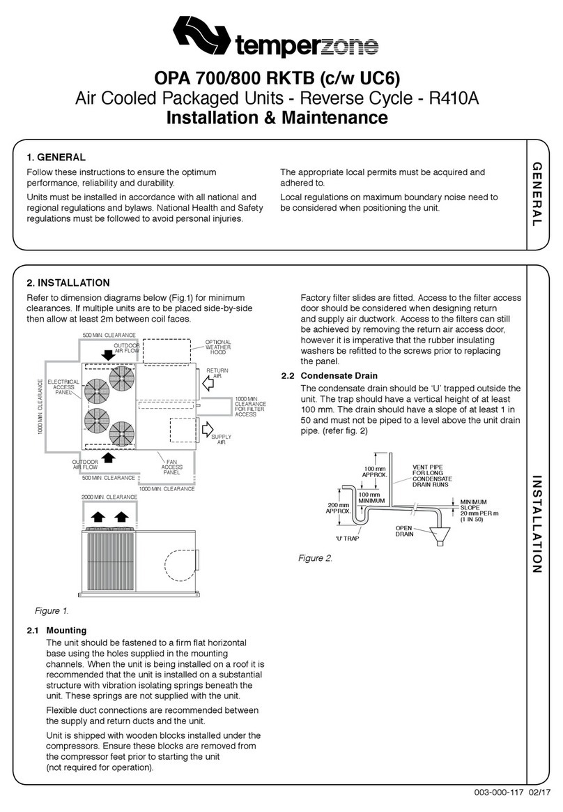
The condensate drains should be ‘U’ trapped outside the
unit. The traps should have a vertical height of at least 100
mm. The drain lines should have a slope of at least 1 in 50
and must not be piped to a level above the unit drain pipe.
OPEN
DRAIN
MINIMUM
SLOPE
20 mm PER m
(1 IN 50)
100 mm
MINIMUM
200 mm
APPROX.
'U' TRAP
100 mm
APPROX.
VENT PIPE
FOR LONG
CONDENSATE
DRAIN RUNS
3. REFRIGERATION SYSTEM
3.1 General
Each OPA 1410/2110 has four refrigeration systems – one
with a variable speed inverter compressor; the remaining
three are xed speed compressors.
Each refrigeration system has been charged with R32
refrigerant; refer Specications document for amount.
3.2 Compressors
The compressors are inverter and xed speed scroll
type. The compressor lubricant is POE-46 (NXG5020
or equivalent). Note, this oil absorbs moisture quickly if
exposed to open air.
4. WIRING
4.1 Electrical Requirements
Electrical work must be done by a qualied electrician
and
meet standard AS/NZS 3000.
!
DANGER! LIVE ELECTRICAL CONNECTIONS. ISOLATE MAINS
POWER BEFORE WORKING ON UNIT. ONLY QUALIFIED PERSONS
WHO ARE COMPETENTLY TRAINED SHOULD PERFORM SERVICE AND
MAINTENANCE TASKS.
The unit must be wired directly from a distribution board
using an appropriately sized circuit breaker. The termination
point for the mains cable is in the electrical compartment. An
isolating switch is required, near but not on the unit.
Refer Appendix III (p.8) for cable entry hole locations and
recommended wiring paths.
4.2 Control options
OPA Econex units can be controlled using any of the
following options:
• TZT-100 wall thermostat
• 24V AC and 0-10V signals from an external controller or
thermostat
• Remote on/off switch and/or time clock
• Modbus RTU serial communications over RS485
connection
• BACnet-IP serial communications over Ethernet
connection (with optional gateway module)
Standard reverse cycle units are suitable for use with
thermostats and controls with manual heating/cooling
selection or automatic change-over.
A unit wiring diagram is supplied alongside the electrical
board and in the Specications document.
4.3 TZT-100 wall thermostat
To connect the thermostat to the unit, use 4 core shielded
twisted pair type cable, suitable for RS485 communications.
(p/n 201-000-399). Signals A & B should form one twisted
pair.
Connect the thermostat as follows:
Drawn:
Apprvd:
Title: Drawing No: Rev:
Date:
©temperzone Ltd 2023 DO NOT
SCALE - ASK
Client Wiring
SHEET OF
For Client Wiring to Terminal Blocks & Descriptions, Refer Sheet 5
5
5
A
291-003-468
Wiring Schematic
OPA1410 / 1710 / 2110RLTM1FPQ-S1 R32 UC8
L.C 03-03-22
Sensor(S) / Transducers (T) to UC8
Name Type Colour
DL Discharge SGrey
SL Suction SWhite
AMB Ambient SBlack
DEI Deice SBlue
LPT Suction Pressure T Grey
HPT High Pressure TGrey
IFM
1
IFM
2
IFM
3
IFM
4
System 1
Compressor
System 4
Compressor
System 2
Compressor
System 3
Compressor
Indoor Coil Layout
OD Coil Sys 1 OD Coil Sys 2
OD Coil Sys 4 OD Coil Sys 3
OFM
2
CMM
1
Overall System Layout
OFM
3
CMM
2
CMM
3
CMM
4
OFM
1
OFM
4
TO / FROM CUSTOMER'S
SUPPLY / CONTROL
Client Wiring
Client External Protection and Isolator
Switch
Client Wiring
COMPRESSOR UC8 DIP SWITCHES
ON
SYS 1 INVERTER 1, 4, 6, 7, 10, 14
SYS 2 FIXED CAPACITY 1, 4, 6, 7, 10, 11, 14
SYS 3 FIXED CAPACITY 1, 4, 6, 7, 10, 12, 14
SYS 4 FIXED CAPACITY 1, 4, 6, 7, 10, 11, 12, 14
24VCB 24 Volt Circuit Breaker
CBL Cable Marker
CCB Control Circuit Breaker
CCH Crankcase Heater
CMC Compressor Contactor
CMCB Compressor Circuit Breaker
CMM Compressor Motor
CMOL Compressor Overload
CR Control Relay
DMF Damper Motor Fresh Air
DMR Damper Motor Return Air
DMS Damper Motor Spill Air
EEV Electronic Expansion Valve
EMIFB Electromagnetic Interference Filter Board
ETH Earth
FRB Fault Relay Board
HPT High Pressure Transducer
IBB Insulated Bus Bar
IFCB Indoor Fan Circuit Breaker
IFM Indoor Fan Motor
LPT Low Pressure Transducer
MTB Main Terminal Block
OFCB Outdoor Fan Circuit Breaker
OFM Outdoor Fan Motor
PCLP P CLIP
PLR Phase Loss Relay
RV Reversing Valve
SCB Socket Circuit Breaker
SPS Single Phase Socket
TB Terminal Block
TR Transformer
TJ3W Terminal Junction 3 Way
UC8 Unit Controller 8
VSD Variable Speed Drive
VSDCB Variable Speed Drive Circuit Breaker
VSD DIP switch settings
DIP switch On/Off
1,4 On
2,3 Off
MTB
L2
L3
MTB
L1
MTB
N
If Remote On/Off option
fitted remove this link
COMP 1
COMP 2
COMP 3
COMP 4
TB20 DMF
TB19 FLT
C
TB18 FLT
TB22 DMR
TB26 COMP
1
TB33
CAP IN
0-10
TB34
CAP IN
0V
TB27 COMP
2
TB28 COMP
3
TB29 COMP
4
Ferrites
Part Number Frequency Type Number of Turns
A 012-001-074 High 1
Modbus Devices Address
UC8 44, 45, 46, 47
VSD 10
TB35
FAN IN
0-10
TB36
FAN IN
0V
TB31 COM
TB37 ON
TB38 0V
ON
24 Hour power required (on
L1) for control circuit and
crankcase heaters
Important Notes:
Portable RCD shall be used
with single phase socket.
TB24 DMS
TB25 DMS
U
TB32 COM
TB30 HEAT
HEAT
0-10VDC
24VAC /
12VDC
Phase Loss Relay
·PWR (Green) Indicator
lits when power is being
supplied .
·RY (Yellow) Indicator lits
when relay is operating.
0VAC / DC
0VDC
0-10VDC
0-10VDC
0VDC
TB47B
TB47T A1.2
TB47M B1.2
To BMS
Client BMS Input
Connect cable screen
to 'EARTH' terminal
TZT-100
24 24C B A T T
TB47B
TB47T A1.2
TB47M B1.2
TB51T 12V
Connect cable screen
to 'EARTH' terminal
TZT-100 (Optional) Connection
TB39
LOW
IN
TB40
MED
IN
TB41
HIGH
IN
LOW
MED
HIGH
24VAC /
12VDC
A
B
CD
E
+
Start Time = E
A
B
CD
E
+
Initial Voltage = A
Stop Time = E
A
B
CD
E
+
Temperzone Soft Starter
Default Settings
Instructions To Convert To Master-Master Control
1) Turn off power to entire system.
2) Turn off the following dip switches for system 2, system 3 and
system 4 fixed speed UC8 control.
·UC8 System 2 - dip switch 11
·UC8 System 3 - dip switch 12
·UC8 System 4 - dip switch 11 and 12
3) Move the jumper between terminal blocks TB46T and TB47T to
between TB47T and TB48T (refer to sheet 3).
4) Move the jumper between terminal blocks TB46M and TB47M to
between TB47M and TB48M (refer to sheet 3).
5) Turn power back on.
6) Check UC8 System 2 address is set as 45, UC8 System 3 address
is set as 46 and UC8 System 4 address is set as 47. If the address
is wrong, it needs to be changed.
TB53 OFFC
TB52 OFF1
TB58 IFFC
TB57 IFF1
Voltage Free
Contact
Use £ 24V/1A, not 230V
TB21 DMF
U
TB23 DMR
U
Voltage Free
Contact
Use £ 24V/1A, not 230V
Voltage Free
Contact
Use £ 24V/1A, not 230V
REV MODIFICATION DATE ECN APVD
AInitial Release LC
0V UC8 Enable Link Common
12V RS485 12V Supply Output
24V 24VAC Internal Supply
24V COM 24VAC Internal Supply Common
ACT 230VAC Active Supply
Ax.x RS485 A (+) Communication Signal
Bx.x RS485 B (-) Communication Signal
CAP IN 0-10 Compressor Capacity 0-10VDC Analogue Speed Control
CAP IN 0V Compressor Capacity Analogue Speed Control Common
COM UC8 Control Input Signals Common
COMP Compressor ON / OFF Signal
DMF Damper Motor Fresh Air 0-10VDC Command
DMF U Damper Motor Fresh Air 0-10VDC Feedback
DMR Damper Motor Return Air 0-10VDC Command
DMR U Damper Motor Return Air 0-10VDC Feedback
DMS Damper Motor Spill Air 0-10VDC Command
DMS U Damper Motor Spill Air 0-10VDC Feedback
FAN IN 0-10 Indoor Fan 0-10VDC Analogue Speed Control
FAN IN 0V Indoor Fan Analogue Speed Control Common
FLT UC8 Fault Relay Output Normally Closed Contact
FLT C UC8 Fault Relay Output Common Contact
HEAT Cooling / Heating Mode Selection Signal
HIGH IN Indoor Fan Fixed High Speed Control Signal Input
ID FAN 0-10 Indoor Fan 0-10VDC Analogue Speed Control
ID FAN GND Indoor Fan Analogue Speed Control Ground
IFF Indoor Fan Fault Relay Contact Signal
IFFC Indoor Fan Fault Relay Common
LOW IN Indoor Fan Fixed Low Speed Control Signal Input
MED IN Indoor Fan Fixed Medium Speed Control Signal Input
N Neutral
OFF Outdoor Fan Fault Relay Contact Signal
OFFC Outdoor Fan Fault Relay Common
ON UC8 Enable Link Contact
Note: Capacity Staging. A TZT-100 must be congured for
single-stage operation, the default setting.
TZT-100 has its own DIP switches that must be set as
follows:
DIP switch 2 ON Equipment type = Heat Pump
DIP switch 3 OFF Equipment stages = One
DIP switch 4 ON Reverse cycle valve on = Heating
4.4 Communications format for TZT-100
Communications format must be set as per recommended
Modbus RTU:
• Baud rate (bd or br) 19200
• Data bits 8
• Parity Even
• Stop bits (Pa) 1
• TZT-100 address (Ad) 7
The procedure to check and adjust these settings is:
1. Press and hold the O/RIDE button until the display
shows the PIN
2. Use the UP & DOWN buttons to select PIN code 88:21,
then press O/RIDE in installer mode.
3. Use the O/RIDE and PROG buttons to cycle through the
various installer settings.
If necessary, refer TZT-100 User Manual for more detail.
4.5 Remote on/off
The UC8 has an input for a remote on/off function on
terminal ‘On’, signal return is terminal ‘0V’. When used, the
remote on/off terminals should connect to a voltage-free
relay contact. When not used, the remote on/off terminals
should be shorted (‘bridged’).
