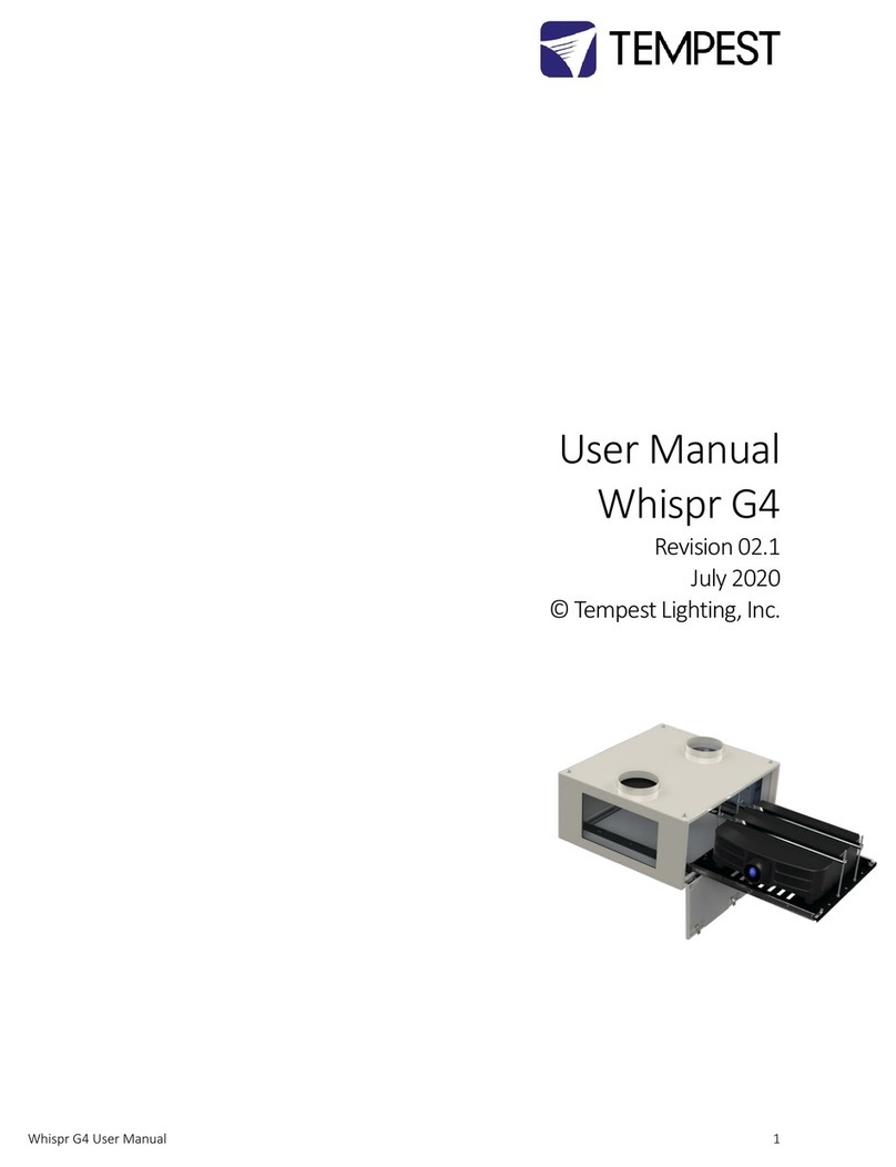
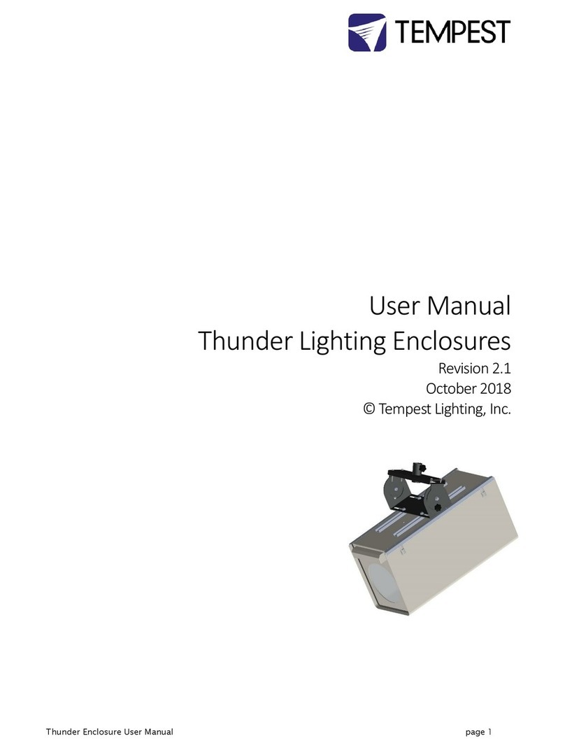
Tempest Cyclone 55.210L User manual

Cyclone User Manual 1
User Manual
Cyclone
Revision 8.8
September, 2021
© Tempest Lighting, Inc.

Cyclone User Manual 2
Table of Contents
Table of Contents........................................................................................................................................................................................ 2
Approvals –Europe ................................................................................................................................................................................ 6
Approvals –China................................................................................................................................................................................... 7
Introduction ................................................................................................................................................................................................ 8
IMPORTANT: Safety Advisories.............................................................................................................................................................. 8
Installation................................................................................................................................................................................................... 9
Dimensions, Weights & Rigging Points.................................................................................................................................................. 9
Access Clearance ..............................................................................................................................................................................10
Snow Clearance ................................................................................................................................................................................10
Mounting Hardware Options............................................................................................................................................................... 11
Mounting Bolts ................................................................................................................................................................................. 11
Mounting Options –Unistrut Kit .....................................................................................................................................................11
Mounting Options –Stacking Kit ..................................................................................................................................................... 12
Mounting Options –Swivel Stacking Kit.......................................................................................................................................... 12
Cyclovator 2 Tilt Kit...............................................................................................................................................................................13
SAFETY WARNING............................................................................................................................................................................. 13
Cyclovator –Unistrut Mounting Rails.............................................................................................................................................. 13
Cyclovator –Inlet Cowl .................................................................................................................................................................... 13
Fixing the Cyclovator in Place ..........................................................................................................................................................14
Mounting the Enclosure................................................................................................................................................................... 15
Setting the Show Position Stop........................................................................................................................................................ 16
Cyclone Angle Mount Kit...................................................................................................................................................................... 17
Angle Mount Kit Installation ............................................................................................................................................................ 17
ActiveCoolTM Cooling System............................................................................................................................................................... 19
Salt Fog Filter Kit Installation ........................................................................................................................................................... 20
Anti-Vibration kit Installation...........................................................................................................................................................21
Condensate Drain Hose.................................................................................................................................................................... 21
Important –Note these Warnings:.................................................................................................................................................. 22
ActiveCool Internal Filter .................................................................................................................................................................22
Mounting Hole Patterns................................................................................................................................................................... 23
Connecting the Air Hoses................................................................................................................................................................. 23
Power Connection............................................................................................................................................................................ 23
ActiveCool Temperature Gradient .................................................................................................................................................. 24
ActiveCool Control Settings ............................................................................................................................................................. 25
Set the ON/OFF Switch.....................................................................................................................................................................26
ActiveCool Troubleshooting Guide......................................................................................................................................................27

Cyclone User Manual 3
Basic Troubleshooting......................................................................................................................................................................27
Advanced Troubleshooting..............................................................................................................................................................27
ActiveCool dimensions..................................................................................................................................................................... 29
Using AC Assist with Cyclone Enclosures.................................................................................................................................................30
Estimating Heat Loads..........................................................................................................................................................................30
Connecting to the Enclosure(s)............................................................................................................................................................30
Connecting Air Hoses ...........................................................................................................................................................................31
Manifolds and Dampers.......................................................................................................................................................................32
AC Assist Dimensions............................................................................................................................................................................33
Wiring the Enclosure ................................................................................................................................................................................ 34
Power Wiring ........................................................................................................................................................................................ 34
SAFETY NOTICE................................................................................................................................................................................. 34
Electrical Standards..........................................................................................................................................................................34
AC Supply Voltage.............................................................................................................................................................................34
Wiring Access....................................................................................................................................................................................35
One or Two Power Circuits? ............................................................................................................................................................36
Single Feed Power Termination....................................................................................................................................................... 37
Split Feed Power Termination .........................................................................................................................................................37
North America 208V, Japan 200V Single Feed................................................................................................................................38
North America 208V, Japan 200V Split Feed ..................................................................................................................................38
International, 230V Single Feed.......................................................................................................................................................39
International, 230V Split Feed .........................................................................................................................................................39
Remote Monitoring Connections ........................................................................................................................................................40
DEC4 Ethernet Adapters –51.D4.15, 51.D4.23 ..............................................................................................................................41
51.D4.15 Default Configuration....................................................................................................................................................... 41
51.D4.15 Additional Support ...........................................................................................................................................................41
RS485 (DMX/RDM) Cable Terminations.......................................................................................................................................... 42
Line Termination Switch Settings .................................................................................................................................................... 43
System Manager Installation ...........................................................................................................................................................44
Enclosure Management................................................................................................................................................................... 46
Enclosure Monitoring.......................................................................................................................................................................46
DMX Control ..................................................................................................................................................................................... 48
Firmware Uploads ............................................................................................................................................................................ 48
Remote Configuration...................................................................................................................................................................... 48
Tempest Equipment Management Protocol ..................................................................................................................................49
Positive Pressure Fan Control Option.................................................................................................................................................. 50
Digital Enclosure Control..........................................................................................................................................................................51
Schematic.............................................................................................................................................................................................. 51

Cyclone User Manual 4
DEC4 Main Functions ...........................................................................................................................................................................52
Firmware Revision............................................................................................................................................................................ 52
Factory Settings –Data Modes............................................................................................................................................................ 52
Hardware Indicators & Fuses...............................................................................................................................................................53
Operating Modes..................................................................................................................................................................................54
RDM Only Monitor (Factory Default) .............................................................................................................................................. 54
RDM+DMX Control...........................................................................................................................................................................54
RDM+DMX Service ........................................................................................................................................................................... 54
DEC4 Control Parameters .................................................................................................................................................................... 55
Control Interface ..............................................................................................................................................................................56
User Interface LCD Display............................................................................................................................................................... 57
Control Interface Operation ............................................................................................................................................................57
Control Menu........................................................................................................................................................................................ 58
Set Data Options............................................................................................................................................................................... 58
Set Temp Units .................................................................................................................................................................................59
Set Temp Ranges ..............................................................................................................................................................................59
Set Max Humidity .............................................................................................................................................................................59
Set Lamp On Point............................................................................................................................................................................59
Reset Lamp Hours.............................................................................................................................................................................59
Set Fan Function...............................................................................................................................................................................60
Status Display.................................................................................................................................................................................... 60
Safe Mode.............................................................................................................................................................................................61
Safe Mode –What to do:................................................................................................................................................................. 61
DEC4 Firmware Updates .......................................................................................................................................................................... 63
Direct Firmware Update (System Control Board only).......................................................................................................................63
Indirect Firmware Updates ..................................................................................................................................................................67
Requirements ................................................................................................................................................................................... 67
Installation Procedure......................................................................................................................................................................67
Mounting the Projector............................................................................................................................................................................72
Projector Mounting - Landscape .....................................................................................................................................................72
Projector Mounting –Landscape, Feet-up .....................................................................................................................................73
Projector Mounting –Portrait/8 rigging points.............................................................................................................................. 73
Projector Mounting –Portrait/4 rigging points.............................................................................................................................. 75
Projector-specific Mounting ................................................................................................................................................................ 76
Christie D4K-40 RGB - Landscape .................................................................................................................................................... 76
Christie D4K-40 RGB –Portrait ........................................................................................................................................................ 77
DPI Insight 4K....................................................................................................................................................................................78
UST Projector Mounts.......................................................................................................................................................................... 78

Cyclone User Manual 5
Important: Check Lamp-on Current ....................................................................................................................................................79
Connect Projector and Aux Equipment...........................................................................................................................................79
Projector Connector Types ..............................................................................................................................................................80
Routine Maintenance............................................................................................................................................................................... 81
Clean Port Glass................................................................................................................................................................................ 81
Check Filter ....................................................................................................................................................................................... 81
Check Temperature/Humidity Sensor.............................................................................................................................................82
For After Sales Support ....................................................................................................................................................................82
Troubleshooting........................................................................................................................................................................................ 83
Warranty ...................................................................................................................................................................................................84
Appendix –TEMP Protocol.......................................................................................................................................................................85
Physical Layer........................................................................................................................................................................................ 85
Developer’s Guide ................................................................................................................................................................................ 85

Cyclone User Manual 6
Approvals –Europe
CERTIFICATE AND DECLARATION OF CONFORMITY
FOR CE MARKING
Tempest Lighting, Inc.
11845 Wicks Street, Sun Valley, CA 91352, USA
t: +1 818 787 8984 f: +1 818 252 7101 e: info@tempest.biz
www.tempest.biz
Tempest Lighting, Inc. declares that their
Cyclone Projector Enclosure Series 55.xxx.xx
complies with the Essential Requirements of the following EU Directives:
Low Voltage Directive 2014/35/EU Test Report 60065-6500-01-14
Electromagnetic Compatibility Directive 2014/30/EU Test Report 61000-6500-03-14
and further conforms with the following EU Harmonized Standards:
EN 60065 : 2014/AC:2016 Test Report 60065-6500-01-16
EN 60529:1991/AC:2016-12 Test Report 60529-6500-02-16
EN 61000-6-3:2007+A1:2011 Test Report 61000-6500-03-14
EN61000-6-1:2007 Test Report 61000-6500-03-14
EN55015:2019/A11:2020 Test Report 61000-6500-03-14
Dated: 21st September 2020
Position of signatory: President
Name of Signatory: Tim Burnham
Signed below:
on behalf of Tempest Lighting, Inc.
. . . . . . . . . . . . . . . . . . . . . . . . . . . . .

Cyclone User Manual 7
Approvals –China

Cyclone User Manual 8
Introduction
Thank you for purchasing a Tempest enclosure! We have worked hard to provide you with the very
best product available for its purpose, and we shall continue to do everything possible to ensure
that it works well for you for many years to come.
Please read this manual before starting work!
In the event of difficulty, please contact your Tempest reseller or Tempest direct:
+1 818 787 8984
We will do everything we can to help you get the very best results from your Tempest enclosure.
IMPORTANT: Safety Advisories
•All installation and rigging work done must where applicable be designed and built in
accordance with norms and standards of the local authority having jurisdiction of the
installation site. It is the responsibility of the installer to obtain such approvals as may be
required to achieve full compliance.
•All electrical work must be carried out by a suitably licensed electrical contractor in full
compliance with local electrical standards.
•Lifting: some enclosures and the equipment inside them may be heavy. Use properly
rated lifting equipment where appropriate and never attempt to carry out work with
fewer than the number of workers needed to lift safely.
•It is the responsibility of the installer to ensure that all local building, safety and electrical
codes are strictly adhered to in the installation of this enclosure. Tempest Lighting, Inc.,
its employees and agents are in no way responsible for damage arising from failure to
follow either the instructions in this manual or building, safety and electrical codes
prevailing at the installation location.
•Do not attempt to install or operate the enclosure before fully reading and understanding
this manual
•Never allow anyone who has not read this manual to open the enclosure or perform
maintenance on the projector within.
•Never leave the enclosure unattended when open.
•Always make sure all bolts and latches are tight and safety locks are in place after
performing any form of maintenance on the unit.
•Do not open any electrical boxes until power has been shut off to all supply lines to the
enclosure (including the one powering the projector).
•Do not open the enclosure in wet weather.

Cyclone User Manual 9
Installation
Dimensions, Weights & Rigging Points
We are adding models all the time –check our web site for submittal drawings or consult factory for models not shown here
Cyclone
A in
A mm
B in
B mm
C in
Cmm
D in
D mm
E in
E mm
W lb
W kg
55.210L
51
1,295
32
813
22
559
49
1,245
30
762
177
80
55.210P
51
1,295
25
635
34
864
49
1,245
23
584
213
97
55.240L
53
1,346
34
864
26
660
51
1,295
32
813
230
105
55.240P
53
1,346
25
635
34
864
51
1,295
23
584
222
101
55.250L
51
1,295
37
940
24
610
49
1,245
35
889
223
101
55.250P
51
1,295
25
635
41
1,041
49
1,245
23
584
257
117
55.305L
51
1,295
34
864
24
610
49
1,245
32
813
205
93
55.305P
51
1,295
25
635
36
914
49
1,245
23
584
226
103
55.310L
59
1,499
34
864
25
635
57
1,448
32
813
247
112
55.310P
59
1,499
25
635
36
914
57
1,448
23
584
261
119
55.314L
58
1,473
37
940
27
686
56
1,422
35
889
285
130
55.314P
58
1,473
25
635
40
1,016
56
1,422
23
584
271
123
55.320L
67
1,702
37
940
25
635
65
1,651
35
889
305
139
55.320P
67
1,702
25
635
38
965
65
1,651
23
584
313
142
55.324LAC
58
1,473
37
940
34
864
56
1,422
35
889
359
163
55.324PAC
58
1,473
30
762
41
1,041
56
1,422
28
711
351
160
55.525L
67
1,702
37
940
29
737
65
1,651
35
889
354
161
55.525P
67
1,702
30
762
40
1,016
65
1,651
28
711
376
171
55.525LAC
67
1,702
37
940
33
838
65
1,651
35
889
402
183
55.525PAC
67
1,702
30
762
44
1,118
65
1,651
28
711
415
189
Rigging Points:
M12-1.75 (bolts
supplied), 6 points top, 4
points bottom surface
For more detail, download 2-D PDF or DWG
and 3-D STEP files at
https://www.tempest.biz/product/cyclone/
B

Cyclone User Manual 10
Access Clearance
Observe these minimum access clearances shown around
your enclosure.
Enclosures may be placed side-by-side, with the projector
slides opposite, but we recommend allowing clearance for
service access on both sides wherever possible.
Snow Clearance
In areas where snow is likely, make sure the base of the
enclosure is at least 24” [60cm] above highest potential
snow drift level.
60cm/24in

Cyclone User Manual 11
Mounting Hardware Options
Mounting Bolts
•Each Enclosure must be mounted with at least FOUR
points (six points if hanging)
•All mountings must be made using the M12
threaded holes on the top or bottom of the
enclosure.
•Be sure to use the sealing washers supplied for any
top fixings.
•Use an 8mm hex key to secure the M12 socket cap
screws provided.
•Tempest recommends the use of stainless steel
mounting hardware.
•Make sure the inlet filter has at least 75mm/3in
clearance below.
IMPORTANT SAFETY NOTICE
Installer must ensure that all mounting points are secure
and conform to local safety regulations. Tempest Lighting
Inc. accepts no responsibility for damage or injury arising
from inappropriate or unsafe installation.
Mounting Options –Unistrut Kit
If mounting positions for the corner bolts are not
convenient, use the Unistrut Kit (55.UR.xxx) to add two
Unistrut rails to the top or bottom of the enclosure.
Using industry-standard Unistrut hardware, the enclosure
may now be attached at any point along the Unistrut
rails.
Note: Unistrut rails are required for use with the
Cyclovator mount –see below…
8mm
Mounted from Above:
M12-1.75 bolts
Use 8mm hex key
Sealing washers
Mounted from Below:
M12-1.75 bolts
Use 8mm hex key
Unistrut Rails may be
mounted above or
below

Cyclone User Manual 12
Mounting Options –Stacking Kit
Cyclone G4 may be stacked up to three units high, using
the 51.SK stacking Kit. You will need the total number of
Cyclones to be stacked, minus one stacking kit(s).
So, for a stack of three enclosures, order 3-1=2 stacking
kits.
Note: Cyclone enclosures must be of the same model to
stack in this way.
51.SK Stacking Kit (set of four, for one enclosure)
Mounting Options –Swivel Stacking Kit
Cyclone G4 may be stacked two units high, with beams up
to 40°apart, using the Swivel Stacking Kit. Enclosures
must be the same model.
This is very useful for edge-blending across a wide area
with a limited number of rigging positions.
51.SS.xxx (where xxx is the Cyclone model number) Swivel
stacking kit for two G4 Cyclone enclosures
Bolt top leg to M12
socket each corner
Bolt bottom leg to M12
socket each corner
Join top and bottom
sections together with
Clevis pins
Mount Swivel Brackets to
M12 threaded inserts in
enclosure frames with
the M12 bolts provided.
All four brackets are
identical
Join the radiused slots
using the Hex bolts and
nuts provided.
Adjust desired angle
and tighten nuts

Cyclone User Manual 13
Cyclovator 2 Tilt Kit
SAFETY WARNING
IT IS A SAFETY REQUIREMENT that Cyclone enclosures
with front or rear slide be horizontal any time you slide
the projector out for service. IT IS DANGEROUS to do this
if the enclosure is not horizontal, and MAY CAUSE
DAMAGE TO THE PROJECTOR OR INFLICT SERIOUS INJURY
TO PERSONNEL. Tempest Lighting Inc., its agents and
employees, will not be liable for consequences of failure
to heed this safety warning.
Cyclovator 2 may be used for any G3 or G4 Cyclone
enclosure.
The enclosure may be installed at ground level, projecting
up (up onto a building, for example)…
…or, on a rooftop, projecting downwards.
In either case, the maximum tilt angle is 60°.
Cyclovator –Unistrut Mounting Rails
When Cyclone G4 is used with the Cyclovator Tilt Kit, the
Unistrut Kit (55.UR.xxx) is required to attach the
enclosure to the Cyclovator.
‘xxx’ is the Cyclone model number.
Cyclovator –Inlet Cowl
When Cyclone G4 is used with the Cyclovator Tilt Kit, with
a tilt angle greater than 40°, use the inlet cowl 55.IC.xx to
protect the inlet filter from weather.
‘xx’ is the filter size in inches –15 for 55.200-350, 22 for
55.400 and up.
Stainless Steel Unistrut
Rail Kit 55.UR.xxx
Inlet Cowl 55.IC.xx

Cyclone User Manual 14
Fixing the Cyclovator in Place
The Cyclovator MUST be firmly attached to the ground, or
a suitable mounting structure, using four stainless steel
M12 (or US ½” size) bolts or anchors (not supplied).
Suitable substrates include concrete pads, steel
frameworks, roof beams. All mountings must comply with
all relevant building and safety norms in the jurisdiction
of the final installation. It is the responsibility of the
installer to obtain approval from a structural engineer or
other competent person for all such installations, and to
adhere strictly to local building and safety codes at all
times.

Cyclone User Manual 15
Mounting the Enclosure
Make sure that the Unistrut rails are attached securely to
the 4 (or 6) M12 threaded sockets on the bottom of the
enclosure frame.
Set the Cyclovator to its horizontal position:
1. Loosen the two locking knobs (a)
2. Turn the crank handle (b) until the Cyclovator
saddle is horizontal
3. Tighten the two locking knobs (a)
Align the channel spring nuts (c):
4. The distance (E) between the channel nuts
should be the same as dimension E in the
installation page (the distance between centers
of the Unistrut channels)
5. Loosen the channel nut
bolts and align the
channel nuts with their
long sides parallel with
the end of the
Cyclovator saddle:
6. Carefully set the Cyclone enclosure on the
Cyclovator saddle, so that the channel nuts are
INSIDE the Unistrut rails.
7. PUSH UP and tighten the four M12 channel nut
bolts, so that the channel nuts lock in the
Unistrut channels.
8. Loosen the locking knobs and turn the crank
handle to test movement.
Unistrut Rails
(a)
(b)
(a)
(c)
(E)
Cyclovator Saddle
Cyclovator Base

Cyclone User Manual 16
Steep Angles:
FIRST, MAKE SURE THE CYCLOVATOR IS SECURELY FIXED
TO THE GROUND.
For steep projection angles, loosen the four channel nut
bolts and carefully slide the enclosure in the direction
that will be ‘UP’.
The center of gravity will still be roughly centered in show
position, but you will have to work a bit harder to crank
the enclosure up to its show trim!
It is important to use the Inlet Cowl accessory for angles
above 30°.
Setting the Show Position Stop
Cyclovator gives you a locator for your show position, for
accurate show positioning.
With the Cyclovator in Show position:
1. Loosen the Locking Collar set screw (a)
2. Slide the Locking Collar firmly against the Acme
Nut Plate (b)
3. Tighten the Locking Collar set screw (a)
4. You now have two reference locations:
•Horizontal
•Show
ALWAYS MAKE SURE THAT BOTH LOCKING KNOBS (c) ARE
LOOSE WHEN RAISING/LOWERING THE CYCLOVATOR,
AND TIGHT WHEN IN SHOW OR SERVICE POSITION.
(a)
(b)
(c)

Cyclone User Manual 17
Cyclone Angle Mount Kit
The Angle Mount kit is a simple fixed mounting solution for up to two Cyclone enclosures with a tilt angle from 10-45°. Unlike
Cyclovator, once set, the tilt angle is fixed.
The Angle Mount kit may be used on the ground, with projection up to a building, or on a tall structure or flat roof, projecting
down.
Shooting up…. Shooting down…
Angle Mount kits are available in three sizes:
55.AM2 for Cyclone 210 –305
55,AM3 for Cyclone 310, 314, 324
55.AM4 for Cyclone 320, 525
Check with Tempest for Cyclone models not shown here or custom versions.
In certain cases, it will be safe to stack two Cyclone enclosures on one Angle Mount kit. Please note:
•Do not double-stack in exposed locations subject to high winds
•Do not double stack portrait enclosures
•Do not double stack if the tilt angle >30°
Angle Mount Kit Installation
Mark out the mounting pattern on the ground or substrate.
It is the same as the rigging points for the enclosure (see
Installation/Dimensions D and E above).
Use stainless steel hardware suited to the mounting
substrate, and in compliance with local construction codes to
mount the Unistrut rails securely to the substrate.
Use M12 or ½” hardware, 2 sets per Unistrut rail.
E
D
Mounting points (x 4)

Cyclone User Manual 18
Assemble the vertical strut assemblies between the hinged
Unistrut rails, set both to the same desired angle, and tighten
securely.
Mount the Cyclone enclosure on the two upper Unistrut rails,
and secure in place using the four M12 socket cap screws
provided:
Use one stacking kit (51.SK) to double stack a second
enclosure, observing the guidelines outlined above:
Unistrut Channel Nut
M12 Hex Bolt
Strut Assembly
M12 Washers
Unistrut Channel Nut
Hinge
Please Note:
For tilt angles > 30°, use 51.IC inlet cowl to
protect the inlet filter from wind-blown rain.
In most cases stacking will not be possible for
systems using ActiveCool or AC assist cooling.
Consult Tempest for details.

Cyclone User Manual 19
ActiveCoolTM Cooling System
Tempest ActiveCool is a closed-loop cooling solution
designed to keep sensitive laser projectors at a
constant temperature in any outdoor environment.
ActiveCool comprises the following main components:
1. Cooler Unit
2. Flow hose (150mm/6in padded hose)
3. Return hose (250mm/10in padded hose)
4. Power cable (connects to PowerCon True
TOP outlet on enclosure chassis)
5. Power relay added to enclosure controller
6. Internal recirculation fan
ActiveCool operation is automatic. Simply connect to
the cyclone enclosure, and set the desired
temperature, and the cooler will run automatically
when:
a) The DEC controller senses that the projector
has come out of standby mode
b) The projector is off but the upper
temperature setting has been reached
(normally during daytime in hot sun).
The cooler will maintain an air temperature inside the
enclosure within a few degrees of the target
temperature set in the ActiveCool controller.
Internal and External Airflows
The internal airflow (shown above) is isolated from
outside air, so filtering is not required. The internal air
is also de-humidified by the cooler action.
The external (compressor) airflow is subject to local
atmospheric conditions; in locations subject to salt air
(beaches or ships), chlorine (pool areas) or pollution
(city centers), the Salt Fog filter kit should be used.
This protects the compressor and other cooler
components from airborne contaminants.
The Salt Fog Kit also comes with a large cowl, to
protect the filter from rain and wind-blown dust and
sand –strongly recommended in desert conditions. A
door, operated by air pressure, protects the
compressor exhaust from contamination when the
cooler is not running.
Enclosure airflow is
isolated from exterior
air and compressor
airflow
Note: Enclosure hose connection points may vary.
INTERNAL AIRFLOW
Salt Fog Kit
Exhaust
Flap
Salt Fog Kit
Filter Cowl

Cyclone User Manual 20
Salt Fog Filter Kit Installation
1. Remove the screws around the condenser
inlet and exhaust grilles.
2. Fit the salt fog filter (gold side out) inside the
louver box.
3. Attach the filter/louver assembly to the
cooler, using the screws removed in step 1.
4. Mount the exhaust door frame onto the
condenser exhaust grille with the four
screws provided.
5. Assemble the door, washers and stainless
steel bearing, and fix to the door frame with
the two screws provided. MAKE SURE THE
WASHERS ARE BETWEEN THE DOOR AND
THE INSIDE OF THE DOOR FRAME.
Filter Cowl Screws
Filter Cowl
Filter (gold side out)
Door
Washers
Bearing
Bracket
Door Frame
This manual suits for next models
42
Table of contents
Other Tempest Enclosure manuals
Popular Enclosure manuals by other brands

Fractal
Fractal FD-C-POA1A-01 user guide
Altronix
Altronix Trove T1RAL13F8P8 installation manual

EcoxGear
EcoxGear ECOEXTREME quick guide
Technologic Systems
Technologic Systems TS-ENC530 user manual

Teledyne Lecroy
Teledyne Lecroy WavePro HD Assembly instructions
Panduit
Panduit PANZONE PZWIFIENA instructions
QNAP
QNAP TL-R1200S-RP Quick installation guide
Phanteks
Phanteks Enthoo Evolv ATX user manual

Audiovox
Audiovox BP10 owner's manual
Thermaltake
Thermaltake Element T VK9000 Series user manual

ABB
ABB System pro E power PUPM1800 Instruction handbook
Martin Audio
Martin Audio Touring and Theatre WTUB Specifications
